Abstract
Nowadays, destructive bomb effects and terroristic attacks to buildings have become a challenge for structure engineers. Reinforcement of structures with composite materials has been extensively increased in recent decays, because of their individual and unique characteristics like high impact strength, flexibility, high-weight ratios, etc. The technique of wrapping concrete with CFRP/GFRP sheets can significantly increase its axial load capacity, flexibility and seismic behavior of columns in the plastic hinge areas or overlapping regions of column bars. In this research, blast phenomena and its effects on buildings will be analytically investigated. CFRP/GFRP sheets will be applied to the retrofitted building frames and their performance in strengthening structural members will be studied. The concrete nonlinearity behavior is considered in using concrete damage plasticity model and CFRP/GFRP sheet has been assumed to be elastic and isotropic, while steel retrofitting bars have elasto-plastic behavior. For validation of analytical results, a model has been compared with a series of experimental results, and good agreements have been obtained. Results show that external reinforcement increases energy absorption of the system up to three times, and in this case, reinforcement by CFRP sheets represents better performance. In addition, it is shows that external reinforcement of connections leads to decrease total displacement of the frame up to 40 %. Moreover, effects of the number of reinforcement layers are considered.
1. Introduction
The main target of structural design is to protect occupants, contents and essential performance of buildings. One essential performance can be the ability of serviceability after heavy damages due to a big explosion. Due to the complex behavior of structures, especially concrete structures under severe dynamic loads, a lot of laboratory, numerical and analytical models have been presented by many researchers. Since 1990s, extensive research has been conducted to retrofit existing concrete and other (masonry, metal and timber) structures using externally bonded FRP composites [1]. This kind of retrofitting is easy to use, having minimal disruption to the structure. The method is also cost-effective compared with other methods [2, 3]. So, FRP materials are applied to reinforce the deck beams and concrete bridge columns. FRPs have been used in many other structural elements and are widely used in developed countries as a new building material, because of its useful results. In 2004, Parretti and Nanni tested the effect of carbon fiber orientation. Results indicated that the ultimate capacity of ±45-degree FRP laminate strengthened rectangular columns is a little lower than the columns reinforced with fibers in the hoop direction [4]. In 2007, a test was conducted on a column externally wrapped with two types of materials, GFRP and CFRP, subjected to the eccentric load. Results show that considerable gains in strength and ductility were obtained when the columns were confined with CFRP (vertical straps and horizontally wrapped) [5]. Jankowiak and Ladygowski, by performing a laboratory test, presented a method and requirements of the material parameter identification for concrete damage plasticity constitutive model [6]. In 2008, an experimental research was done to investigate the behavior of square concrete column confined with GFRP composite warp, and it was shown that composite wrapping could enhance the structural performance of concrete columns under axial loading [7]. In another laboratory test, twenty- five experimental reinforced concrete columns confined with CFRP composites subjected to axial monotonic compression were investigated by Chastre and Silva in 2010.Simulation of behavior of circular reinforced concrete columns was conducted by a numerical model [8]. Buchan and Chen performed an experimental and finite element (FE) model in retrofitting concrete and masonry structures with fiber reinforced polymer (FRP) composites for blast protection [2].
Extensive research into blast loads and their effect has been done and different methods have been presented to protect structures against these extraordinary loads. In this paper, a numerical research has been done to survey how much retrofitting with CFRP/GFRP sheets and longitudinal bars will be effective when subjected to explosive load. A two-span two-story concrete frame reinforced with CFRP/GFRP sheets is investigated under explosive loads. Finite element software, ABAQUS [9], which has a high capability in representation (showing) exact material behavior, FRP modeling, blast loads, considering the material and geometric nonlinearity, has been used.
2. Finite element models
As mentioned before, a concrete frame which has two spans and two stories is modeled by ABAQUS [9] software. Concrete elements of the frame are reinforced by steel longitudinal bars and stirrups. As a parameter, some parts of the frame such as columns and connections are strengthened with external CFRP and GFRP strips. Also, in order to comprehensively compare; three other models are considered. Two models in which whole of the frame is confined by CFRP and GFRP sheets, and a model without any external reinforcing sheets.
To evaluate validation of finite element modeling, a circular column is modeled similar to the laboratory sample having been done by Chastre and Silva [8], named “Valid-model”.
The geometric characteristics of the models and material properties are considered according to the laboratory test having been done by Chastre and Silva [8]. An elasto-plastic damage model is used to simulate the nonlinear material properties of concrete [10-11] which is based on the classical continuum damage theory and derive damaging effects of cracking from plastic strains [12-14]. According to the simulation conducted by Lee et al. [15, 16] the 3-D linear brick solid element, C3D8, is considered to model concrete, shell element S4R is used for modeling CFRP and GFRP sheets. Connection of CFRP/GFRP sheets to concrete was simulated using surface-based tie constraint method. The linear truss element, T3D2, in the ABAQUS [9] is used to model rebars and stirrups [15, 16]. It should be mentioned that the elements which are selected have represented accurate results, which have been suggested in valid articles [17]. For the integrated function of the concrete and bars, embedding technique is used [18]. Interaction effects in concrete-rebar such as sliding and dowel action would be possible considering tension stiffening in order to transfer load across cracks by the rebars. To bind up CFRP/GFRP sheets, the tie constraint method is used.
3. Validation
In this part, the result of the laboratory work [8] is used to investigate the validity of the simulation.
3.1. Laboratory sample of circular RC column confined with CFRP sheets
The "Valid-model" is completely similar to an accredited laboratory work having been done by Chastre and Silva [8]. The experiment consisted of twenty-five samples of circular concrete columns which were reinforced with CFRP sheets subjected to axial monotonic compression load. The heights of the columns were constant, while the number of CFRP/GFRP layers, places of the frames which have external reinforcement and the type of the reinforcement layer (CFRP or GFRP) was variable. As a result, axial force versus axial strain curve for the reinforced columns was presented based on the stress-strain model. One of the experimental columns (C15) has been simulated by ABAQUS [9] software and numerical modeling result has been compared with that of the laboratory tests.
3.1.1. Geometry and Material characterization of the experimental column
The column had the 750 mm height with 150 mm diameter, and was reinforced by six Ф6 mm longitudinal steel and Ф3 mm stirrups spaced at 15 cm. Compressive strength of concrete was 38 MPa. The yield strength of longitudinal steel was 391 MPa and this value for stirrups was 323 MPa. CFRP sheets were used with the following characteristics as in Table 1.
It should be noted that for the column, two layers of CFRP sheets with 0.167 mm thickness were used.
Table 1CFRP Properties
Rupture stress | Rupture strain | |
226 GPa | 3339 GPa | 1.44 % GPa |
3.1.2. Laboratory results
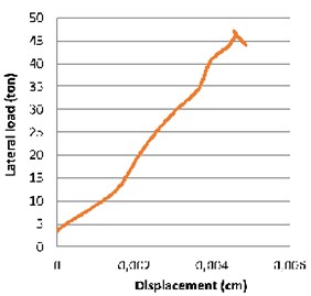
Axial force versus axial displacement curve of the RC column and general aspect of the column after the rupture are shown in Fig. 1.
Fig. 1Section area and force- displacement graph of the laboratory column (C15) [8]
![Section area and force- displacement graph of the laboratory column (C15) [8]](https://static-01.extrica.com/articles/18560/18560-img1.jpg)
3.2. Valid-model
Based on the nature of the load condition, static Riksanalysis is used. This method is an increasing static nonlinear analysis, used for problems where geometric or material non-linearity or contact conditions cause the instability of the structures.
3.2.1. Results comparison
As explained before, axial force versus axial displacement curve of numerical modeling by concrete damage plasticity has been presented and compared with the laboratory results Fig. 2. According to following graphs, the laboratory results show acceptable adjustments compared with the numerical ones.
4. Description of finite element models
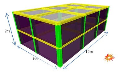
A two- span frame of the supposed building was selected, as shown in Fig. 3. The assumption is that the bomb with the capacity of 100 kg TNT is exploded at 10 meters of the building.
The models are considered in three categories. The first category consists of one model, concrete frame which is reinforced by steel longitudinal bars and stirrups without any external reinforcement, named “RC-model”. The second category consists of three models: i) concrete frame with steel longitudinal bars and stirrups, the columns of which are confined by CFRP sheets, ii) concrete frame with steel longitudinal bars and stirrups, the connections of which are confined by CFRP sheets, and iii) reinforced concrete frame which is completely confined by CFRP sheets. These three models are named “CF-COL model”, “CF-CON model” and “CF-COM model”, respectively.
Fig. 2Force-displacement curves of experimental instances compared with numerical modeling
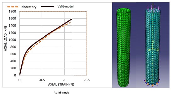
Fig. 3View of the supposed building
The third category consists of three models: i) concrete frame with steel longitudinal bars and stirrups, the columns of which are confined by GFRP sheets, ii) concrete frame with steel longitudinal bars and stirrups, connections of which are confined by GFRP sheets, and iii) reinforced concrete frame which is completely confined by GFRP sheets. These three models are named “GF-COL model”, “GF-CON model” and “GF-COM model”, respectively. In all the models, the thickness of the CFRP/GFRP sheets is 0.2 mm and the position of the longitudinal bars and stirrups is constant.
Fig. 4Typical view of the frame
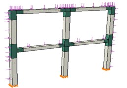
a) CF-CON or GF-CON
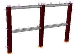
b) CF-COL or GF-COL
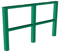
c) CF-COM or GF-COM
In Fig. 4 the typical frame modeled in ABAQUS [9] is represented. As shown in this figure, the supposed frame has two spans with 4.5 m width and two floors with 3.5 m height. Natural period of structure is estimated 0.5 sec. Φ10 and Φ20 used for reinforcing the beams and columns as stirrups and longitudinal rebars, respectively.
Material properties which are used for rebars and external reinforcement sheets are represented in Table 2.
Compressive strength of concrete is 50 MPa and the frame is designed based on ACI318-2014 [19] guideline. A section of beams and columns of the frame is shown in Fig. 5.
Fig. 5Section of beams and columns of the frame
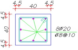
a) Section of beams
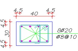
b) Section of columns
Table 2Mechanical properties of the materials
Ult. Tensile strength | Ult. Tensile strain (%) | Modulus of elasticity (GPa) | |
Steel bars | 400 MPa | 2.5 | 200 |
CFRP sheets | 6200 GPa | 1.5 | 240 |
GFRP sheets | 4140 GPa | 4.5 | 90 |
5. Blast loading
The model is subjected to the external surface burst of a bomb with 100 kg TNT, which is placed on the ground 10 m in the front wall of the building. Using the graph which is represented in “handbook for blast-resistant design of building” [20], various parameters of the explosive load have been calculated. According to the base values of external explosion, the forces exerted on the various aspects of the structure are calculated. In order to simplify the exponential change of blast load versus time, it is considered in the triangular form. Table 3 shows the derivations of the explosive loading. In this table , and represent the scaled distance, the peak incident overpressure and the peak dynamic pressure, respectively. shows time duration, , , and indicate distance to the explosion, wave length, effective peak overpressure and incident impulse, respectively. Fig. 4 also shows how the load is applied to the frame.
Table 3Blast load parameters
(ft) | (ft/lb1/3) | (psi) | (psi) | (ft) | (ms) | (psi-ms) | (psi) | |
The front wall | 32.8 | 5.02 | 40 | 28 | 20.52 | 10.26 | 60.37 | 68 |
The side wall | 47.56 | 7.87 | 17 | 6 | 21.8 | 12.98 | – | 8.85 |
Roof | 32.8 | 5.02 | 40 | 28 | 20.52 | 10.26 | – | 13.4 |
The rear wall | 62.32 | 10.32 | 6.5 | 0.98 | 22.82 | 16.9 | – | 2.91 |
6. Method of analysis
For the analysis of the models, explicit dynamic analysis has been used according to the nature of the explosive loads. In this method, large numbers of very small-time steps are carried out effectively and time integration rule with central difference operator is used. In this analysis, displacements and velocities are calculated at each step.
As opposed to implicit analysis, there is no need to calculate the mass and stiffness matrices at each step. This led to reduce the time of integration. It should be mentioned that this method of analysis is perfect for dynamic phenomena that occur very fast, such as collisions, explosions, or impact loads or non-linear problems in which the contact conditions change, such as shaping. Earlier researches proved that the concrete damage plasticity will show the behavior of the concrete reliably [21], so this nonlinear behavioral model is used for concrete. The elements types are the same as those described in the validation section.
7. Results of analysis
7.1. Failure investigation
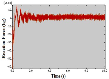
For investigation of shear failure, shear strength of concrete frame was estimated according to ACI318-2014 and compared to stresses derived from ABAQUS analysis. In addition, stresses in rebar and in concrete frame were compared to allowable stress of rebar and flexural strength of concrete frame according to ACI318-2014 to estimate flexural failure. It seems that during the explosive blast, prevention of shear failure in building components, particularly columns are very noticeable in the first moments and over the time control of the flexural failure becomes more significant. This can be justified by the high rate of loading. Fig. 6 and Fig. 7 exactly show that by ten times increase of time of analysis the column high reaction force tends to zero. This shows the importance of the existence of an obstacle to prevent direct collision of the explosive waves, especially for the columns of the structure, and consequently, prevention of direct shear failure which occurred as a result of significant force generated in a very short time.
Fig. 6Shear in base of column due to explosion of a bomb with capacity of 100 kg TNT at time t= 1 sec
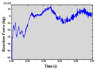
Fig. 7Shear in base of column due to explosion of a bomb with capacity of 100 kg TNT at time t= 10 sec
7.2. Energy absorption
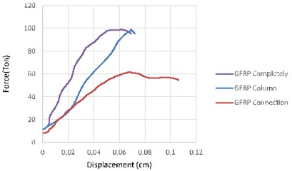
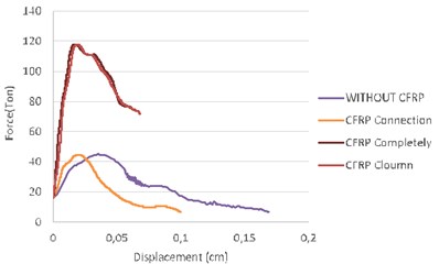
Comparing the areas under the force-displacement curves shows little difference between the model with full external reinforcement and the model the columns of which are only confined with CFRP/GFRP sheets. Energy absorption significantly decreases when only connections have been strengthened. Fig. 8 shows this fact.
Comparing CFRP/GFRP reinforcing shows the models confined by CFRP had more ability to damp explosive energy relative to GFRP strips.
Reinforcing columns with CFRP/GFRP sheets can cause delay in the formation of plastic joint by decreasing the movement of middle span and so causes prevention of the flexural failure or delay.
External strengthening of the full frame in addition to reducing the displacement of the mid columns can cause reduction of displacement of the mid beams.
By strengthening frame connections, displacement of mid columns increases compared to the other cases, but displacement of the mid beams and as a result rotation of connections has decreased. Comparisons of the frames drifts in different situation are shown in Table 4. This table explains that external reinforcement by CFRP layers could experience more stress before failure rather than the model confined by GFRP layers.
Fig. 8Force-displacement curves
a)
b)
Table 4Comparing frame drifts in different cases due to the explosion of bomb with 100 kg TNT
Frame | Drifts |
Non-reinforced | 0.169 cm |
GFRP column reinforced | 0.072 cm |
GFRP fully reinforced | 0.069 cm |
GFRP connections reinforced | 0.106 cm |
CFRP column reinforced | 0.068 cm |
CFRP fully reinforced | 0.061 cm |
CFRP connections reinforced | 0.099 cm |
Table 5 shows that the maximum force generated in the CFRP/GFRP sheets has been reduced by increasing the number of layers. Also, it indicates that CFRP layers show more strength against explosive loads. Figs. 9 and 10 compare the difference of force-displacement diagram of “CF-CON model” which is reinforced by two and four layers of CFRP. These figures represent that increasing the layers of the external reinforcing causes negligible differences in the frame displacement while leading to decrease in the maximum force.
Fig. 9Force-displacement of “CF-CON model” reinforced by two layers of CFRP
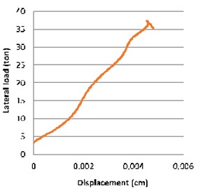
Fig. 10Force-displacement of “CF-CON model” reinforced by four layers of CFRP
7.3. Investigation of Von Mises stress
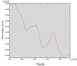
S11 is an indicator of longitudinal stress in CFRP/GFRP strips and S22 represents transverse stress in CFRP/GFRP strips which is in direction of the column longitudinal axis. A few studies have been conducted in the evaluation of pasting CFRP/GFRP strips in longitudinal direction of the column. Here, comparing the capability of these layers in the both directions is carried out by presenting some graphs (Figs. 11-14).
Table 5The maximum stress in the CFRP/GFRP sheets
Number of layers | Stress values (Kg/cm2) | |
CFRP | 1 | 1500 |
2 | 729 | |
4 | 537 | |
GFRP | 1 | 1410 |
2 | 550 | |
4 | 486 | |
Fig. 11S11 diagram of CFRP strip which is placed on a side of the column which is in front of the explosive load
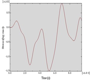
Fig. 12S11 diagram of CFRP strip which is placed on the back side of the column behind the explosive load
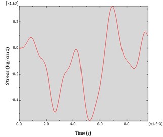
Fig. 13S22 diagram of CFRP strip which is placed on a side of the column which is in front of the explosive load
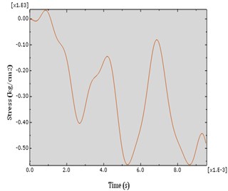
Fig. 14S22 diagram of CFRP strip which is placed on the back side of the column behind the explosive load
8. Conclusions
In this research, a concrete frame is modeled and reinforced by CFRP/GFRP sheets which are subjected to explosive load. Total results obtained are listed in the following:
1) External reinforcement of the frame by CFRP/GFRP layers increased energy absorption up to three times. Models confined by CFRP layer show about 20 % increase in energy absorption compared with those confined by GFRP strips. In this case, there is a negligible difference between the models completely confined and the models only the columns of which are confined. On the other hand, the models only the connections of which had external reinforcements show less ability in damping energy similar to the models without external reinforcement.
2) By increasing the layer of reinforcement energy absorption increased, maximum force generated in the layers decreased and there was no difference in the amount of the displacement.
3) Generally, using CFRP/GFRP layer led to increase strength of the system, as the drift of the frame decreased in this condition. By confining whole of the frame, drift will decrease about 59 % compared with the model without external reinforcement.
4) In the “RC-model”, which does not have external reinforcement, crack has dispersed in a certain direction, as there is a potential of total fraction under the more severe explosion. In the models with strengthened columns, fraction is restricted to the connections.
5) Pasting CFRP/GFRP sheets on the column in the both directions may be more helpful because of significant stresses.
References
-
Teng J. G., Chen J. F., Smith S. T., Lam L. FRP Strengthened RC Structures. John Wiley and Sons, Chichester, 2002, p. 245.
-
Buchan P. A., Chen J. F. Blast resistance of FRP composites and polymer strengthened concrete and masonry structures – a state-of-the-art review. Composites: Part B, Vol. 38, 2007, p. 509-522.
-
Design Guidance for Strengthening Concrete Structures Using Fiber Composite Materials. TR 55, 2nd Ed., Concrete Society, Berkshire, UK, 2004.
-
Parretti Renato, Nanni Antonio Axial testing of concrete columns confined with carbon FRP: effect of fiber orientation. 2004.
-
Hadi M. N. S. Behavior of FRP strengthened concrete columns under eccentric compression loading. Composite Structures, Vol. 77, 2007, p. 92-96.
-
Jankowiak Tomasz, Ladygowski Tomasz Identification of parameters of concrete damage plasticity constitutive. Civil and Environmental Engineering, Vol. 12, 2005, p. 53-69.
-
Benzaid Riad, Chikh Nasr-Eddine, Mesbah Habib Behavior of square concrete column confined with GFRP composite warp. Journal of Civil Engineering and Management, Vol. 14, Issue 2, 2008, p. 115-120.
-
Chastre Carlos, Silva Manual A. G. Monotonic axial behavior and modeling of RC circular columns confined with CFRP. Engineering Structures, Vol. 32, 2010, p. 2268-2277.
-
ABAQUS: Theory Manual (Version 6.10). ABAQUS Inc., 2008, USA.
-
Mark P. Investigations of Reinforced Concrete Girders under Biaxial Shear Using Parametric Finite Element Models. Computational Modeling of Concrete Structures (EURO-C 2006). Taylor and Francis/Balkema, Leiden, 2006, p. 739-746.
-
Bender M., Mark P. Shear bearing capacities of RC beams with circular sections: computational modeling and design. Proceedings of the 8th International Conference on Computational Structures Technology (CST 2006), Scotland, 2006, p. 289-290.
-
Kachanov L. M. Introduction to Continuum Damage Mechanics. Kluwer Academic Publisher, Dordrecht, 1990.
-
Lubliner J., Oliver J., Oller S., Onate E. A plastic-damage model for concrete. International Journal Solids Structures, Vol. 25, Issue 3, 1989, p. 299-326.
-
Oller S., Onate E., Oliver J., Lubliner J. Finite element nonlinear analysis of concrete structures using a “plastic-damage model”. Engineering Fracture Mechanics, Vol. 35, Issues 1-3, 1990, p. 219-231.
-
Lee H. K., Kim B. R., Ha S. K. Numerical evaluation of shear strengthening performance of FRP sheets/strips and sprayed epoxy coating repair systems. Composites Part B: Engineering, Vol. 39, 2008, p. 851-862.
-
Lee H. K., Ha S. K., Afzal M. Finite element analysis of shear-deficient RC beams strengthened with FRP strips/sheets. Structural Engineering and Mechanics, Vol. 30, Issue 2, 2008, p. 247-261.
-
Yu T., Teng J. G., Wong Y. L., Dong S. L. Finite element modeling of confined concrete-II: Plastic-damage model. Engineering Structures, Vol. 32, 2010, p. 680-691.
-
Mark Peter, Bender Michél Computational modeling of failure mechanisms in reinforced concrete structures. Architecture and Civil Engineering, Vol. 8, 2010, p. 1-12.
-
ACI 318, Building Code Requirements for Structural Concrete (ACI 318-05) and Commentary (ACI 318R-05). ACI Committee 318, American Concrete Institute, Farmington Hills, MI, 2005.
-
Dusenberry Donald O. Handbook for Blast Resistant Design of Buildings. John Wiley and Sons, 2010, p. 484.
-
Shirinzadeh M., Haghollahi A. Performance of shear wall with external reinforcement by CFRP and steel sheets against blast load. Journal of Vibroengineering, Vol. 18, 2016, p. 2735-2743.
