Abstract
For the high-aspect-ratio composite joined-wing UAV, as the geometric nonlinear significant effect, nonlinear aeroelastic analysis method should be applied when study its aeroelastic tailoring method. In the paper, based on the secondary development of MSC/Nastran software with Direct matrix abstraction programme language, with the adopting the multidisciplinary design optimization platform Isight software integrating the MSC/Nastran software analysis, modules of the static aeroelastic analysis, nonlinear static analysis and flutter analysis, a nonlinear aeroelastic tailoring method for high –aspect-ratio composite joined-wing UAV has been presented. Example show that, the method proposed in this paper not only can solve nonlinear aeroelastic tailoring of high-aspect-ratio composite joined-wing UAV problem, but also can be applied to complex engineering structure.
1. Introduction
The joined-wing airplane may be defined as an airplane that incorporates tandem wings arranged to form diamond shapes in both plan and front views [1]. The joined-wing aircraft is an example of an innovative design whose realization depends on integration of structures and aerodynamic design so that requirements for stability and control are balanced with the requirement for light weight and high lift to drag. In recent years, more and more attention is gotten from the researchers gradually [2, 3]. In order to improve the performance, most joined-wing unmanned aerial vehicle (UAV) are made of composite materials. As composite materials can be designed, aeroelastic tailoring of composite joined-wing UAV is possible.
High-aspect-ratio composite joined-wing UAV will produce very serious bending deformation and torsional deformation under the dynamic load of aviation. Its static aeroelastic state relative to the original geometry structure has obvious differences, and exert an important influence on the structure of natural mode of vibration. And then this may cause significant influences upon wing flutter characteristics. Therefore, the hypothesis of small deformation cannot be used in solving aeroelastic problems of high-aspect-ratio joined-wing UAV, geometric nonlinear effect must be considered.
In recent years, scholars domestic and foreign carried out much researches on nonlinear aeroelastic problems above mentioned [4-7], they deemed that we could approach the nonlinear flutter speed through calculating a series of flutter speeds at static aeroelastic equilibrium point of the wing by linearizing.
The ply features of composite material include ply thickness and ply orientation. The purport of aeroelastic tailoring is improving the aeroelastic characteristic through changing ply feature of composite materials. Not only can the aeroelastic tailoring technique overcome the disadvantages brought by aeroelastic, but also this technique can improve the performance of the aircraft through using aeroelastic efficiency, which has become one of the indispensable processes in the modern aircraft design [8-10]. Aeroelastic tailoring began in the 1960s, with the development of computer technology and extensive application of advanced composite materials in the aircraft, the aeroelastic tailoring technique is also in the development. The researcher domestic and foreign obtained many achievements [11-13].
With the geometric nonlinear significant effect, nonlinear aeroelastic analysis method should be applied when study high aspect ratio composite joined-wing’s aeroelastic tailoring design. The research for nonlinear aeroelastic tailoring technique corresponding to analyzing its structure by using nonlinear finite element method has not been seen. In this paper, based on the secondary development of MSC/Nastran software with Direct matrix abstraction programme language [6], with adopting the multidisciplinary design optimization platform Isight software integrating MSC/Nastran software analysis modules of the static aeroelastic analysis, nonlinear static analysis and flutter analysis, a nonlinear aeroelastic tailoring method for high-aspect-ratio composite joined-wing UAV has been presented. As the actual angle of attack in the engineering of high-aspect-ratio joined-wing UAV is less than the stall angle of attack, aerodynamic model in this paper used the doublet lattice method in Nastran.
2. Nonlinear flutter analysis method and theory
Nonlinear flutter speed refers to the critical speed causing the nonlinear aeroelastic system instability. For each given flight Mach numbers, need approach the static aeroelastic steady state, then linearize and calculate flutter speed, until the flight Mach numbers and the flutter speed is equal.
2.1. Static aeroelastic analysis
Static aeroelastic equilibrium point of the wing can be obtained by solving static aeroelastic equation.
The wings lifting surface is discretized and divided into trapezoidal panels, and then it’s aerodynamic influence coefficients(AICs) are calculated. The non-dimension downwash velocity at the collocation point can be written in terms of AICs as:
where are displacement vector of the structure finite element node, is the transformation matrix from structural deflections to the downwash at collocation points, is the downwash at collocation points caused by the initial angle of attack, are the non-dimensional pressures of the lifting elements, is the dynamic pressure of free steam, is the AICs matrix, which is a function of reduced frequency and the free stream Mach number . is the oscillation frequency, is the semi-chord length and is the free stream velocity.
The aerodynamic lift and moment can be written in terms of the structural deflections as:
where is the integrating matrix.
After building the nonlinear FEM model of the wing structure in MSC/Nastran and coupling it with aerodynamic model. The steady AICs matrix and transformation matrix for each Mach number can be extracted from the static aeroelastic analysis module by DMAP tool. The static aerodynamic lift and moment can be written as:
Then using the nonlinear static analysis module, the structural nonlinear equilibrium equation of the restoring force, aerodynamic load can be written as:
where is the restoring force due to the structural nonlinear deformation. The structural deformation under the action of aerodynamic load can be obtained by solving Eq. (4), which is a nonlinear algebraic equation and needs to be solved by iterative loops.
2.2. linearizing and flutter analysis
Ignoring the structural damping, the nonlinear aeroelastic equation of wing can be written as:
The solution of the Eq. (5) can be assumed as follows:
where is the steady state value obtained by solving Eq. (4), is the small perturbation with respect to the equilibra. Therefore, the aeroelastic equation can be linearized at the steady state, given:
where are the mass and stiffness matrixs at state .
The normal modes were calculated for the steady state and then the appropriate modes were chosen to reduce the equation. The aeroelastic equation can be written via the generalized coordinates as:
where is the generalized coordinate array vector, is the generalized mass matrix, is the generalized stiffness matrix, is generalized unsteady aerodynamic force matrix, which is a function of the reduced frequency.
The above matrices were incorporated into MSC/Nastran flutter analysis module by DMAP tool and P-K method is applied to perform flutter analysis. The unmatched flutter velocity and the corresponding flutter Mach number are:
where is local velocity of sound. Comparing to the initial free stream Mach number given at the beginning of the static aeroelastic analysis: If , then is the matched nonlinear flutter speed. Otherwise reset the free stream Mach number and solve Eqs. (4-9) again, until the error is converged.
3. Optimization theory
3.1. Describing in mathematics
In this paper, the nonlinear elastic tailoring of composite materials is a structural optimization problem in principle. from the view of structure optimization, its mathematical model can be summed up as: seeking for design variables within constrain of static and dynamic strength, to maximize the objective function. Therefore, for laminated composite structure often used in aircraft structure, the ply orientations are chosen as design variables:
The flutter speed maximization is chosen as the objective function:
Meanwhile meet constraint function:
Here, the constraint can be stress, strain, displacement, and etc., and the structure parameters of boundary constraints:
3.2. Multi Island genetic algorithm(MIGA)
For the purpose that the result of aeroelastic tailoring can be used in practical engineering structure, design variables in this paper is discrete variables. Discrete variable will inevitably bring about the discrete objective function and constraint conditions. That is to say, the objective function and constraints conditions function are multi-peak, nonlinear, non-continuous and non-differentiable. The genetic algorithm can solve these problems mentioned above effectively.
Genetic algorithm concept was brought out in 1967 by Bagley J. D, and USA Professor J. Holland had done pioneering work in the theory and method in 1975, which aimed to show that the adaptive process between natural and artificial systems. As an intelligent optimization method, the genetic algorithm is an iterative adaptive probability optimization calculation method which is based on the principles of natural selection and natural genetic, to achieve the optimization by simulating biological evolution process [14].
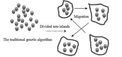
Multi Island Genetic Algorithm(MIGA) is a new algorithm built in the traditional genetic algorithm, which not only is inherit fitness, selection, crossover and mutation theory used in the traditional genetic algorithm, but also introduce the concept of introduction of sub populations and islands. As shown in Fig. 1, a large population is divided into several sub-populations or islands. In each island, traditional genetic populations evolutionary algorithm is used. Meanwhile, the individual of each island is chosen according to a certain proportion of in each island every a few generations then transfers to other islands, this transfer can complete the interchange among populations and increase diversity individual.
This operation is called migration. With the diversity of optimum solutions in each island brought by converging to different local optimum solutions and migration operations, it is more likely to find the global optimum solution in optimization field.
Fig. 1Plot of multi island genetic algorithm
4. Analysis procedures
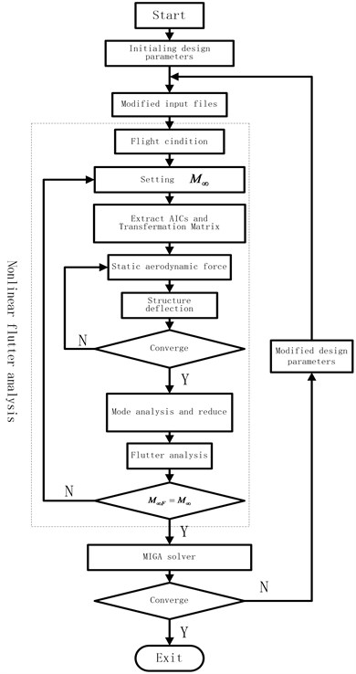
The analysis diagram of present work is shown in Fig. 2. Initial design parameters such as design variables are given before the analysis in Isight software platform. Firstly, modify the calculation of documents with new design parameters. Secondly, obtain the flutter speed with nonlinear flutter analysis process in dashed box. Thirdly, the flutter speed is transmitted to the Island genetic algorithm solver. If the convergence conditions are not met, then modify the design variables, repeat the above procedures. Otherwise, analysis ends.
Firstly, assume the free stream Mach number with the given flight condition parameters such as angle of attack, under this flight condition, the steady AICs matrix and the transform matrix can be obtained using the static aeroelastic module, then calculate static aerodynamic force. Then the structural deflections under the action of aerodynamic loads are calculated by means of nonlinear static analysis module.
In order to approach the steady state, the steady aerodynamic loads are computed again according to new structural deflections. Thus, iterative loop is applied to make the aerodynamic loads match the structural deflections, which finally turn into the actual equilibrium point of wing. Reduced the equations at steady state, incorporate the generalized mass and stiffness matrix into the flutter analysis module and calculate the flutter speed. Repeat the above procedures until the difference between the results and the free stream Mach number is converged. The corresponding flutter speed is defined as the nonlinear flutter speed for this flight condition.
Fig. 2Flow chart of analysis
5. The example
Model of this joined-wing UAV is shown in Fig. 3, its geometric parameters are shown in Table 1. The beams, ribs and skins are made of carbon fiber composite (T300/5222), whose parameters are shown in Table 2. The initial ply orientations of the front wing and the aft wing skins are both [0/0/0/0] s, each ply thickness is 0.216 mm. There are 1116 finite elements in the model. The finite element model and aerodynamic model of this joined-wing are shown in Fig. 4.
Fig. 3Model of joined-wing
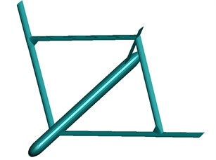
Fig. 4Structural finite element model and aerodymic model
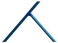
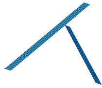
Table 1Geometric parameters of Joined-wing
Parameters | Values |
Span | 60.96 m |
Chord | 2.05 m |
Front wing | 37.45 m |
Root to joint-Front Wing | 24.34 m |
Root to joint-Aft Wing | 24.34 m |
Joint region | 2.76 m |
Joint to tip | 10.35 m |
Sweep angle of front wing | 35° |
Sweep angle of aft wing | 35° |
Dihedral angle of front wing | 6°30′ |
In plane angle between front and aft wing | 70° |
Out of plane angle between front and aft wing | 16° |
Aspect ratio (front wing) | 26.70 |
Table 2parameters of T300/5222
/ GPa· | / GPa | / GPa | / kg·m-3 | |
135 | 9.4 | 0.3 | 5 | 1580 |
Ignoring aeroelastic effects of the fuselage [15], the density of the air is 1.226 Kg/m3. First of all, the initial 5, 8, 10, 11, 12, 13, 14 modes are chosen respectively for the nonlinear flutter analysis. It shows that the wing has the flutter characteristics of multi-modal participation. So, in this paper the initial 12 modes are selected.
With the original design parameters, the result of the nonlinear flutter speed analysis is 115 m/s, corresponding to flutter frequency is 2.1 Hz. v-g curves and v-f curves are shown in Fig. 5.
Based on the models above mentioned, setting ply orientations of the front wing skin and the aft wing skin, in a total of 8, as design variables. These are discrete variables, whose allowing values are –45 degrees, 0 degrees, 45 degrees and 90 degrees, setting the dynamic pressure corresponding to maximum flutter speed as the design object, carry out the nonlinear aeroelastic tailoring by the method mentioned above.
Fig. 5v-g and v-f curves before tailoring
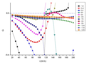
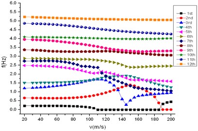
Fig. 6v-g and v-f curves after tailoring
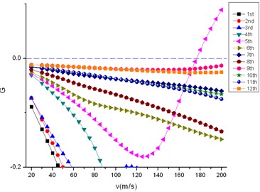
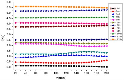
Fig. 7Design object of optimization iteration
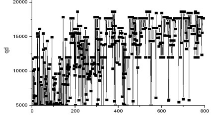
Table 3The result of tailoring
Parameters | Before tailoring | After tailoring |
First ply orientation of front wing skin | 0° | 0° |
Second ply orientation of front wing skin | 0° | 90° |
Third ply orientation of front wing skin | 0° | –45° |
Fourth ply orientation of front wing skin | 0° | –45° |
First ply orientation of aft wing skin | 0° | 45° |
Second ply orientation of aft wing skin | 0° | 90° |
Third ply orientation of aft wing skin | 0° | 45° |
Fourth ply orientation of aft wing skin | 0° | 45° |
Flutter speed | 115 m/s | 175 m/s |
The results of aeroelastic tailoring are shown in Table 3. Nonlinear flutter speed is 175 m/s, corresponding to flutter frequency is 1.92 Hz. V-G curves and V-F curves are shown in Fig. 6. Design object of optimization iteration is shown in Fig. 7.
6. Conclusions
For joined-wing UAV, because of the mutual influence and constraints between the front wing and aft wing, characteristics of the flutter have the feature of multi modal participation.
Analyzing its flutter speed need take into account the effects of higher order modes. The morphological character of flutter is changed by nonlinear flutter optimization; the speed of flutter turns from 115 m/s into 175 m/s by changing the laying orientations of skin. Nonlinear aeroelastic tailoring method mentioned in the paper can remarkably improve its flutter speed, meanwhile the weight of the structure doesn’t increase.
This paper presents an aeroelastic tailoring method with consideration of the nonlinear effects of the joined wing UAV, which can be completed with the existing mature commercial software. The method can be applied to complex engineering structure.
References
-
Wolkovitch J. The Joined Wing-An Overview. AIAA-1985-274, 1985.
-
Weisshaar T. A., Lee D. H. Aeroelastic Tailoring of Joined-Wing Configurations. AIAA-2002-1207, 2002.
-
Nonlinear Aeroelastic Analysis of Joined-Wing Aircraft with Fully Intrinsic Equations. AIAA-2009-2464, 2009.
-
Dowell E., Edwards J., Strganac T. Nonlinear aeroelasticity. Journal of Aircraft, Vol. 40, 2003, p. 857-874.
-
Chen Quanlong, Han Jinglong, Yun Haiwei Flutter analysis of wings subjected to engine thrusts. Journal of Vibration Engineering, Vol. 25, Issue 2, 2012, p. 110-116.
-
Ran Yuguo, Han Jinglong, Yun Haiwei Development of aeroelastic response solution sequence with dmap language for freeplay nonlinear structure. Journal of Nanjing University of Aeronautics and Astronautics, Vol. 39, Issue 1, 2007, p. 41-46.
-
Xie Changchuan, Wu Zhigang, Yang Chao Aeroelastic analysis of flexible large aspect ratio wing. Journal of Beijing University of Aeronautics and Astronautics, Vol. 29, Issue 12, 2003.
-
Shirk M. H., Hertz T. J., Weisshaar T. A. Aeroelastic tailoring-theory, practice and promise. Journal of Aircraft, Vol. 986, Issue 23, 1, p. 6-18.
-
Zhou Congqing Mechanism and benefit of the aeroelastic tailoring. Acta Materiae Compositae Sinica, Vol. 6, Issue 4, 1989, p. 1-9.
-
Weisshaar T. A., Nam C., Batista R. A. Aeroelastic Tailoring for Improved UAV Performance. AIAA-98-1757, NewYork, 1998.
-
Dillinger J. K. S., Klimmek T., Abdalla M. M., Gürdal Z. Stiffness optimization of composite wing with aeroelastic constraints. Journal of Aircraft, Vol. 50, Issue 4, 2013, p. 1159-1168.
-
Zhou Lei, Wan Zhiqiang, Yang Chao Effect of laminate parameters of composite skin on aeroelastic optimization of high-aspect-ratio wing. Acta Materiae Compositae Sinica, Vol. 30, Issue 5, 2013, p. 195-200.
-
Liu Xiangning, Xiang Jinwu Study of aeroelastic tailoring of high-aspect ratio flexible composite wing. Journal of Beijing University of Aeronautics and Astronautics, Vol. 32, Issue 12, 2006, p. 1403-1407.
-
Li Chunming Optimization Method. Southeast University Press, Nanjing, 2009.
-
Zhang Shujun, Wang Yuntao, Meng Dehong Study on static aeroelasticity for high-aspect-ratio joined-wings. Acta Aerodynamica Sinica, Vol. 32, Issue 2, 2013, p. 170-174.
