Abstract
A spherical ultrasonic motor for space has been developed by this investigation. Development results of the spherical ultrasonic motor which can be driven under the high temperature environment of the atmospheric pressure were described by previous paper. The results about developed spherical ultrasonic motor which was investigated in the environment of low temperature and temperature cycle are described by this paper. First, it was confirmed that the spherical ultrasonic motor drives in low temperature environment of −120 °C. When durability tests for the spherical ultrasonic motor were carried out in temperature of −80 °C, approximately 60 minutes as accumulated drive time was achieved. Further, freezing phenomenon occurred on a sliding surface between stator and spherical rotor of the spherical ultrasonic motor, and drive of the spherical ultrasonic motor was disturbed. Next, when a drive experiments about the temperature cycle were carried out, influence of the temperature cycle to a torque was small. It was confirmed that the rotational speed decreases by the decline of piezoelectric of a piezoelectric element and the decline of the hardness of the adhesive to which a piezoelectric element and an elastic body are attached in high temperature environment. On the other hand, it was confirmed that the rotational speed decreases by the freezing which occurs on the sliding surface and the influence of the characteristic of the piezoelectric element in low temperature environment.
1. Introduction
In recent years, development of space is promoted actively, and a launch of an artificial satellite and a space probe is carried out energetically. There is much equipment using an actuator like a solar paddle, an antenna and an optical mirror for observations in a spacecraft. On the other hand, thrusters which attaches to an artificial satellite are not using an actuator. The thrusters used for attitude control and course correction are be equipped with by an artificial satellite, but it is a cause of weight increase. When the direction of the thruster can be controlled by an actuator, a thruster is integrated, and an artificial satellite is reduced the weight of. So, a spherical ultrasonic motor (hereinafter referred to as SUSM) for space used for the direction control of a thruster has been developed by this investigation. The SUSM with 3-DOF is suitable for the direction control of an integrated thruster. The ultrasonic motor [1, 2] is applied in a wide area and is investigated by many researchers [3-5]. In particular, it is expected that the SUSM [6-9] is applied to medical devices [10] and robot hand [11], etc. However, the example to which the ultrasonic motor is applied in the space is not found.
An artificial satellite is exposed to high and low temperature by receiving radiant heat from the sun and entering the shadow of the earth in space. Therefore, the SUSM for space has to be driven by both of high temperature environment and low temperature environment. For example, a performance test to equipment for space by Japan Aerospace Exploration Agency (JAXA) is carried out by the temperature cycle during ±120 °C.
The drive experiment in vacuum environment of standard temperature [12] and the drive experiment in high temperature environment (from standard temperature to +120 °C) of the atmospheric pressure [13] were carried out by the previous investigation about development of the SUSM for space. In particular, the piezoelectric element and the adhesive which function in high temperature environment were selected, and the SUSM for space using those was experimented on durably. Then, the purposes of this investigation are to experiment on the drive and the durability in low temperature environment (from standard temperature to −120 °C) of the atmospheric pressure and to evaluate the piezoelectric element and the adhesive selected by high temperature environment. It is also the purpose to investigate drive performance of the SUSM in the environment with the temperature cycle of the atmospheric pressure.
2. Piezoelectric element and adhesive used for SUSM
2.1. Outline of SUSM
The SUSM with 3-DOF used by this investigation is indicated on Fig. 1. The SUSM consists of three ring-shaped stators and a spherical rotor holding by these stators. The sizes of the stator and the spherical rotor are diameter 30 mm and diameter 45 mm respectively. These sizes are proper as the SUSM used for a thruster. The stator is the structure by which a piezoelectric element was stuck by adhesive on an undersurface of a metallic elastic body (see Fig. 2).
Fig. 1Photograph of SUSM
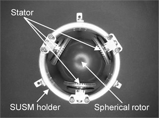
Fig. 2Generation mechanism of traveling wave on stator
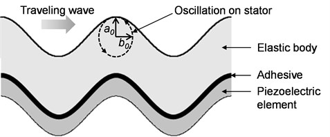
A drive source of ultrasonic motor is mechanical oscillation of the ultrasonic region over 20 kHz. When the alternating current volts of the high frequency are impressed on the piezoelectric element, a traveling wave generates on the stator. The spherical rotor touches each stator and drives by receiving frictional force. When rotation vector of drive force by each stator is compounded about three stators, a spherical rotor can revolve by any rotating shaft. The direction of rotation is controlled by establishing the phase difference to the alternating current volts of two input sine waves to each stator.
2.2. Selected piezoelectric element and adhesive
The piezoelectric element and the adhesive which can drive SUSM in high temperature environment of +120 °C were considered by the previous investigation. N6 piezoelectric element (made by NEC/TOKIN Co.) by which the Curie temperature is 325 °C was selected in a piezoelectric element, and adhesive TB2285 (made by Three Bond Co., Ltd) by which the glass transition temperature is 185 °C was selected in an adhesive. It is considered by this investigation that the performance of the N6 piezoelectric element and the adhesive TB2285 selected for high temperature environment is also maintained in low temperature environment.
2.3. Influence to piezoelectric element of low temperature environment
An ultrasonic motor is driven by a traveling wave which generates to a stator, and the frictional force which generates by contact of the stator oscillating by the traveling wave and the spherical rotor is the drive source of the spherical rotor. Oscillation on the stator is an elliptical orbit as shown in Fig. 2. And the amplitude of the vertical oscillation and the horizontal oscillation is a0 and b0 respectively.
The definition of torque T0 generated from each stator is indicated in Eq. (1):
where, μ is the friction coefficient between the spherical rotor and the stator, R is the radius of the stator, and N0 is the pressing power between the spherical rotor and the stator. The pressing power is proportional to the amplitude of the vertical oscillation of the traveling wave, and when the amplitude of the vertical oscillation is big, the pressing power becomes strong. And the rotational speed of the spherical rotor is proportional to the amplitude of the horizontal oscillation, and when the amplitude of the horizontal oscillation is big, the rotational speed is increased.
The definition of the amplitude of the vertical oscillation is indicated in Eq. (2):
where, Cv is the speed of sound transmitted in the elastic body, ρ is the density of the elastic body, t is the thickness of the piezoelectric element, fr is the resonant frequency of the piezoelectric element, d is the piezoelectric constant, Yd is the Young’s modulus of the piezoelectric element, and Vin is the voltage impressed on a piezoelectric element.
The piezoelectric constant of Eq. (2) is a strain by giving an electric field to the piezoelectric element, and is expressed in Eq. (3):
where, K31 is the electromechanical coupling coefficient, and ε is the permittivity of a piezoelectric element. Further, the electromechanical coupling coefficient is the fixed number which shows the electrical energy added during a pole of piezoelectric substance as the efficiency changed to the mechanical energy.
The electromechanical coupling coefficient and the permittivity in Eq. (3) are expressed in Eq. (4) and Eq. (5) respectively:
where, fa is the anti-resonance frequency of the piezoelectric element, C is the capacitance of the piezoelectric element, and S is the area of the piezoelectric element.
The speed of sound transmitted in the elastic body and the Young's modulus in the Eq. (2) is expressed in Eq. (6) and Eq. (7) respectively:
where, G is the modulus of rigidity of the elastic body, and l is the length of the circumferential direction of the piezoelectric element.
Therefore, the amplitude of vertical oscillation in Eq. (2) is shown like Eq. (8) from Eq. (3) and Eq. (5)-Eq. (7):
The length of the circumferential direction, the thickness and the area of the piezoelectric element in Eq. (8) are the individual value for which it is difficult to be depended on the temperature for. Therefore, when the temperature changes, the electromechanical coupling coefficient, the capacitance and the modulus of rigidity of the elastic body are the physical quantity which influences the amplitude of vertical oscillation.
As reference, a rough estimate of the amplitude of vertical oscillation in standard temperature (approximately 20 °C) and low temperature (approximately −80 °C) is tried using the electromechanical coupling coefficient, the capacitance, and the modulus of rigidity of the elastic body of known data. The electromechanical coupling coefficients in standard temperature (20 °C) and low temperature (−80 °C) are 16.2 % and 12.9 % respectively, and the capacitances are 3000 pF and 2460 pF respectively. Because the main ingredient about an elastic body of a piezoelectric element is a phosphor bronze, the modulus of rigidity of the phosphor bronze in standard temperature (22 °C) and low temperature (−78 °C) are 40.2 GPa and 42.7 GPa respectively. When these numerical values are substituted for Eq. (8), the amplitude of vertical oscillation can get approximately 0.7 in low temperature to 1 in standard temperature. The amplitude of vertical oscillation in low temperature (approximately −80 °C) decreases approximately 30 % compared with standard temperature (approximately 20 °C).
On the other hand, a relation of subordinate proportion is between the amplitude of vertical oscillation and the amplitude of horizontal oscillation. Therefore, because the amplitude of the vertical oscillation and the horizontal oscillation of the elliptic orbit which generates on the stator is reduced by a decline of the temperature, a decline of the temperature is considered as the factor which causes decrease of the pressing power and the rotational speed.
2.4. Influence to adhesive of low temperature environment
The performances necessary to the adhesive are the shear strength after indurating, the size of the peel strength, and the level of the hardness after indurating. These performances should be maintained in low temperature environment. Adhesive TB2285 used for N6 piezoelectric element of the SUSM for space is the epoxy resin of the thermosetting. The performance of the adhesive is lost by dissolution and detaching in high temperature environment beyond the glass transition temperature (180 °C) and the pyrolysis temperature of the epoxy resin (250 °C-350 °C). And because the performance of the adhesive does not change when there is no use of a solvent or heating to the glass transition temperature in indurating later, the available upper limit temperature is the glass transition temperature. On the other hand, each glass transition temperature and the combination percentage of the high polymer materials influence the performance of the adhesive, but there is not a lot of data of thermal performance in low temperature environment. Then influence of temperature to the shear strength, the peel strength, and the hardness of the adhesive using the epoxy resin is considered.
The epoxy resin is generally the big modulus of elasticity, and it is hard and fragile. The shear strength is proportional to the modulus of elasticity of the adhesive, but the peel strength is in inverse proportion to that. In other words, a relation of a trade-off is between the shear strength and the peel strength. The adhesive should be applied thick to strengthen the peel strength. But because a gap is limited for the adherend inside the piezoelectric element, performance improvement of the peel strength is limited. Therefore, the important performance of the adhesive used for SUSM is the shear strength. The shear strength and the peel strength of the adhesive by which single epoxy resin is an ingredient do not change from low temperature (−73 °C) to high temperature (149 °C). In particular, the strength shear maintains the strength from −253 °C of low temperature to 150 °C of high temperature. Therefore, the shear strength and the peel strength of adhesive TB2285 are also maintained in low temperature environment like high temperature environment. On the other hand, for the general material to increase the hardness in low temperature, it is guessed at that the adhesive TB2285 also increases the hardness in low temperature. When it is based on the above, it is considered that the performance of the adhesive TB2285 is also maintained in low temperature environment.
3. Performance evaluation of SUSM in low temperature environment
3.1. Measuring method of rotational speed
The experimental equipment used by this investigation is indicated on Fig. 3. The drive direction of the SUSM is restricted by the guide-rail and the guide bar. The guide bar is reciprocated at range of 110 deg along guide-rail. This driving method gives the biggest load to SUSM. The cycle experiment by which drive for 20 seconds and a stop for 10 seconds are repeated was carried out and the change in the rotational speed to the accumulated drive time was measured. The rotational speed is calculated from the animation. The temperature of the stator was measured using K type thermocouple during drive. And an impedance of the piezoelectric element on the stator using an impedance analyzer (4294A made by Agilent Technologies, Inc.) was measured.
Fig. 3Experimental equipment for drive experiment
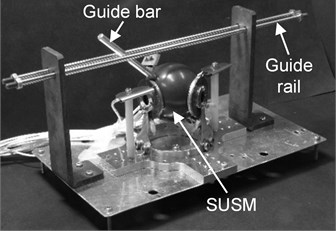
A gas injection type thermostat oven (TCL-N382 made by Shimadzu) was used for the experiment in low temperature environment. Temperature change from −180 °C to +320 °C is possible by this equipment. The thermostat oven is heated by an internal heater and is cooled by injection of liquid nitrogen gas. The temperature in the thermostat tank is kept within ±1.0 °C to a temperature setting. The accessory software of the thermostat oven was used for temperature control. The size in the thermostat oven is height 600 mm, width 382 mm and depth 382 mm. The experimental equipment indicated on Fig. 3 was installed in the thermostat oven by this investigation. The SUSM inside the thermostat oven is connected to the motor driver and the motor controller in the outside by a cable. The cable passes through the small hole in the thermostat oven underside. To drive the SUSM by impressing of a resonant frequency, the exclusive motor driver has the function which searches a resonant frequency automatically.
3.2. Temperature setting of low temperature environment
Low temperature environment of this investigation is achieved by cooling in the thermostat oven by liquid nitrogen gas. And, when the temperature was less than −80 °C, the phenomenon which disturbs drive of the SUSM by a freezing which occurred between the stator and the spherical rotor was observed. It is considered as the cause of the freezing that outside air including humidity flows in from a gap of the thermostat oven underside or that outside air including humidity is added to cold gas for temperature control.
On the other hand, when the SUSM is driven, the spherical rotor rotates, and the stator generates the heat by oscillation. So, the freezing is generated during stopping the SUSM, and the freezing is melted during driving the SUSM. However, when the temperature in the thermostat oven was less than −80 °C, the freezing stayed behind, and drive of the SUSM is disturbed by the freezing. And the drive of the SUSM could be confirmed in −120 °C of the target temperature, but the SUSM was stopped several minutes later because the freezing also stayed behind during drive the SUSM. Therefore, the lowest limit temperature as low temperature environment was defined in −80 °C of the temperature which does not influence drive of SUSM by this investigation. However, it is guessed at that the freezing is also carefree in low temperature environment, because an actual space environment is dry.
3.3. Results of measurement of rotational speed
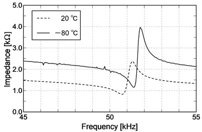
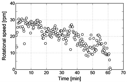
Impedance of 20 °C and −80 °C are indicated on Fig. 4. It is understood to maintain piezoelectric because sharpness of the impedance curved line is not lost in low temperature environment of −80 °C like room temperature of 20 °C. The rotational speed of the SUSM in low temperature environment of −80 °C is indicated on Fig. 5. The accumulated drive time of the SUSM was 61 minutes and 20 seconds.
Fig. 4Comparison of impedance characteristics
Regarding Fig. 5, it is considered below about that the rotational speed of the SUSM was decreased and that the SUSM was stopped in 61 minutes and 20 seconds. There are major causes of two. As the first, it is considered that the difference has been caused between the true resonant frequency of the piezoelectric element and the resonant frequency searched automatically because the temperature difference was generated in the phase A, phase B and phase FB of the piezoelectric element. As the second, it is considered that the freezing which stayed behind had an influence because the freezing which has occurred to a gap of the stator and the spherical rotor by reciprocation limited in the drive direction could not be melted by heat.
Fig. 5Rotational speed at −80 °C
4. Performance evaluation of SUSM in temperature cycle
An artificial satellite is exposed to high temperature environment and low temperature environment by surrounding on the orbit. Then, the outside of the artificial satellite has a hot place and a cold place by the posture of the artificial satellite. The SUSM used at space receives the temperature cycle with the big temperature difference. The performance of the SUSM by influence of the temperature cycle is estimated at this chapter.
4.1. Influence of temperature cycle to stator
When the material is the laminated structure, an adjustment about the coefficients of thermal expansion of each material is important by the environment with the temperature cycle. When laminating material different in the coefficient of thermal expansion during the material receives a thermal pulse like the temperature cycle of the short time, a crack occurs to bonded surface of laminating material.
The stator of the SUSM is the laminated structure which consists of the elastic body, the N6 piezoelectric element and the adhesive TB2285. The material of the elastic body is a phosphor bronze and the coefficient of thermal expansion is 18.2×10⁻⁶ /°C. The main ingredient of N6 piezoelectric element is a zircon acid titanic acid lead, and the coefficient of thermal expansion is 1.2×10⁻⁶ /°C. The coefficient of thermal expansion of adhesive TB2285 is 33.0×10⁻⁶ /°C. It is considered that the SUSM for space is weak in a thermal pulse because the coefficient of thermal expansion of each material of tshe SUSM for space is different.
4.2. Influence of temperature cycle to rotational speed
To estimate influence of the temperature cycle to the rotational speed, the same experimental equipment as Fig. 3 was used. The range of the temperature change was from −80 °C to 120 °C, and the rotational speed of the SUSM was measured every 10 °C. The temperature cycle was divided into three stages. At the first stage, the temperature rose from 20 °C to 120 °C by using the internal heater. At the next stage, the temperature was descended in from 120 °C to −80 °C by liquid nitrogen gas. At the last stage, the temperature rose from −80 °C to 20 °C by using the internal heater. Temperature change was assumed 1.6 °C/min of low speed. The total time of the temperature change was approximately 12 hours including measurement time. The calculation method of the rotational speed is like Section 3.1.
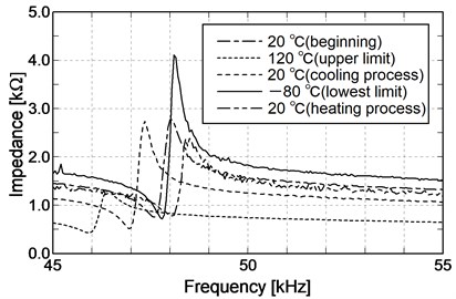
Impedance of the piezoelectric element of the stator was measured in each temperature using the impedance analyzer. Impedance was measured by the following five temperatures respectively; 20 °C of the room temperature when beginning, 120 °C of the upper limit temperature, 20 °C of the room temperature included in cooling process from 120 °C to −80 °C, −80 °C of the lowest limit temperature, and 20°C of the room temperature in the end of heating process from 80 °C to 20 °C. The results of measurement of impedance are indicated on Fig. 6. Because sharpness of the impedance curved line is observed in the measured temperature, it is understood to maintain piezoelectric. And there is a little difference in the resonance frequency and the anti-resonance frequency about 20 °C of the room temperature which was measured 3 times during the temperature cycle. However, because the peak value of the impedance is observed, there are no problems.
Fig. 6Comparison of impedance characteristics in temperature cycle
The results of measurement of the rotational speed are indicated on Fig. 7. When it was heated from 20 °C of the room temperature, the high rotational speed was maintained. And when it was more than 100 °C, the rotational speed was decreased suddenly. When it was cooled from 120 °C of the upper limit temperature, the rotational speed became high again. And when it was less than 0 °C, the rotational speed was decreased. The rotational speed in the low temperature environment indicated the fixed low numerical value which has no dependence of the temperature. When the temperature rose again, it was confirmed that the rotational speed turns back.
Fig. 7Rotational speed in temperature cycle
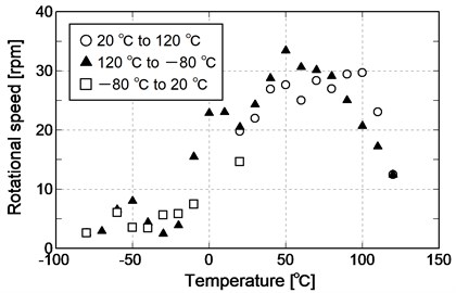
The causes of the decrease of the rotational speed in the high temperature environment are considered according to a decline of piezoelectric of a piezoelectric element and a decline of the hardness of the adhesive which attaches the piezoelectric element to the elastic body. The glass transition temperature is 180 °C for adhesive TB2285 which is used by this investigation, and the ambient temperature does not reach the glass transition temperature by 120 °C. On the other hand, when the voltage is impressed on a piezoelectric element, heat is caused. It is considered that the hardness of the adhesive fell because the temperature of the adhesive rose locally by this heat.
The causes of the decrease of the rotational speed in the low temperature environment are considered according to the freezing which occurs on the sliding surface and the characteristic of the piezoelectric element. As it was described at Chapter 2, when each numerical value of the electromechanical coupling coefficient, the capacitance and the modulus of rigidity of the elastic body undergo influence of temperature change, the a0 of vertical oscillation is smaller than the value of the room temperature. And it is predicted that b0 of the horizontal oscillation is also proportionally smaller than the value of the room temperature. Therefore, it is considered that the rotational speed decreased by reduction of the horizontal oscillation.
4.3. Influence of temperature cycle to torque
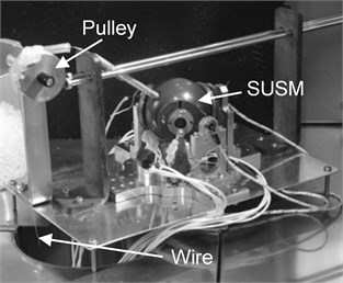
To estimate influence of the temperature cycle to the torque, a pulley was added to the experimental equipment of Fig. 3. The experimental equipment with the pulley is indicated on Fig. 8. One end of a wire was installed in the guide bar, and another end of a wire was installed in the spring balance in the outside from the thermostat oven underside through the pulley. The load of driving the SUSM was measured using the spring balance and the load torque was calculated. The maximum load of the spring balance is 1.1 N, and the minimum scale is 0.02 N. To use the spring balance of outside of the thermostat oven, a part of the thermostat oven underside was opened by this measurement. When a part of the thermostat oven underside was opened, the SUSM was caused freezing in less than −50 °C like Section 3.2. Therefore, the lowest limit temperature in the low temperature environment is −50 °C without influence of freezing by this experiment. Influence of the temperature cycle to the torque was estimated in the range of the temperature change from −50 °C to 120 °C.
Fig. 8Experimental equipment for measurement of torque
The temperature cycle was divided into three stages. At the first stage, the temperature rose from 20 °C to 120 °C by using the internal heater. At the next stage, the temperature was descended in from 120 °C to −50 °C by liquid nitrogen gas. At the last stage, the temperature rose from −50 °C to 20 °C by using the internal heater. Temperature change was assumed 1.0 °C/min of low speed. The total time of the temperature change was approximately 6 hours including measurement time. Torque was measured by the following five temperatures respectively; 20 °C of the room temperature when beginning, 120 °C of the upper limit temperature, 20 °C of the room temperature included in cooling process from 120 °C to −50 °C, −50 °C of the lowest limit temperature.
Load torque in each temperature is indicated in Table 1. Decrease of the torque was observed by 120 °C of the upper limit temperature. However, a big torque change was not observed by 20 °C of the room temperature and −50 °C of the lowest limit temperature. Therefore, it is supposed that the stable torque is obtained from the room temperature environment to the low temperature environment without freezing and that the stable torque is obtained when the environment returns to room temperature again even if the torque is decreased in high temperature environment.
4.4. Evaluation about characteristic of torque - rotational speed
Weights are installed in the wire of the experimental equipment indicated on Fig. 8 by measurement about the characteristic of the torque-rotational speed. The rotational speed to the torque was measured by changing the mass of the weight. The mass of the weight is from 0 g to 35 g every 5 g. The rotational speed was calculated from reciprocation of the guide bar along the guide-rail indicated on Fig. 8. These experiments were carried out in 20 °C of the room temperature, 120 °C of the upper limit temperature and −50 °C of the lowest limit temperature.
Table 1Measurement results of torque in temperature cycle
Temperature °C | Torque mNm |
20 (20 to 120 °C) | 12.5 |
120 | 6.0 |
20 (120 to −50 °C) | 11.5 |
−50 | 13.3 |
The experimental results are indicated on Fig. 9. A characteristic of the torque-rotational speed indicates the dropping characteristic by general ultrasonic motor. And ultrasonic motor has the characteristic of the high torque in low speed. The drooping characteristic is also obtained regarding this SUSM, and the characteristic of the high torque in low speed is also maintained in the environment of high temperature, room temperature and low temperature.
Fig. 9Characteristics of torque-rotational speed in temperature cycle
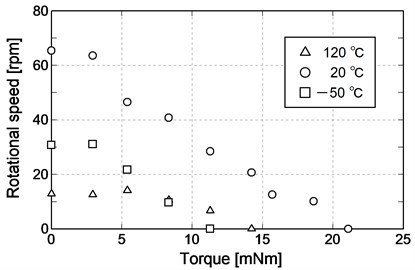
On the other hand, the characteristic of the torque-rotational speed fell in both of low temperature and high temperature compared with room temperature. The cause of the fall in low temperature environment by comparison with room temperature is considered according to the characteristic of the piezoelectric element and the freezing which occurs on the sliding surface. The causes of the fall in high temperature environment by comparison with room temperature are considered according to a decline of piezoelectric of the piezoelectric element and a decline of the hardness of the adhesive which attaches the piezoelectric element to the elastic body. The respective reasons were considered already at Section 4.2 and Section 4.3.
5. Conclusions
Development of the SUSM for space aiming at alternative use of the actuator used by an artificial satellite is being tried by this investigation. The SUSM for space has to be driven by both of high temperature environment and low temperature environment because an artificial satellite is exposed to high temperature environment and low temperature environment in space. The piezoelectric element and the adhesive of the SUSM were selected and estimated in high temperature environment by the previous investigation. So, it was the purpose of this investigation to estimate in low temperature environment to the piezoelectric element and the adhesive selected in high temperature environment. And it was also the purpose of this investigation to estimate the characteristic of the SUSM in low temperature environment and the temperature cycle.
When durability tests for the SUSM were carried out in temperature of −80 °C, approximately 60 minutes as accumulated drive time was achieved. Therefore, it was confirmed that the piezoelectric element and the adhesive selected in high temperature environment also function in low temperature environment. On the other hand, the characteristic of the SUSM was estimated in the environment of the temperature cycle. It was confirmed that piezoelectric of the piezoelectric element is maintained irrespective of the temperature from measuring result of impedance. The characteristic of the SUSM of high torque in low speed was confirmed in high temperature environment and low temperature environment. And the decline of the rotational speed was observed in high temperature environment and low temperature environment, but it was confirmed to return to the usual rotational speed again in room temperature.
References
-
Sashida T., Kenjo T. An Introduction to Ultrasonic Motors. Oxford University Press, Oxford, 1993.
-
Ferreira A., Minotti P. High-performance load-adaptive speed control for ultrasonic motors. Control Engineering Practice, Vol. 6, Issue 1, 1998, p. 1-13.
-
Morita T. Miniature piezoelectric motors. Sensors and Actuators A, Vol. 103, 2003, p. 291-300.
-
Mashimo T. Micro ultrasonic motor using a one cubic millimeter stator. Sensors and Actuators A: Physical, Vol. 213, 2014, p. 102-107.
-
Toyama S., Nishizawa U., Oohashi T. Intravascular stent motor powered by ultrasonic irradiation. Vibroengineering Procedia, Vol. 3, 2014, p. 346-350.
-
Toyama S., Sugitani S., Zhang G., Miyatani Y., Nakamura K. Multi degree of freedom spherical ultrasonic motor. Proceedings of IEEE International Conference on Robotics and Automation, 1995, p. 2935-2940.
-
Purwanto E., Toyama S. Control method of a spherical ultrasonic motor. Proceedings of IEEE/ASME International Conference on Advanced Intelligent Mechatronics, 2003, p. 1321-1326.
-
Takesue N., Ohara T., Ishibashi R., Toyama S., Hoshina M., Hirai Y., Fukaya N., Arata J., Fujimoto H. Position control methods of spherical ultrasonic motor. Proceedings of IEEE/RSJ International Conference on Intelligent Robots and Systems, 2010, p. 3061-3066.
-
Guo Z., Bai Y., Yi L., Guo J., Wang J. A novel method on real-time measurement of 2-DOF motions of spherical ultrasonic motor. Applied Mechanics and Materials, Vol. 416, Issue 417, 2013, p. 1080-1085.
-
Takemura K., Park S., Maeno T. Control of multi-dof ultrasonic actuator for dexterous surgical instrument. Journal of Sound and Vibration, Vol. 311, 2008, p. 652-666.
-
Fukaya N., Asfour T., Dillmann R., Toyama S. Development of a five-finger dexterous hand without feedback control: The TUAT/Karlsruhe humanoid hand. Proceedings of IEEE/RSJ International Conference on Intelligent Robots and Systems, 2013, p. 4533-4540.
-
Toyama S., Fukaya N. Development of spherical ultrasonic motor for critical environment. Vibroengineering Procedia, Vol. 1, 2013, p. 44-47.
-
Nishizawa U., Oohashi T., Toyama S. Evaluation of spherical ultrasonic motor for space in high temperature condition. Journal of Vibroengineering, Vol. 18, Issue 2, 2016, p. 916-926.
Cited by
About this article
This work was supported by JSPS KAKENHI Grant Number JP16K06060, and NSK-FAM.

