Abstract
This paper aims to present a proof-of-concept for a novel piezoelectric motor using a single-phase driving signal. The stator is constructed by bonding a Terfenol-D plate and a piezoelectric ceramic (PZT) plate onto the outer surface of a metal base. The PZT plate based on d31 effect is used to simultaneously excite two in-plane bending modes of the stator. Similarly, the Terfenol-D plate can also be used to excite the two bending modes. By superposition of the two bending modes, elliptical motions of the stator surface points are generated. The working modes and vibration characteristics of the motor are analyzed by finite element analysis software. The resonance frequencies of the two bending modes are tuned to be close by additional mass. The dimensions of the stator are optimized to maximize the output displacement. To confirm the feasibility of the proposed design, a prototype motor is fabricated and tested. The size of the prototype motor is about 11.2×10.7×28.0 mm3. The tested resonance frequencies of the two bending modes are 16.0820 kHz and 16.3476 kHz respectively. The maximum no-load speed is 85 rpm. The applied driving voltage is 100 Vo-p (peak voltage) at a frequency of 16.34 kHz.
1. Introduction
Piezoelectric motors have been developed over 30 years. Nowadays, all kinds of piezoelectric motors have been proposed and some of them have been widely used as a direct-drive module in micro-positioning mechanisms and medical instruments for their attractive properties [1-5], such as short time response, good micro-positioning capability, large holding force without power supply, etc. However, from the practical point of view, smaller and more compact piezoelectric motors are still in great demand in medical applications, optics and semiconductor industries [6-8].
Exploring new motor structures is an effective way to minimize the size of the motor. The typical design for piezoelectric motors is to use a rectangular plate actuator based on longitudinal and bending modes. In 1995, Nanomotion Company first developed a motor using a thin rectangular PZT plate [9]. Appropriate polarization division of the PZT plate was made to excite longitudinal and bending modes. In 2014, Wan and Hu [10] also proposed a motor using longitudinal and bending modes. The stator consisted of a metal plate and eight PZT patches. Later, Yang et al. [11] designed a bonded-type piezoelectric motor to realize the miniaturization. The dimensions of the motor are about 50×10×8 mm3. Aiming at compactness in size, motors using other vibration modes were also presented [12-14]. However, the above-mentioned motors are normally driven by two-phase signals and the driving circuit is complicated.
In this paper, to miniaturize the total system, a single-phase driving-type piezoelectric motor is reported. The d31 effect of the PZT plate is adopted to excite two in-plane bending modes of the stator. Desired elliptical movement is produced by superimposition of the two bending modes. Compared with the previous piezoelectric motor, the geometry of the stator is carefully designed to match the resonance frequencies of the two bending modes and then to maximize the output displacement. The Terfenol-D plate can be used to alter the resonance frequencies of the stator by applying an external DC magnetic field, which has been verified by reference [4] and is not discussed in this paper. The superiority of this design is due to its compactness and reduced number of structural elements.
As a fundamental work, this paper begins with the structure design of the motor, and then the actuation principle is illustrated. After that, the vibration characteristics of the motor including its natural frequencies, output displacements in frequency and time domain and trajectory of the driving point are all analyzed by using the finite element (FE) analysis to explain why the proposed motor can be driven by a single-phase signal. Finally, a prototype motor is fabricated. Through some fundamental experiments, the characteristics of the motor are evaluated.
2. Structure and working principle
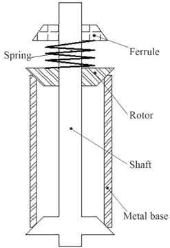
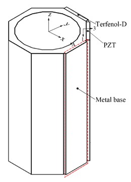
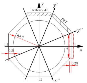
The single-phase drive motor consists of a rotor, a stator and the preload mechanism, as shown in Fig. 1(a). The stator is formed by bonding a Terfenol-D plate and a PZT plate onto the outer surface of a metal base using epoxy resin adhesive (Fig. 1(b)). The metal base is a metallic tube whose external wall is grounded into eight planes forming an octagon. The added mass on the right side of the metal base denoted by red-dotted lines in Fig. 1 is used to tune the resonance frequencies and vibration directions of the stator. The adjustment mechanism is specifically discussed in Section 3. The rotor is pressed against the stator by a spring and a ferrule. The PZT plate is polarized in the thickness direction (the 3 direction in Fig. 1(b)). The Terfenol-D plate is magnetized along the z direction.
Fig. 1Structure of the motor: a) configuration of the motor; b) three-dimensional stator model; c) main dimensions of the metal base (mm)
a)
b)
c)
For the PZT plate, the relationship between the strain and electric field intensity can be expressed as follows:
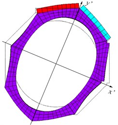
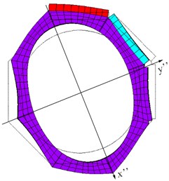
where ε1 is the strain of PZT plate in the length direction (the 1 direction in Fig. 1(b)), L is the length of the PZT plate, ΔL is the deformation along the length direction, and Ε3 is the electric field intensity applied parallel to the polarization direction. The deformation of the PZT plate ΔL is used to excite the two working modes of the stator, which are shown in Fig. 2.
When the Mode A is excited, the stator stretches along the y' direction and concurrently contracts along the x' direction. When the Mode B is excited, the stator expands toward the x'' direction, which indicates the stator shrinks in the y'' direction. The included angle between the vibration directions (y' and y'') is 45 degrees. Because the PZT plate is oriented by 67.5 degrees to the directions of minimum and maximum bending moment of inertia (y' and y''), theoretically speaking, the deformation of the PZT plate can be used to excite the two bending modes. When an AC voltage with a frequency between the two resonance frequencies is applied to the PZT plate, the bending modes will respond asynchronously with a phase difference due to the structural damping of the stator. Making use of the two bending modes can generate elliptical locus on the stator surface.
Similarly, because the Terfenol-D plate is oriented by 67.5 degrees to the extension directions of the two bending modes (y' and x''), the Terfenol-D plate can also be used to excite the two modes. Thus, the motor can be driven with an external AC magnetic field applied on Terfenol-D plate or electric field applied on PZT plate. In this paper, we mainly analyze the electrically actuated characteristic of the motor.
Fig. 2Two in-plane bending modes: a) mode A; b) mode B
a)
b)
3. Vibration characteristics simulation
In order to understand the dynamic behavior of the stator, the FE software, ANSYS, is employed. The coupled-field analysis in ANSYS enables us to perform modal, harmonic and transient analyses of the prototype motor. To build the FE model, the PZT plate is meshed using the 3D coupled-field solid element SOLID5. The SOLID5 element has eight nodes with up to six degrees of freedom at each node. The metal base and Terfenol-D plate are meshed with SOLID73, the 3D solid element defined by eight nodes.
Modal analysis was first carried out to analyze the vibration modes of the stator. The split of the two mode frequencies is due to different stiffness of the PZT plate and Terfenol-D plate. Therefore, the structural parameters of the stator should be adjusted until the resonance frequencies of the two bending modes are close. In order to excite the two bending modes using the d31 inverse piezoelectric effect of the PZT layer, the vibration directions of the two bending modes should also be adjusted. The optimal vibration directions are the y' direction (67.5 degrees) and the y'' direction (22.5 degrees), as indicated in Fig. 1(c). However, because the stiffness of PZT and Terfenol-D is different, the stator is asymmetric with respect to the y' direction, which results in the vibration directions of the Mode A and Mode B deviating from the y' and y'' directions, respectively.
In order to adjust the resonance frequencies and the vibration directions of the two bending modes, an additional mass is attached to the right side of the regular octagon. The added mass is indicated by red-dotted lines in Fig. 1. Adding mass at positions I is able to change the resonance frequencies and vibration directions of the two bending modes. The optimization program based on APDL is used to optimize the stator structure. The final dimensions of the stator are shown in Fig. 1(c). Furthermore, the height of the stator is 20 mm. The dimensions of the PZT plate and Terfenol-D plate are both 4.3×0.5×20 mm3. The size of the added mass is 4×0.28×20 mm3. Table 1 lists the material properties used in simulation model. Phosphor bronze is chosen for the metal body. Piezoelectric element used in the motor is PZT-8.
Table 1Material constants
Material | PZT-8 | Phosphor bronze | Terfenol-D |
Density (kg/m3) | 7500 | 8900 | 9250 |
Elastic modulus (×1010 N/m2) | (13.97.787.4300013.97.4300011.50002.56003.0602.56) | 11.7 | 4 |
Poisson’s ratio | 0.31 | 0.3 | 0.3 |
Piezoelectric constant (C/m2) | (00-1.2300-1.23002.8904.9604.9600000) |
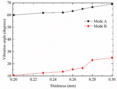
Fig. 3 shows the relationship between the thickness of the added mass and the resonance frequencies of the stator. Fig. 4 indicates the plot of the vibration directions of two working modes versus the thickness of the added mass. The thickness of the added mass is chosen as a variable. The optimal resonance frequencies of the two working modes are 18.411 kHz and 18.412 kHz, respectively. The difference between the two mode frequencies is 0.001 kHz.
Fig. 3Resonance frequencies of the two bending modes under added mass
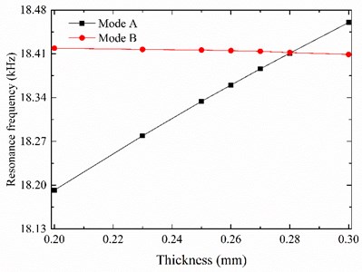
Fig. 4Vibration directions of the two bending modes under added mass
From Fig. 3, it can be recognized that increasing the added mass causes the resonance frequency of Mode B to decrease slightly. However, the resonance frequency of Mode A is directly proportional to the added mass. This is mainly due to different effects of adding mass on resonance frequencies of the two bending modes. Similarly, adding mass at the symmetrical position of I (II and III) indicated in Fig. 1(c) has the same influence on the resonance frequencies of the two bending modes.
Fig. 4 indicate that the vibration directions of the Mode A and Mode B can be adjusted to the best position by adding mass. Besides, the resonance frequencies and the vibration directions of the stator simultaneously reach the optimum.
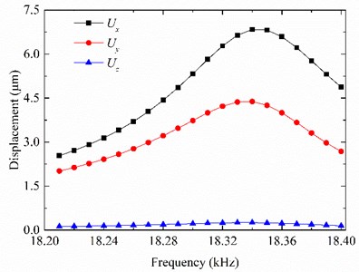
Harmonic analysis was subsequently conducted to obtain the dynamic characteristics of the motor in frequency domain. The peak amplitude of the input voltage was set to be 100 V. Fig. 5 shows the output displacements of point A (Fig. 1(b)). As indicated in Fig. 5, the resonance frequencies obtained from modal analysis and harmonic analysis almost coincide. The slight difference is attributed to the fact that in modal analysis external electrical excitation is not considered. The maximum amplitude of Ux is 6.8 μm. The maximum amplitude of Uy is 4.4 μm. Moreover, the amplitudes of Ux and Uy are more than 10 times larger than that of Uz as the desired vibrations are in the x-y plane.
Fig. 5Output displacements of the driving point A in frequency domain
Transient analysis was also carried out to determine the dynamic response of the motor under the action of time dependent load. In the transient analysis, the amplitude of the excitation voltage was set to be 100 V. The exciting frequency was 18.3 kHz. Each excitation cycle was discretized by 40 data points. The time step was determined from the excitation frequency. The damping ratio was set at 3 %.
Fig. 6Output displacements of the driving point A at steady state
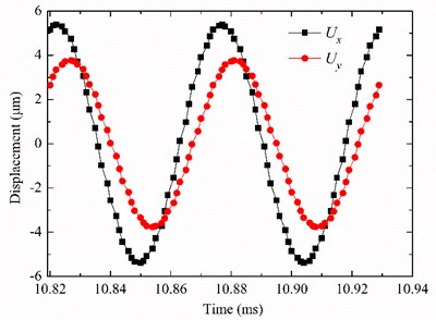
Fig. 7Elliptical trajectory of the driving point A at different exciting frequencies
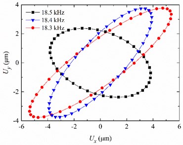
Fig. 6 shows the output displacements Ux and Uy of the point A at steady state. The phase difference between Ux and Uy is about 27 degrees. The maximum vibration amplitudes of the driving point A are 5.4 μm and 3.8 μm respectively in the x and y directions. Moreover, the phase difference between the output displacements Ux and Uy can be adjusted by altering the frequency of the applied AC voltage. When the excitation frequency is 18.5 kHz, the phase difference between output displacements Ux and Uy is 108 degrees. For the motor, the output displacement Ux of driving point A serves to intermittently press the rotor to the stator. The output displacement Uy of point A serves to move the rotor by the frictional force. Consequently, the driving point moves with elliptical trace, as illustrated in Fig. 7. It can be seen that the motion trajectories of the point are varied at different driving frequencies.
4. Experiments
Based on the simulation results, a prototype motor was fabricated. The weight of the prototype motor is 9 g, and the weight of the stator is 7 g. The prototype motor is measured at 11.2×10.7×28.0 mm3.
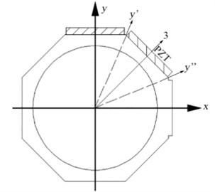
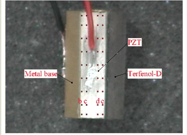
A scanning laser Doppler vibrometer (Polytec PSV-300F) was used to measure the vibration characteristics of the fabricated stator. The Mode A and Mode B of the stator can be simultaneously excited when the metal base is grounded, the outer surface electrode of the PZT plate is connected to an excitation voltage. The excited vibrations of the stator in the y' and y'' directions both have vibration components in the direction perpendicular to the PZT plate (the 3 direction as shown in Fig. 8(a). It is the physical basis for using a scanning laser Doppler vibrometer to simultaneously test the resonance frequencies of the Mode A and Mode B. Therefore, the surface of the stator to which the PZT plate is bonded is taken as the test region for the Mode A and Mode B test. The measuring point is shown in Fig. 8(b).
Fig. 9 shows the measured vibration characteristics of the stator. It is found that the resonance frequencies of the in-plane bending modes are 16.0820 kHz and 16.3476 kHz respectively, which are different from the results obtained by the FE analysis. This difference may have been caused by inaccuracy in the materials’ physical parameters assigned to the FE model and machining geometric errors. The frequency difference of the two working modes is 0.2656 kHz. The magnitudes of the two vibration modes are different because the chosen measuring point is not at the center line of the test region.
Fig. 8Vibration test of the stator: a) measuring principle; b) the test region
a)
b)
Additionally, the deformation of the stator was measured to assess the mode shape. A sinusoidal voltage with an amplitude of 100 V was applied to the PZT plate for the following measurements. The detection points (b, c, d and e) on the test surface are shown in Fig. 8(b). When the excitation frequency is 16.0820 kHz, the vibration amplitude of each detection point is shown in Table 2. It can be seen that the oscillation displacements of the selected points are different. The displacements of the points (b to e) increase linearly. The point e closest to the Terfenol-D plate has the largest displacement. Therefore, the mode shape at the resonance frequency of 16.0820 kHz is confirmed as being similar to the Mode A. Then, the resonance frequency of Mode B is 16.3476 kHz.
Table 2Measured displacements of the detection points
Frequency (kHz) | Detection point | Displacement direction | Magnitude (μm) |
16.0820 | b | 3 | 2.68 |
c | 3 | 4.03 | |
d | 3 | 5.11 | |
e | 3 | 6.32 |
Fig. 10 presents the experimental setup used to drive the piezoelectric motor. The voltage, which is supplied to the piezoelectric element of the stator, is produced by a function generator (GWINSTEK SFG-2110) and then amplified by power amplifier (HFVA-42). The frequency and amplitude of the actuation voltage can be adjusted by using the function generator and power amplifier.
Fig. 9Vibration scanning results of the prototype motor
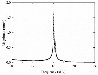
Fig. 10Experimental setup for evaluation of the piezoelectric motor
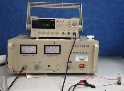
Fig. 11Plot of the speed versus the exciting frequency
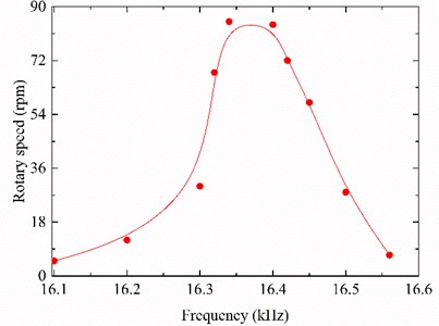
Fig. 11 displays the plot of the rotary speed versus the frequency of the single-phase exciting voltage. The amplitude of the actuation voltage is 100 V as in the FE analysis. The prototype motor achieves a maximum rotary speed of 85 rpm as the exciting frequency is 16.34 kHz. Besides, the motor speed is almost linearly related with the exciting frequency in the range of 16.40-16.56 kHz. Hence, the speed adjustment is feasible by changing the exciting frequency. Variation of the resonance frequency caused by external conditions (temperature, pre-stress or load) can be adjusted by applying external magnetic field.
5. 5. Conclusions
A piezoelectric motor driven by a single-phase signal has been successfully realized. The PZT plate is used to excite two in-plane vibration modes of the stator. The two mode frequencies split because of stator symmetry breaking. In addition, the vibration directions of the Mode A and Mode B deviate from the y' and y'' directions, respectively. In this paper, the resonance frequencies and vibration directions of the two modes are adjusted by adding additional mass to an octagon, which is beneficial to maximize the output displacement of the stator. Combined bending modes are excited by applying an AC voltage with a frequency between the two resonance frequencies. Then a travelling wave is generated and the rotor is driven to rotate by the travelling wave in the stator.
By using FE software, the final structural parameters of the stator and the output displacements of the driving point on the stator surface are obtained. The results indicate that the proposed motor can be driven by a single-phase signal. Based on the simulation results, a prototype motor is fabricated and tested. The no-load speed reaches 85 rpm at a frequency of 16.34 kHz. The applied AC voltage is 100 Vo-p. As the two working modes of the stator are in the x-y plane, the resonance frequencies are not influenced by the height of the stator. Therefore, the overall size of the motor can be further reduced. The motor overcomes the shortcomings of complex structure and difficult fabrication in normal piezoelectric motors.
References
-
Shi Y. L., Zhao C. S. A new standing-wave-type linear ultrasonic motor based on in-plane modes. Ultrasonics, Vol. 51, Issue 4, 2011, p. 397-404.
-
Chang L. K., Tsai M. C. Design of single-phase driven screw-thread-type ultrasonic motor. Review of Scientific Instruments, Vol. 87, Issue 5, 2016, p. 055002.
-
Chen Z. Z., Chen Y., Zhou T. Y., et al. A Nut-Type Ultrasonic Motor Driven with Single Phase Signal. Vibration Engineering and Technology of Machinery. Springer International Publishing, 2015, p. 835-843.
-
Zhai J. Y., Dong S. X., Xing Z. P., et al. Tunable magnetoelectric resonance devices. Journal of Physics D: Applied Physics, Vol. 42, Issue 12, 2009, p. 122001.
-
Ho S. T., Jan S. J. A piezoelectric motor for precision positioning applications. Precision Engineering, Vol. 43, 2016, p. 285-293.
-
Tamura H., Shibata K., Aoyagi M., et al. Single phase drive ultrasonic motor using LiNbO3 rectangular vibrator. Japanese Journal of Applied Physics, Vol. 47, 2008, p. 5-4015.
-
Yokoyama K., Tamura H., Masuda K., et al. Single-phase drive ultrasonic linear motor using a linked twin square plate vibrator. Japanese Journal of Applied Physics, Vol. 52, Issue 7, 2013, p 07HE03.
-
Hsiao S. W., Tsai M. C. Single-phase drive linear ultrasonic motor with perpendicular electrode vibrator. Japanese Journal of Applied Physics, Vol. 49, Issue 2, 2010, p. 024201.
-
Zumeris J. Ceramic Motor. U.S. Patent 5453653, 1995.
-
Wan Z. J., Hu H. Modeling and experimental analysis of the linear ultrasonic motor with in-plane bending and longitudinal mode. Ultrasonics, Vol. 54, Issue 3, 2014, p. 921-928.
-
Yang X. H., Liu Y. X., Chen W. S., et al. Miniaturization of a longitudinal-bending hybrid linear ultrasonic motor. Ceramics International, Vol. 41, 2015, p. 607-611.
-
Li C., Lu C. Y., Ma Y. X., et al. Design of an ultrasonic motor with multi-vibrators. Journal of Zhejiang University – Science A, Vol. 17, Issue 9, 2016, p. 724-732.
-
Cagatay S., Koc B., Uchino K. A 1.6 mm, metal tube ultrasonic motor. IEEE Transactions on Ultrasonics, Ferroelectrics, and Frequency Control, 2003, 50(7): 782-786.
-
Zhao C. S. Ultrasonic Motors: Technologies and Applications. Springer Science and Business Media, 2011.
Cited by
About this article
This project is supported by the National Natural Science Foundation of China (No. 11174206 and No. 61471237), the Open Fund of State Key Laboratory of Ocean Engineering (No. 0507), and the SAST Fund (No. 201347).

