Abstract
Structural Health Monitoring (SHM) and impact monitoring of composite structures have become important research topics in the recent year. In this research, a non-destructive vibration-based damage detection method is formulated using Genetic Algorithm (GA) and compared with classical method. The robustness and reliability of the capability to locate and to estimate the severity of damage, based on changes in dynamic characteristics of a structure, is investigated. The objective function for the damage identification problem is established by using the residual force method (FRM). Numerical experiments using finite element analysis are performed on composite beams with different damage scenarios in order to clarify the validity of the developed technique. The comparison between estimated and real damage illustrates the efficiency of the algorithm in damage detection. The results show that the present approach is correct and efficient for detecting structural local damages in composite beam structures.
1. Introduction
The non-destructive testing evaluation and condition assessment of aging infrastructure and mechanical engineering have become important research topics and received much attention for structural damage detection. There is always a need to develop and implement accurate methods of damage detection in structures using intelligent artificial methods. The frequencies and mode shapes are the most popular modal parameters used in the damage detection techniques in recent years [1-6]. The basic idea of these techniques is that the change in modal parameters can be used to detect the damage in a structure. If damage exists in a structure, an unbalance error resulting from the substitution of a refined finite element model and the measured modal data into the structure eigenvalue equation, which is called the residual modal force, takes place. This residual modal force can be used as an indicator of damage detection. In this paper, to quantitatively identify the extent and location of the damage, we used the residual modal force as an objective function.
Damage detection and localization in thin plates based on vibration analysis using BAT algorithm in beam like and complex structures by Khatir et al. [7]. Sheinman [8] proposed a modified residual force vector to detect damage in beam-like structures. The identification of damage was formulated as an optimization problem using three objective functions; a) the change of natural frequencies, b) Modal Assurance Criterion (MAC) and c) Modal Assurance Criterion natural frequency. As introduced in [9], the residual forces were used to detect damage in beam and truss structures based on mass and stiffness matrices. The Coordinate Modal Assurance Criterion (COMAC), which made use of the numerical and experimental vibration modes, was used to determine the magnitude and position of damage by Iturrioz, et al. [10]. The application of the change in modal curvatures to detect damage in the concrete bridge was introduced by Wahab and De Roeck [11]. The application of ultrasonic guided waves generated by piezoelectric smart transducers has become one of the widely-used techniques in structural health monitoring. In references [12, 13], the authors used this concept for damage identification in a shear structure and a tapered and non homogeneous beam using all mode shapes that were considered in the objective function formulation. In reference [4], the authors presented a new approach of inverse damage detection and localization based on model reduction. The problem was formulated as an inverse problem, where an optimization algorithm was used to minimize the cost function expressed as the normalized difference between a frequency vector of the tested structure and its numerical model. The damage indicator based on vibration data are used to detect and locate defects in stratified beam structures [14]. A novel wave number analysis approaches were developed and discussed to show how they could be used to investigate Lamb wave interactions with delaminated plies [15].
The residual force method is effective in damage localization using modal data [16]. The authors of reference [16] used residual modal force vectors for damage localization. The quantitative of multidamage monitoring method for large-scale complex composite was presented in [17]. In reference [18], the authors proposed a new approach to capture and process the full matrix of all transmit-receive time-domain signals from the array. The damage localization approach based on the residual forces method to locate damage. The subspace rotation damage identification algorithm was introduced by Kahl, and Sirkis [19] using residual forces. The residual force vector was used in many methods in the literature or detecting and locating damage in structures [20, 21].
In the present paper, in the first section, we develop a damage indicator residual force coupled with FEM. In the second section, we quantify damage using FEM coupled with optimization method, i.e. GA. The residual modal force is used as an objective function to compare the measured data with the ones calculated by GA.
2. The residual forces method
Testing structural damage detection and localization methods based on the residual force vector [22] is studied in this paper. The damage index of the jth element is expressed as the change of the rigidity of a finite element, i.e.:
where and are the th element of the elementary matrix of the damaged and undamaged structure, respectively. In Eq. (1), represents the variation of stiffness, is in the interval and indicates a loss of rigidity of thelement, i.e. 0 for undamaged and 1 for damaged element. We consider that the mass matrix of the damaged structure is not affected by damage, and rigidity matrix of the damaged element change as given below:
where . The modal residual force vector can be written as:
Eq. (4) can be written in a matrix form as:
where the coefficient of the matrix is:
where is the actually th mode node force vector of the th element in globe coordinates.
The modal residual force vector can be written as:
Eq. (5) can be rewritten as:
where is the number of modes, while is the number of elements. The solution of the system of equations in Eq. (8) allows us to determine the values of the damage indicators:
3. Finite element method
We consider in this article, a unidirectional composite beam. We model the structure using SI12 finite elements [23]. Each node of a finite element has three degrees of freedom, i.e. displacement normal to the beam, longitudinal displacement and rotation around the -axis, as shown in Fig. 1. Therefore, the total number of degrees of freedom of the finite element SI12 is 12.
Fig. 1Unidirectional CFRP [18]
![Unidirectional CFRP [18]](https://static-01.extrica.com/articles/18302/18302-img1.jpg)
![Unidirectional CFRP [18]](https://static-01.extrica.com/articles/18302/18302-img2.jpg)
The coefficients of stiffness of the beam using the stiffness are given by the following relationships:
where : Shear correction factor, : width of beam and is bottom coordinate of the th layer:
where : Young’s modulus of the th layer in the direction, : transverse shear modulus of the th layer.
The generalized mass densities , and are given by the following equations:
where : width of the beam, : coordinate of the th layer.
The elementary stiffness matrix can be written as:
With:
The elementary mass matrix is defined by the following relationship:
where is the matrix of shape functions and is the generalized matrix densities. The material properties and beam dimensions of CFRP (Carbon Fiber Reinforced Polymer) composite beam [18] are given in Table 1. In this paper, we proposed several damage scenarios as summarized in Table 2, in which damaged element(s) and damage rate are given for each damage scenario.
Table 1Material properties and beam dimensions
Ply property | Mean value |
Length (mm) | 200 |
Width (mm) | 20.253 |
Thickness (mm) | 1.7 |
Young modulus (N/mm2) | 133000 |
Density (Ns2/mm4) | 1.37610-9 |
Table 2Damage scenarios for numerical simulations
Damaged Element(s) | Damage rate % | |
Scenario 1 | 3 | 25% |
Scenario 2 | 8 | 50 % |
Scenario 3 | 3 and 8 | 25 % |
Scenario 4 | 2, 4, 6 and 8 | 10, 20, 30 et 40 % |
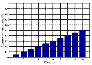
Scenario 5 | Uniform damage | 5, 10,15, 20, 25, 30, 35, 40, 45, 50 |
4. Evaluation of damage indicators
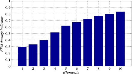
The natural frequencies of the undamaged and damaged structures for all damage scenarios are shown in Table 3. Values of the damage indicator , for damage scenarios 1 to 5, are shown and plotted in Figs. 2 to 6, respectively. For damage scenarions 1 and 2, it can be seen from Figs. 2 and 3 that the value of the indicator is significant for the damaged element and therefore this method allowed us to detect and localized the damage for a single damage scenario. For the multiple damage scenarios, Figs. 4 to 6, it can be seen that the damage elements are correctly identified using the damage indicator. Therefore, this technique is also suitable for multiple damage cases.
Table 3Natural frequencies (Hz) of the undamaged and damaged beam structures
Mode 1 | Mode 2 | Mode 3 | Mode 4 | Mode 5 | |
Undamaged beam CFRP [24] | 67.49 | 423.00 | 1184.53 | 2321.23 | – |
Undamaged beam – FEM | 67.50 | 422.80 | 1183.50 | 2318.60 | 3833.60 |
Damage scenario 1 | 65.60 | 422.00 | 1159.80 | 2271.10 | 3806.50 |
Damage scenario 2 | 67.40 | 408.20 | 1082.40 | 2177.30 | 3749.70 |
Damage scenario 3 | 65.60 | 417.10 | 1124.20 | 2211.10 | 3773.60 |
Damage scenario 4 | 65.20 | 392.90 | 1086.80 | 2131.00 | 3627.30 |
Damage scenario 5 | 62.90 | 367.80 | 1006.80 | 1960.80 | 3234.50 |
5. Genetic algorithm (GA)
In this section, we present the optimization method, Genetic Algorithm (GA), which will be used along with the residual forces to quantify damage. The genetic algorithm used in this paper is the Standard genetic algorithm, which is based on Binary Encoding. The residual forces are used in the objective function to compare the data between measured and calculated by GA.
Fig. 2Damage indicators for damage scenario 1 αM=0.05460.05960.30560.08050.04740.03370.02750.02380.02080.0180
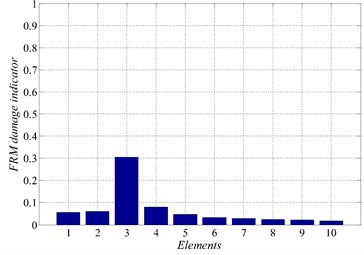
Fig. 3Damage indicators for damage scenario 2 αM=0.05070.05460.06660.09320.13480.18080.22490.62680.22770.1953
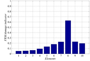
Fig. 4Damage indicators for damage scenario 3 αM=0.07140.07750.32020.11320.09340.09070.09560.31850.07980.0690
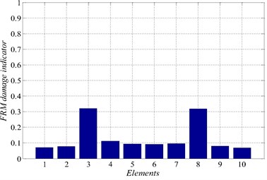
Fig. 5Damage indicators for damage scenario 4 αM=0.10760.19370.13250.34190.2220.46450.26050.55490.22860.1974
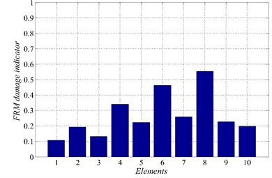
Fig. 6Damage indicators for damage scenario 5 αM=0.29390.33270.39840.51600.61930.67420.71360.76890.79760.8364
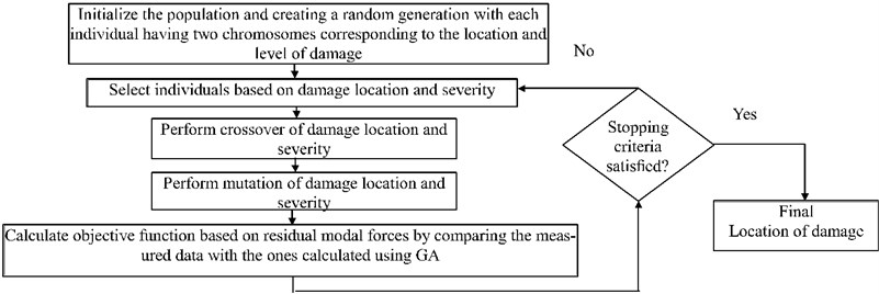
Genetic Algorithm is a global probabilistic search algorithm inspired by Darwin’s survival-of-the fittest theory originally developed by Holland [25-27] combines algorithms to solve optimization problems using the principles of evolution. In this optimization method, information about a problem posed, such as variable parameters, is coded into a genetic string known as an individual (chromosome). In this study, we have two chromosomes that represent damage location and severity. Each of these individuals has an associated fitness value, which is usually determined by the objective function using data of residual forces to be minimized. This optimization method has been shown to be able to solve the optimization problem through mutation, crossover and selection operation applied to individuals in the population. All numerical studies presented in this paper are implementing in MATLAB. In applying GA, the following steps are programmed:
1) Initializing population of individuals, created in real encoding as a random generation. Each individual has two chromosomes corresponding to the location and level of damage.
2) Evaluating each individual by introducing the proposed parameters (damage element and level) into FEM using genetic algorithm.
3) Evaluating populations according to their fitness value and then ranking them. A proportion for breeding a new generation will be selected.
4) Selecting the best populations.
5) Crossover of individuals to produce the population of the next generation.
6) Mutation of a specified level of the resulting population.
7) Replacing of the old population by new one and coming back to the step 2.
Flowchart of a basic genetic algorithm is given in Fig. 1.
Through series of identification tests, the following genetic parameters were chosen based on the accuracy of results: The number of generation used between (50-300) depend number of damaged element, population size = 300, crossover rate = 0.8 i.e. 800 individuals were selected for crossover, the mutation rate = 0.01. The mutation was used to avoid the convergence of the solution toward local optimums by creating diversity.
Fig. 7Flowchart of a genetic algorithm
5.1. Results and discussion
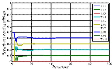
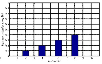
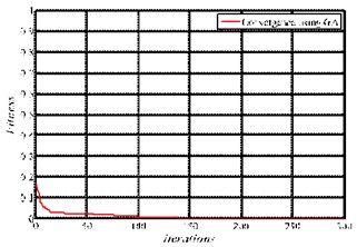
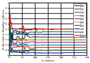
In case of using GA, the residual force method (FRM) is used as an objective function combined with finite element models. The same damage scenarios as presented in Table 2 are used herein. The results are shown in Figs. 8 to 12, in which three plotted for each damage scenario are presented; a) Fitness b) Damage indicator c) Convergence of damaged elements. For the single damage scenario, D1 and D2, it can be seen, in Figs. 8 and 9, that the algorithm is converged after few iterations, i.e. before reaching 10 iterations, and the damage location and severity are correctly identified with higher precision.
Fig. 8Convergence and damage identification for damage scenario 1
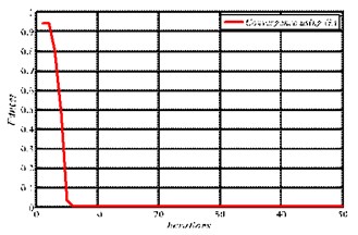
a) Fitness convergence
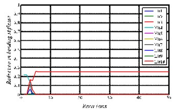
b) Convergence of damaged elements
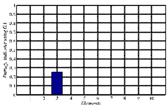
c) Damage identification
Fig. 9Convergence and damage identification for damage scenario 2
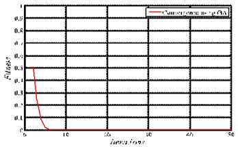
a) Fitness convergence
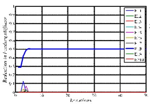
b) Convergence of damaged elements
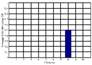
c) Damage identification
Similarly, for multiple damage scenarios, scenarios D3 to D5, in Figs. 10 to12, all damage locations and severities are correctly found. However, as the number of damage elements increases, the number of iterations increases and the convergence becomes slower. In general, we conclude that the results show that GA algorithm is able to quantify damage in most scenarios using data of residual force method within the first few iterations with high accuracy. However, for damage scenario D5, more than 130 iterations are required in order to reach convergence, as it can be seen in Fig. 12.
Fig. 10Convergence and damage identification for damage scenario 3
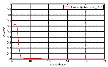
a) Fitness convergence
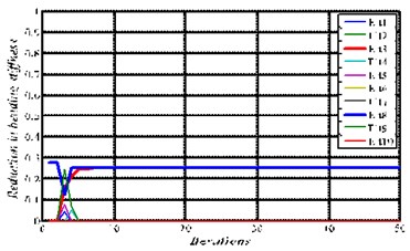
b) Convergence of damaged elements
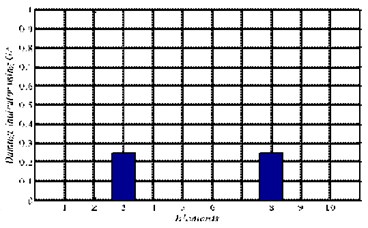
c) Damage identification
Fig. 11Convergence and damage identification for damage scenario 4
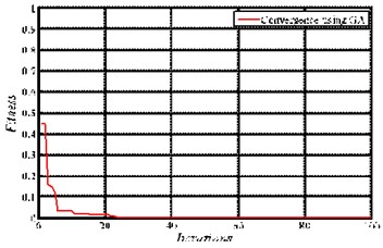
a) Fitness convergence
b) Convergence of damaged elements
c) Damage identification
Fig. 12Convergence and damage identification for damage scenario 5
a) Fitness convergence
b) Convergence of damaged elements
c) Damage identification
6. Conclusion
In this article, a method for inverse problem is proposed for damage detection and severity in CFRP composite beam structures. The proposed technique is based on Genetic Algorithm (GA), residual force method (RFM) and finite element method (FEM). The objective function is based on using the calculated data of residual forces and compare them to the measured ones using GA. Numerical experiments using FEM are performed on composite beams with different damage scenarios in order to clarify the validity of the developed technique. The comparison between estimated and real damage illustrates the efficiency of the algorithm in damage detection. The results show that the present approach is correct and efficient for detecting structural local damages in case of single and multiple damage scenarios.
References
-
Zhou Y.-L., et al. Structural damage detection using transmissibility together with hierarchical clustering analysis and similarity measure. Structural Health Monitoring, 2016, https://doi.org/10.1177/1475921716680849.
-
Zhou Y.-L., Maia N., Wahab M. Abdel Damage detection using transmissibility compressed by principal component analysis enhanced with distance measure. Journal of Vibration and Control, 2016, https://doi.org/10.1177/1077546316674544.
-
Gillich G.-R., et al. Free vibration of a perfectly clamped-free beam with stepwise eccentric distributed masses. Shock and Vibration, 2016, https://doi.org/10.1155/2016/2086274.
-
Khatir S., et al. Damage detection and localization in composite beam structures based on vibration analysis. Mechanika, Vol. 21, Issue 6, 2015, p. 472-479.
-
Zhou Y.-L., Wahab Abdel M. Cosine based and extended transmissibility damage indicators for structural damage detection. Engineering Structures, Vol. 141, 2017, p. 175-183.
-
Gillich G. R., et al. Localization of transversal cracks in sandwich beams and evaluation of their severity. Shock and Vibration, 2014, https://doi.org/10.1155/2014/607125.
-
Khatir S., et al. Numerical study for single and multiple damage detection and localization in beam-like structures using BAT algorithm. Journal of Vibroengineering, Vol. 18, Issue 1, 2016, p. 202-213.
-
Sheinman I. Damage detection and updating of stiffness and mass matrices using mode data. Computers and Structures, Vol. 59, Issue 1, 1996, p. 149-156.
-
Baruh H., Ratan S. Damage detection in flexible structures. Journal of Sound and Vibration, Vol. 166, Issue 1, 1993, p. 21-30.
-
Iturrioz I., et al. Evaluation of structural damage through changes in dynamic properties. International Symposium on Nondestructive Testing Contribution to the Infrastructure Safety Systems in the 21st Century, 1999.
-
Wahab M. A., Roeck G. De Damage detection in bridges using modal curvatures: application to a real damage scenario. Journal of Sound and Vibration, Vol. 226, Issue 2, 1999, p. 217-235.
-
Panigrahia S. S., Chakravertyb, Mishrac B. Damage assessment of a non-homogeneous uniform strength beam using genetic algorithm. Proceedings of the 3rd IASTED African Conference, 2010.
-
Panigrahi S., Chakrayerty S., Mlshra B. Application of genetic algorithm for damage identification of non-homogenous tapered beam. Computer Methods in Materials Science, Vol. 8, Issue 2, 2008, p. 93-102.
-
Behtani A., Bouazzouni A. Localisation de défauts dans les structures poutres stratifiées basée sur des données modales. 20ème Congrès Français de Mécanique, Besançon, France, 2011, (in French).
-
Tian Z., Yu L., Leckey C. Delamination detection and quantification on laminated composite structures with Lamb waves and wavenumber analysis. Journal of Intelligent Material Systems and Structures, Vol. 26, Issue 13, 2015, p. 1723-1738.
-
Ricles J., Kosmatka J. Damage detection in elastic structures using vibratory residual forces and weighted sensitivity. AIAA Journal, Vol. 30, Issue 9, 1992, p. 2310-2316.
-
Qiu L., et al. A quantitative multidamage monitoring method for large-scale complex composite. Structural Health Monitoring, Vol. 12, Issue 3, 2013, p. 183-196.
-
Holmes C., Drinkwater B. W., Wilcox P. D. Advanced post-processing for scanned ultrasonic arrays: Application to defect detection and classification in non-destructive evaluation. Ultrasonics, Vol. 48, Issue 6, 2008, p. 636-642.
-
Kahl K., Sirkis J. Damage detection in beam structures using subspace rotation algorithm with strain data. AIAA Journal, Vol. 34, Issue 12, 1996, p. 2609-2614.
-
Ren W. X., Yu D. J., Shen J. Y. Structural damage identification using residual modal forces. Proceedings of 21st International Modal Analysis Conference, Florida, 2003.
-
Chiang D.-Y., Lai W.-Y. Structural damage detection using the simulated evolution method. AIAA Journal, Vol. 37, Issue 10, 1999, p. 1331-1333.
-
Shen J. Y., Sharpe Jr L. Damage detection using residual modal forces and modal sensitivity. Proceeding of 14th ASCE Engineering Mechanics Conference, 2000.
-
Rikards R. Analysis of Laminated Structures: Course of Lectures. Riga Technical University, Riga, 1991.
-
Capozucca R. Vibration of CFRP cantilever beam with damage. Composite Structures, Vol. 116, 2014, p. 211-222.
-
Holland J. Adaption in Natural and Artificial Systems. Ann Arbor MI: The University of Michigan Press, 1975.
-
Goldberg D. E., Holland J. H. Genetic algorithms and machine learning. Machine Learning, Vol. 3, Issue 2, 1988, p. 95-99.
-
Mitchell M., Holland J. H., Forrest S. When will a genetic algorithm outperform hill climbing? Ann Arbor, Vol. 1001, 1993, p. 48109.
Cited by
About this article
A. Behtani has carried out the research work related to the residual forces and has written large part of the manuscript. A. Bouazzouni has supervised the first author for the research on residual forces method. S. Khatir has carried out the finite element analysis and the genetic algorithm optimization, and has written part of the manuscript. S. Tiachacht has contributed in the implementation of the genetic algorithm method. Y.-L. Zhou has supervised S. Khatir for the implementation of the finite element analysis. M. Abdel Wahab has supervised all the work, contributed in the research concept and revised the manuscript.

