Abstract
To find out the effect of eccentricity of a gear wheel on inherent characteristics of a gear-rotor system, this paper establishes a pair of general transverse-rotational-axial-swinging multi degrees of freedom coupling helical gear meshing dynamic model based on the finite element method (FEM). Considering the influence of the azimuth, the meshing angle, the helix angle and the rotation direction of driving shaft on mesh stiffness matrix, it analyzes the effect of mesh stiffness and mesh damping on the inherent characteristics and the transient response of the system. It obtains the displacement response curve and the dynamic meshing force curve of all nodes responding to the incentives of static transmission error and unbalance while considering mesh damping. It concludes that the effects of gear coupling and eccentricity of gear wheel should be taken into account in a multi-parallel-shaft gear meshing rotor system.
1. Introduction
For its high efficiency and reliable kinematic accuracy, gear transmission is used as one of the most common mechanical transmission types and has been widely adopted in many industrial fields. For instance, generator set, gas turbine set, nuclear power equipment and aerospace etc. Working condition of a gear transmission system is very complex since it is usually affected not only by the internal incentives like time-varying gear mesh stiffness, static transmission error (STE), dynamic transmission error (DTE), backlash, but also by the external incentives like floating driving and resistance moment of the engine and nonlinear oil-film force of the bearings. Therefore, research on dynamic analysis of a gear system can reveal the inner mechanism that causes a gear vibration and the controlling of vibration can make stable, high-speed, and accurate transmission possible. With regard to unbalance, it almost exists in every rotor system and should be controlled strictly for its leading to inaccuracy and uncontrollability.
In recent years, many scholars have studied the gear transmission system based on different excitation types. For the single pair of gear meshing, references [1-3] developed dynamic models based on gear backlash, tooth modification and gear mesh impact respectively and dynamic analysis approved the validity of the method put forward. Skrickij et al established a mathematical transmission model of single gear meshing of an asynchronous motor, and analyzed effect of center distance error, backlash and bearing flexibility on time-varying gear mesh stiffness [4]. Dr. Xihui Liang and Ming J. Zuo evaluated the time-varying mesh stiffness and vibration properties of a planetary gear set caused by a crack in one gear, which could indicate crack severity and position by the vibration signals [5].
A large amount of literature provided research on transverse-rotational-axial coupled vibration for single meshing geared rotor systems. Under the excitation of unbalance and static transmission error, Kahraman [6] analyzed the problems of forced vibration by constructing a lateral-torsional coupled model with 3 DOFs, and obtained calculated data curves of bearing stiffness and mesh stiffness to the dynamic response. Based on the FEM, Rao [7] studied the lateral response of turbo-alternator under short circuiting torque by considering the influence of gyroscopic torque, meshing stiffness and bearing stiffness on dynamic characteristics. Lee [8] examined the transverse-rotational coupled vibration characteristics of an increasing geared-bearing rotor system by taking into account of the effect of eccentricity and gyroscopic torque. A coupled mathematical model with 10 DOFs was employed in which lateral degrees of freedom are x, y, rx, ry, torsional degree of freedom is rz, and axial degree of freedom z was not included however. Results of the numerical examples in this paper were gained according to the interactive of lateral DOF y and DOF rz and no other DOFs’ coupling was considered.
For multi meshing geared transmission systems, Kubur [9] adopted a dynamic model of multi helical gear meshing with transverse-rotational-axial coupled model with 12 DOFs by considering the bearing stiffness. Free and forced vibration of geared-shaft-bearing system was analyzed by the Eigen value solution and modal summation technique. Some key parameters’ effect on dynamic characteristics of geared rotor was obtained and verified, however gyroscopic moment’s effect and damping force were not included.
This paper employed the numerical example of geared rotor system in reference [9] and developed a transverse-rotational-axial-swinging coupled dynamic model of helical gear with 12 DOFs under the excitation of unbalance by using the FEM. It considered the effect of every two DOFs’ coupling, gyroscopic moment, bearing stiffness, mesh stiffness and mesh damping. Using the QR damping algorithm, it obtained system’s natural frequencies and their corresponding vibration modes, analyzed the influence of gear’s basic parameters on system’s natural frequencies. In particular the new frequencies generated by gear meshing were summarized. Finally, the unbalance response of geared rotor was gained through the modal superposition method (MSM). Comparing with the results in reference [9], we could learn that the influence degree of unbalance on dynamic characteristics was bigger than that of transmission error in geared rotor systems.
2. A general coupled dynamic model of helical gear pair
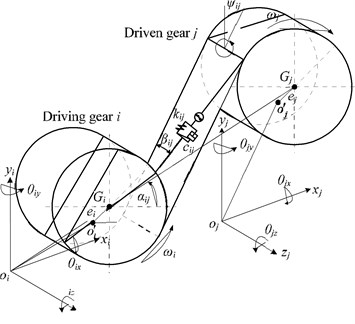
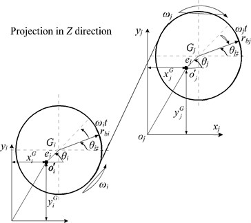
A mechanical model of the helical gear meshing is shown in Fig. 1. This system consists of the gear pair i and j, and the distance between the mass center o'and the centroid G' is the eccentricity, represented as ei, ej respectively.
Displacement vector of the mass center o' is represented as:
where x, y are DOFs in lateral direction with θz in torsional direction, z in axial direction, θx, θy in swinging direction. The positive direction is also shown in the Fig. 1.
Fig. 1Mechanical model of a gear mesh
a) Three-dimensional
b) Two-dimensional
Suppose that the gear mesh is a spring-damping element in which the stiffness of the spring is kij and the damping is cij [10, 11]. This element is on the meshing plane, it has an included angle of the helix angle βij with the slide line L and βij can be defined as:
Simultaneously, the relative position between gear i and gear j can be represented as αij (0≤αij<2π), which is defined as the included angle of x axis of driving gear i rotating to the center line in counterclockwise. Therefore, the included angle ψij between the positive direction of y axis and the meshing plane can be defined as:
where φij is the transverse pressure angle.
Introduce the signal function, sgn function:
Consider that there is a pair of gear meshing ij in which the driving gear is i and the driven gear is j, and both gears’ initial phase of the eccentricity is 0, hence the differential equations of motion considering meshing damping can thus be established as:
+sgn×cij˙pij(t)cosβij(rj-sgn×ejcos(θj-ψij))=sgn×Tj.
where θi=θzi+ωit, θj=θzj-ωjt, represent the total rotational angle of each gear, ωi and ωj are the rotation speed of gear i and j (positive direction is in counterclockwise direction), pij is the relative displacement of gear ij in the direction of meshing line, and pressure is positive while tension is negative is assumed. pij can be represented by basic displacement vector as follows:
Since θzi≪ωit, θzj≪ωjt therefore:
Combine the differential equation of motion, we can obtain:
where (Mij)12×12 is the mass matrix, (Kij)12×12 is the meshing stiffness matrix, (Cij)12×12 is the meshing damping matrix and (Gij)12×12 is the gyroscopic matrix given in Eq. (11). (F1ij)12×1 is the internal force produced by the variance of relative displacement generated from gears’ eccentricity along with the direction of meshing line, (Fsij)12×1 is the average transmitted internal force produced by gear’s eccentricity, and (Fw)12×1 is the system’s external force received, which consists of the driving matrix and resistance matrix and the centrifugal force.
where αij(4), αij(5), αij(10), αij(11) can be simplified as following since ri(j)≫ei(j):
sgn×ricosβij,sinψijcosβij,-cosψijcosβij,-sgn⋅sinβij,rjsinψijsinβij,
-rjcosψijsinβij,sgn×rjcosβij].
This paper used the QR damping methodology to analyze the system’s inherent characteristics and all damping can be represented by the Rayleigh Damping (α, β damping) [12], the Rayleigh Damping’s value can be taken as:
Generally, ζmr1=ζmr2=ζm and we take them as 0.04. Therefore Eqs. (18a) and (18b) can be simplified as:
where ζmr is the rth modal damping ratio, ωr is the rth natural frequency.
3. Solutions
For a vibration system with damping, the steady-state response to harmonic excitation force obtained by the mode superposition method (MSM) is:
In which u(r) is the rth vibration mode matrix, ωr is the rth natural frequency, ω is the external excitation’s frequency, φr and λr are system’s phase angle and frequency ratio respectively, details see reference [12].
4. Example and discussions
To verify the validity and correctness of the results, this paper adopted the ‘three shafts, 2-gear mesh gear train’ of reference [9] as the research model, shown in Fig. 2. Firstly, it analyzed the multi-gear-rotor-bearing system’s inherent characteristics with building the meshing stiffness matrix of the 12 working conditions. It then assessed the effect of meshing stiffness and other parameters on natural frequency of each order of the system.
4.1. Inherent characteristics analysis
4.1.1. Consider the influence of tooth direction, selection of driving shaft and rotation direction on inherent characteristics
This paper studied the influence of tooth direction, selection of driving shaft and rotation direction on natural frequencies of the system. Totally, there are 12 working conditions by combining the three factors above through permutation and combination, see Table 1.
Fig. 2Three-shaft-Two-gear mesh gear train in reference
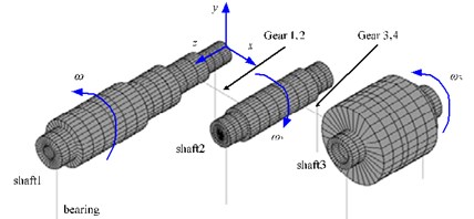
Table 112 working conditions
Left-lateral Right-lateral | Clockwise | Anti-clockwise |
Shaft 1 (driving shaft) | Working condition 1 2 | 3 4 |
Shaft 2 (driving shaft) | 5 6 | 7 8 |
Shaft 3 (driving shaft) | 9 10 | 11 12 |
Through our study it can be found out that three factors have considerable effect on natural frequencies, these are:
(1) Tooth direction of driving gear: Whether this direction is left-handed or right-handed affects the β’s value directly.
(2) Selection of driving shaft: Driving shaft’s being shaft 1, 2, or 3 influences α’s value directly;
(3) Rotation direction of driving shaft: clockwise or anti-clockwise. Rotation direction determines the value of the sgn function.
System’s parameters of 12 working conditions are shown in Table 2.
Table 2System’s parameters of 12 working conditions
Working condition | Helix angle β (°) | Azimuth angle α (°) | The value of sgn | ||
Mesh12 | Mesh34 | Mesh12 | Mesh34 | ||
1 | 20 | 20 | 0 | 0 | –1 |
2 | –20 | –20 | 0 | 0 | –1 |
3 | 20 | 20 | 0 | 0 | 1 |
4 | –20 | –20 | 0 | 0 | 1 |
5 | –20 | 20 | 180 | 0 | –1 |
6 | 20 | –20 | 180 | 0 | –1 |
7 | –20 | 20 | 180 | 0 | 1 |
8 | 20 | –20 | 180 | 0 | 1 |
9 | 20 | 20 | 180 | 180 | –1 |
10 | –20 | –20 | 180 | 180 | –1 |
11 | 20 | 20 | 180 | 180 | 1 |
12 | –20 | –20 | 180 | 180 | 1 |
From the calculation results it is clear that variance of working conditions has great effect on new frequency generating from coupling, see Fig. 3. Fig. 3 shows the first three orders of frequencies of the 12 working conditions, in which the first and second orders are new frequencies from coupling, and the difference of the first order frequencies among different working conditions is 96.47 Hz and the second order being 153.56 Hz, whereas the third order remains steadily.
Fig. 4 shows the vibration modes of the first three orders of natural frequencies in working condition 3, in which the first two orders are lateral-torsional coupling vibration modes from gears’ coupling and the third order is the first order bending vibration mode of shaft 1. Since the first two orders are generated from gears’ coupling, variance of gears’ parameters has impact on the both, while the third order is the bending vibration mode of a single shaft and such variance has no influence on it.
Fig. 3The first three order natural frequencies of geared system in 12 different conditions
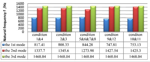
Fig. 4The first three modal shapes of geared system in the third condition
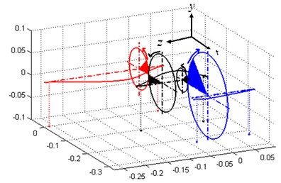
a) The first modal shape
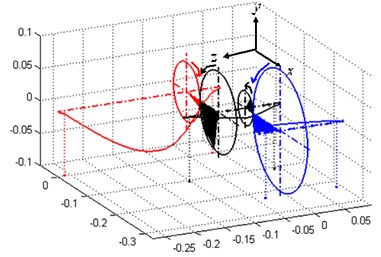
b) The second modal shape
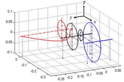
c) The third modal shape
4.1.2. Consider the influence of mesh stiffness on inherent characteristics
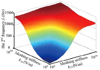
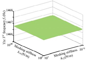
Many studies have proved that mesh stiffness has abrupt impact on the coupling new frequencies [7, 8]. Fig. 5 shows that mesh stiffness of the two pairs of gears affects the first three natural frequencies of the system. Specifically, it has substantial impact on the first two orders and no such influence on the third order. Moreover, new coupling frequencies rise along with the increase of meshing stiffness when it stays in [105, 107]. Natural frequencies also have abruptness. When mesh stiffness is larger than 107N/m, it has no such impact on natural frequencies.
Fig. 5The first three frequency curves with meshing stiffness k12 and k34
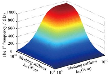
a) The first frequency curve with meshing stiffness k12 and k34
b) The second frequency curve with meshing stiffness k12 and k34
c) The third frequency curve with meshing stiffness k12 and k34
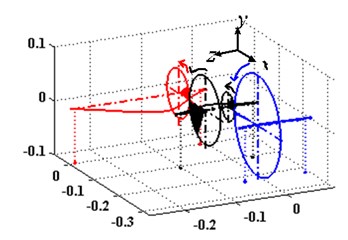
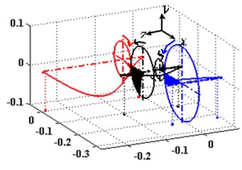
Through our research, it can be found out that mesh stiffness affects not only the new coupling frequencies, but also the mode shapes of the system. Fig. 6 shows the second order natural frequencies of the system with different mesh stiffness. After comparison, we can learn that both of the bending and torsion vibration mode shapes changed.
Fig. 6The first three modal shapes in different meshing stiffness
a)k12= 1×10⁵ N/m, k34= 1×10⁵ N/m
b)k12= 3.1×10⁸ N/m, k34= 4.14×10⁸ N/m
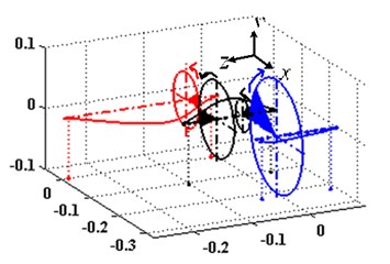
c)k12= 1×10¹⁰ N/m, k34= 1×10¹⁰ N/m
4.1.3. Consider the effect of mesh damping on inherent characteristics of the system
Studies that reveal the influence of mesh damping on a gear-rotor system’s inherent characteristics are not as abundant as that of mesh stiffness. Research of this paper shows that mesh damping also has a mutagenic impact on system’s natural frequencies, see Table 3. In Table 3, it is clear that the first and second orders increase substantially with the rise of the damping while the third order decreases slightly. In condition 1, system’s natural frequencies remain almost the same as the situation with no damping. Therefore, when meshing damping c12< 3.1×10² N/m·s and c34< 4.14×10² N/m·s, they have little impact on system’s natural frequency.
Table 3Natural frequencies corresponding to different mesh damping
c12= 3.1e2 N/m·s c34= 4.14e2 N/m·s | c12= 3.1e3 N/m·s c34= 4.14e3 N/m·s | c12= 3.1e4 N/m·s c34= 4.14e4 N/m·s | |
The 1st natural frequency | 808.33 Hz | 808.50 Hz | 825.18 Hz |
The 2nd natural frequency | 1345.6 Hz | 1346.1 Hz | 1379.5 Hz |
The 3rd natural frequency | 1468.0 Hz | 1466.8 Hz | 1466.8 Hz |
4.2. Transient response analysis
4.2.1. Comparison of responses considering static transmission error
Before unbalance response analysis, transient response analysis of the system has been finished based on static transmission error, and a comparison is then made. The amplitude of static error is generally consistent with that of the reference. Dynamic meshing force at the meshing point is then obtained, see Fig. 7.
Fig. 7The dynamic gear mesh force with the rotational speed
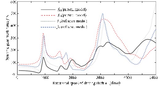
The following reasons leads to such error. The first one is the difference of geometric parameters in two papers: some parameters are not given in the reference and proper assumptions are made in this paper, examples of which are some geometric properties of the two rotors on shaft 2 are not given in the reference. The second one involves working condition. Working condition 3 is employed in this paper while no such information is given in the reference. The last one is the variance of calculation methods. Modal superposition method is adopted both, however the first twenty orders are superposed in this paper and no clear number of orders is given in the reference.
4.2.2. Comparison of responses when considering mesh damping
The effect of mesh damping on system’s inherent characteristics has been discussed in the sections above. From the study in this section, we can learn that mesh damping also affects responses considerably, see Fig. 8. It shows the comparison of the dynamic meshing force before and after the meshing damp is loaded.
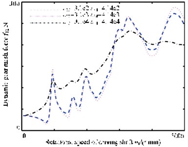
Fig. 9 illustrates the dynamic meshing force when considering three different kinds of meshing damping. It is shown that the influence of mesh damping on response increases when it rises. However, the increase of mesh damping does not decrease the peak of all resonance points, by contrast, when mesh damping c12= 3.1×10⁴ N/m·s and c34= 4.14×10⁴ N/m·s, the peak of the second and third order resonance points rises.
Fig. 8The dynamic gear mesh force curve before and after the meshing damp
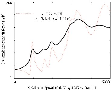
Fig. 9The dynamic gear mesh force curve with 3 different meshing damp
4.2.3. Comparison of responses when considering unbalance
(1) Selection of unbalance.
According to the National Standard, G6.3 is selected as the unbalance accuracy level and eccentricity can be eventually determined as 5 μm. Unbalance of each gear is shown in Table 4.
Table 4The value and location of unbalance
Location | Unbalance | Phase (°) | Location | Unbalance | Phase (°) |
Gear 1 | 4750 | 0 | Gear 3 | 1450 | 0 |
Gear 2 | – | – | Gear 4 | – | – |
(2) Unbalance response.
From Eq. (8) and Eqs. (13)-(15) it is known that the gears’ eccentricity will produce three kinds of forces F1ij, Fsij and Fw. The first two are internal force produced by eccentricity while the third being external force. Three kinds of force’s coupling becomes the unbalance excitation of the system. Fsij is relative to gears’ relative displacement and belongs to a nonlinear force, pij(t) and ˙pij(t) are selected as the average, ¯p12(t)= 0.9340967 μm, ¯p34(t)= 1.929237 μm, ¯˙p12(t)= –202.85 μm/s, ¯˙p34(t)= –2.8961 μm/s respectively, which are computed by the transient simulation.
Gear center’s unbalance response are shown in Fig. 10, in which Fig. 10(a) and Fig. 10(b) are gear 1 and 2’s axis orbits and Fig. 10(c) and 10(d) are gear 3 and 4’s axis orbits. From the figure, it is known that gear 1 and 4’s axis orbits are steady while gear 2 and 3’s are more complicated because of the gears’ coupling. Fig. 11 shows each gear center’s unbalance response curve responding to rotational speed’s change. It is clear that each node’s amplitude in x direction amplifies when rotational speed rises and gear 1 vibrates more seriously than others, which corresponds with Fig. 10.
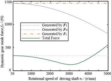
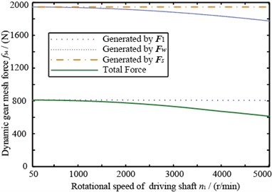
Two pairs of gears’ dynamic meshing force are shown in Fig. 12. From this figure, we can learn that the dynamic meshing force produced by unbalance has an obvious different trend with the transmission error, main reasons of which are: (1) Unbalance and transmission error have different excitation styles. Unbalance includes not only the transmission internal force from gear’s meshing but also the external force relating to rotational speed; (2) In unbalance response, gear’s relative displacement pij(t) includes the influence of gear’s eccentricity and this term’s magnitude is relatively large, however it does not exist in transmission error.
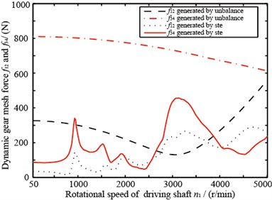
Shown in Fig. 13 are dynamic meshing force’s response curves responding to static transmission error and unbalance. Formants emerge when working rotational speed reaches the natural frequency when driven by static transmission error. While driven by unbalance, only few formants appear, and dynamic meshing force generated by unbalance is larger than that by static transmission error.
Fig. 10Gear axis orbit
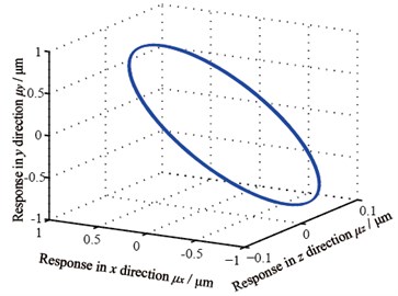
a) Gear 1’s axis orbit
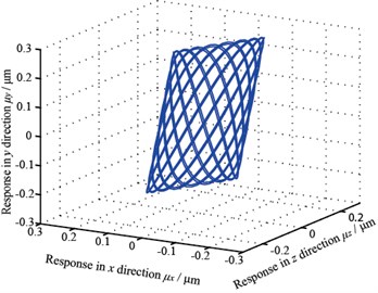
b) Gear 2’s axis orbit
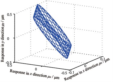
c) Gear 3’s axis orbit
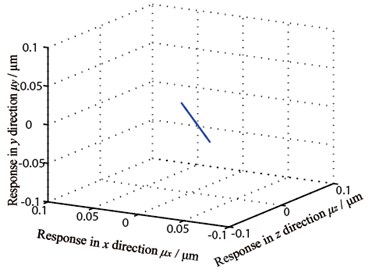
d) Gear 4’s axis orbit
Fig. 11Unbalance response curve
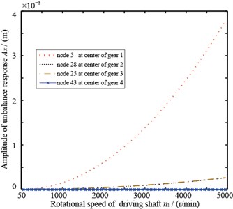
Fig. 12 illustrates that the amplitude of dynamic meshing force generated by F1 and Fs remains stable with rotational speed’s change, Fw’s amplitude decreases with rotational speed’s increase, a consequence of pij(t)’s eccentric term (see Eq. (6)).
Fig. 12The dynamic gear mesh force
a) Of gear 1 and 2
b) Of gear 3 and 4
Fig. 13The dynamic gear mesh force of gear 1 and 2
5. Conclusions
This paper has established a gear-rotor-bearing system and a transverse-rotational-axial-swinging dynamic model in which the effect from gyroscopic moment, gear meshing damping, bearing stiffness are considered. It then analyzed system’s inherent characteristics taking into account of the effect of driving gear’s tooth direction, driving shaft, and rotation direction on natural frequencies, and the effect of mesh stiffness and mesh damping on system’s inherent characteristics. Finally, it analyzed system’s response based on static transmission error and unbalance. It concludes as:
1) Driving gear’s tooth direction, selection of driving shaft, driving shaft’s rotation direction affect the coupling new frequencies greatly while no such effect has been observed in uncoupled frequencies. Among all 12 working conditions, the first order’s maximum natural frequency is 844.28Hz while the minimum being 747.81 Hz.
2) Mesh stiffness has great influence on natural frequency in some specific intervals while little in other intervals.
3) Mesh damping has an abrupt influence on natural frequencies. It affects little when itself being very tiny, its increase does not decrease all resonance points’ peak and may amplify one certain vibration peak.
4) When eccentricity exists at the gear’s wheel, gear’s excitation is the superposition of meshing internal force and external force, each node’s response to unbalance amplifies with rotational speed’s increase. Dynamic meshing force generated by unbalance is larger than that by static transmission error and only few formants appear. Therefore, eccentricity’s influence on dynamic meshing force should be taken into account when it exists.
References
-
Lin T., Ou H., Li R. A finite element method for 3D static and dynamic contact/impact analysis of gear drives. Computer Methods in Applied Mechanics and Engineering, Vol. 196, Issue 9, 2007, p. 1716-1728.
-
Sarkar N., Ellis R. E., Moore T. N. Backlash detection in geared mechanisms: modeling, simulation, and experimentation. Mechanical Systems and Signal Processing, Vol. 11, Issue 3, 1997, p. 391-408.
-
Yoon K., Rao S. Dynamic load analysis of spur gears using a new tooth profile. Journal of Mechanical Design, Vol. 118, 1996.
-
Skrickij V., Bogdevičius M. Vehicle gearbox dynamics: centre distance influence on mesh stiffness and spur gear dynamics. Transport, Vol. 25, Issue 3, 2010, p. 278-286.
-
Liang X. H., Zuo M. J., Pandey M. Analytically evaluating the influence of crack on the mesh stiffness of a planetary gear set. Mechanism and Machine Theory, Vol. 76, 2014, p. 20-38.
-
Kahraman A., Ozguven H. N., Houser D. R., et al. Dynamic Analysis of Geared Rotors by Finite Elements. DTIC Document, 1990.
-
Rao J., Shiau T., Chang J. Theoretical analysis of lateral response due to torsional excitation of geared rotors. Mechanism and Machine Theory, Vol. 33, Issue 6, 1998, p. 761-783.
-
Lee A. S., Ha J. W., Choi D.-H. Coupled lateral and torsional vibration characteristics of a speed increasing geared rotor-bearing system. Journal of Sound and Vibration, Vol. 263, Issue 4, 2003, p. 725-742.
-
Kubur M., Kahraman A., Zini D., et al. Dynamic analysis of a multi-shaft helical gear transmission by finite elements: model and experiment. Journal of Vibration and Acoustics, Vol. 126, Issue 3, 2004, p. 398-406.
-
Choi S.-T., Mau S.-Y. Dynamic analysis of geared rotor-bearing systems by the transfer matrix method. Journal of Mechanical Design, Vol. 123, 2001, p. 562-568.
-
Theodossiades S., Natsiavas S. Non-linear dynamics of gear-pair systems with periodic stiffness and backlash. Journal of Sound and Vibration, Vol. 229, Issue 2, 2000, p. 287-310.
-
Cai C., Zheng H., Khan M., et al. Modeling of material damping properties in ANSYS. CADFEM Users’ Meeting and ANSYS Conference, 2002, p. 9-11.
About this article
We would like to express our appreciation to Chinese National Natural Science Foundation (51405072), National Basic Research Program of China (973 Program) (2014CB046303).

