Abstract
To provide taxi capability without the use of engines or tractor, electric landing gear drive is considered as a potential system add-on. Driving torque and nose wheel steering angle controller are established which are verified by civil aircraft examples. Quasi-steady method is applied to calculate tire forces and moments. The ground steering response of aircraft is simulated, and then different taxi conditions including powered nose wheel mode and powered main wheel mode are compared. Two conclusions are obtained: Electric taxi system helps the aircraft turn on the spot and the turning radius is smaller than the aircraft using engines; differential powered main wheel mode has the minimum turning radius while turning-circle with uniform velocity, and it has smaller difference between two vertical loads of main landing gear than powered nose wheel mode.
1. Introduction
Rising fuel prices and environmental issues with aircraft emissions have resulted in the need for more efficient aircraft operations [1]. Since taxi time has been rising significantly over the last few years and will keep rising, electric taxi system (ETS) is rapidly developing as it uses auxiliary power unit (APU) to power the nose wheel (NW) or the main wheel (MW), which aims to allow the aircraft to begin pushback and taxi forward fully autonomously without using its main engines [2, 3]. The landing gear (LG) of aircraft with ETS is equipped with powered wheels which are actuated by electric traction motors with high torque density. The benefits of ETS include saving of fuel burn and repair costs, reduction of carbon emission and noise pollution, improvement of safety on apron and optimization of precision maneuvering etc. [4-6].
ETS has unique electronics system controllers which gives pilots total control of the aircraft’s velocity and direction during taxi operations. The two companies have chosen different solutions: WheelTug PLC, a Gibraltar corporation, uses electrically driven motors in the NWs of nose landing gear (NLG) to provide full mobility on the ground [7]; While Safran and Honeywell together under the project name Electronic Green Taxi System (EGTS) incorporate motors fitted to the MWs in main landing gear (MLG), without using its turbofans [8]. Both of plans reduce the amount of time that an airplane spends on the ground [9, 10].
The design and construction aspects of the powered wheel are addressed. A new ground handling model is established to analyze dynamic response of aircraft with ETS, in order to demonstrate a proof-of-concept of ETS. Simulation includes steering with uniform velocity. Aircraft ground dynamic responses of four different taxi conditions including powered NW and simultaneous, outside, differential powered MW are analyzed and compared. The virtual prototype and scaled test verify the feasibility of the powered wheel.
2. Virtual prototype
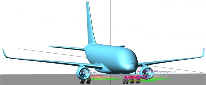
The tricycle LG has two MLGs behind center-of-gravity and a NLG ahead of center-of-gravity The aircraft simulated is chosen to be a Boeing 737-800 with ETS replacing the conventional LG. Boeing 737-800 operates short-haul to medium-haul routes and is in widespread use. The MTOW of modeled aircraft is 79010 kg and the location of center-of-gravity is between 26 % and 32 % of the mean airel chord. There are two tires per gear in the model. A detailed schematic is shown in Fig. 1.
Fig. 1The simulated aircraft equipped with ETS
ETS uses a series of hub mounted traction motors with high torque density to actuate the powered wheels. The initial design of the traction motor has a rotating armature and fixed field windings surrounding the permanent magnet synchronous machine (PMSM). The windings consist of tightly wound coils of wire fitted inside the motor case. It indicates that the best performances in terms of torque density are achieved by a single air-gap, outer rotor and PMSM option [11], which behaves exactly in the same manner as any brushless alternating current motor. The planetary gear assembly of the powered wheel comprises a ring gear, a sun gear, a plurality of planet gears configured to meshingly engage the ring gear and the sun gear and a carrier connected to the plurality of planet gears.
The virtual prototype and scaled model of the powered wheel with brushless direct current motors and gear systems mounted in NW are shown in Fig. 2.
Fig. 2The virtual prototype and scaled model of the powered wheel
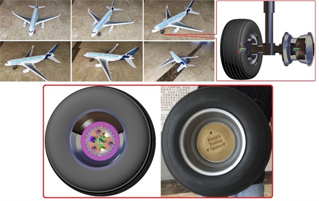
ETS has unique power electronics and system controllers. Power for ETS is transferred via cables to the NLG or MLG, where an electric engine is present to permit the wheel to freely spin during the pushback and taxi process.
3. Ground dynamic model
Dynamic differential equations are used to analyze the taxi phase at a speed below 20 knots (10 m/s) rather than touchdown process, so the forces generated by the wheels have a dominant effect over aerodynamic forces on the motion of the aircraft. The dynamic performance of powered wheels is analyzed on the basis of handling characteristic of inelastic support mass and overall system.
As ETS does not need propulsive force provided by engines, the loads on the whole aircraft except from the aerodynamic forces and gravitational forces are all applied at the tire–ground interface. The rolling contact is the core problem of tire/aircraft dynamics.
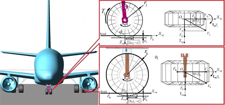
At low velocities (below 10 m/s) during the pushback and taxi process, normal force acting on the tire has no obvious change and positive inclination angle is close to zero during the taxi process. As tire overturning moment and positive inclination angle are not major factors, Fiala tire model [12] is used in software ADAMS. Aircraft tire is considered as the beam element with lateral elastic deformation. The vertical force component on the tire can be approximated by a linear spring and damper system, and the contact method supplies the tire model with the effective road plane for the tire deflection/penetration calculation. Tire longitudinal and lateral slip effects can be considered unrelated.
The loaded tire model in wheel reference frame is shown in Fig. 3, as the electro engine is incorporated in the NLG wheel rim (powered NW mode).
Fig. 3The loaded tire model in wheel reference frame (powered wheel in NLG)
4. Control system model
4.1. Requirements from the taxi mission
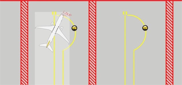
Dynamic differential equations focus on the ground steering response of aircraft with ETS. According to WheelTug PLC, an aircraft with ETS can turn sideways at the gate so the pilot does not have to perform pushback. Fig. 4 provides the aircraft’s turning on the spot with a NW steering angle of 73.5° [13], and the turning radius of center-of-gravity is close to 4.5 m.
4.2. Driving torque model
To ensure the aircraft’s steering with uniform velocity, the driving torque of the th powered wheel changes with the th wheel’s velocity, as follows:
where is the maximum variation of the driving torque of the th powered wheel; is the taxi speed of the th powered wheel; is a small variable quantity of the taxi speed which is used to maintain the concrete taxi speed according the speed requirement to the beginning of the runway.
Fig. 4Turning on the spot with a NW steering angle of 73.5°
4.3. Steering response model
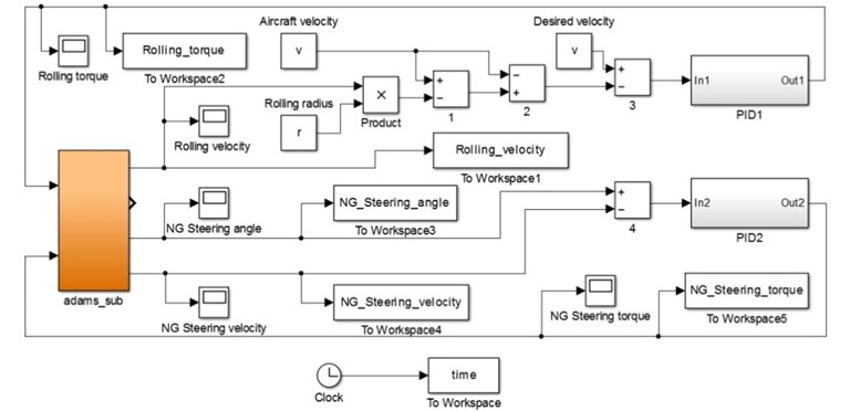
The closed-loop control laws integrated within the aircraft avionics must ensure convergence, rapidity, precision and robustness to perturbations within components' intrinsic limits [14]. A Matlab/Simulink model in Fig. 5 is established based on the previous mathematical model.
The multiple thresholds PID controller is written by trapezoid formula and first order two-point formula, as the differential equations are solved by fourth order Runge-Kutta method [15].
Fig. 5Control model architecture
5. Simulation results
Based on the ADAMS simulation platform, a Boeing 737-800 virtual prototype with ETS is established. Dynamic simulation is performed for comparison between powered NW and powered MW with the same LG configuration and parameters. The taxi speed, NW steering angle and MW differential driving torque can influence aircraft’s turning radius. The NW steering angle of 73.5° and taxi speed of 3 m/s during turning-circle are determined during the steering process.
The turning radius of outside powered MW is smaller than the turning radius of inside powered MW [16], so only outside powered MW mode is chosen for simulation. The parameters of four taxi conditions used in following simulation are given in Table 1.
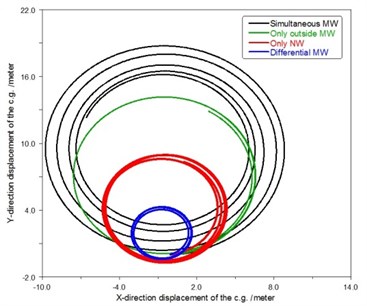
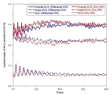
Ground steering response of aircraft with ETS including motion track of center-of-gravity of aircraft in horizontal plane and vertical loads of LG are shown in Fig. 6(a), (b), respectively.
Table 1Four taxi conditions
Taxi condition number | Taxi condition mode | Powered wheel in use |
1 | Simultaneous MW | Outside and inside MW |
2 | Only outside MW | Only outside MW |
3 | Only NW | Only NW |
4 | Differential MW | Outside and inside MW |
Fig. 6Motion track of center-of-gravity of aircraft in horizontal plane
a)
b)
The turning radius of the aircraft with powered NW fluctuates around 4.5 m and conforms to the taxi requirements and mission in Fig. 4.
When the NW steering angle and the taxi speed are constant, simultaneous MW mode has the largest turning radius. Compared with powered outside MW mode, powered NW mode can decrease the turning radius. MW differential driving torque mode has the minimum turning radius.
Compared with powered NW mode, differential powered MW mode decreases the difference between two MLG’s vertical loads of conventional tricycle LG aircraft under the same taxi condition. NLG’s vertical loads of different modes are almost the same at the beginning of turning-circle. However, the vertical load of NLG of powered NW mode gets smaller than differential powered MW mode over time.
6. Conclusions
A new mathematic model of ground movement of aircraft with ETS is established, considering the six-degree-of-freedom aircraft body, the flexible LG’s main strut and the powered wheels mounted in different LGs. Dynamic simulation is used to output ground steering response of aircraft with ETS. Two conclusions are obtained.
Driving torque and nose wheel steering angle controller are adopted to ensure the aircraft’s turning-circle with uniform velocity.
Electric taxi system helps the aircraft turn on the spot and the turning radius is smaller than the aircraft using engines. Differential powered MW mode has the minimum turning radius, and the difference between two MLG’s vertical loads of differential powered MW mode is smaller than powered NW mode during the process of steering.
References
-
Wijnterp C., Roling P. C., de Wilde W., et al. Electric taxi systems: an operations and value estimation. 14th AIAA Aviation Technology, Integration, and Operations Conference, 2014.
-
Wollenheit R., Mühlhausen T. Operational and environmental assessment of electric taxi based on fast-time simulation. Transportation Research Record: Journal of the Transportation Research Board, Vol. 2336, 2013, p. 36-42.
-
Hospodka J. Cost-benefit analysis of electric taxi systems for aircraft. Journal of Air Transport Management, Vol. 39, 2014, p. 81-88.
-
Re F. Viability and state of the art of environmentally friendly aircraft taxiing systems. IEEE Electrical Systems for Aircraft, Railway and Ship Propulsion (ESARS), 2012, p. 1-6.
-
Dzikus N., Wollenheit R., Schaeffer M., et al. The benefit of innovative taxi concepts: the impact of airport size, fleet mix and traffic growth. AIAA Aviation Technology, Integration, and Operations (ATIO) Conference, German Aerospace Center (DLR), 2013.
-
Roling P., Sillekens P., Curran R., et al. The effects of electric taxi systems on airport surface congestion. 15th AIAA Aviation Technology, Integration, and Operations Conference, Vol. 2592, 2015.
-
Gubisch M. WheelTug is not for turning: manufacturer of nose-gear electric taxi system remains confident in its product despite lack of support from airframers. Flight International, Vol. 185, Issue 5426, 2014.
-
Ganev E., Chiang C., Fizer L., et al. Electric drives for electric green taxiing systems. SAE International Journal of Aerospace, Vol. 9, 2016, p. 62-73.
-
Driving Aerospace, Components. WheelTug, http://www.wheeltug.gi/components.shtml, 2013.
-
EGTS Electric Green Taxiing System, Overview. http://www.greentaxiing.com/overview.html, 2013.
-
Galea M., Xu Z., Tighe C., et al. Development of an aircraft wheel actuator for green taxiing. IEEE International Conference on Electrical Machines (ICEM), 2014, p. 2492-2498.
-
Tire Modeling ADAMS/Aircraft: Basic Tire Model. MSC, Software Corporation, 2005.
-
Driving Aerospace. WheelTug Company, http://www.sts-technology.com/docs/WheelTug-CVP-28Nov11-16-9.pdf, 2012.
-
Guo R., Zhang Y., Wang Q. Comparison of emerging ground propulsion systems for electrified aircraft taxi operations. Transportation Research Part C: Emerging Technologies, Vol. 44, 2014, p. 98-109.
-
Hull D. G. Fourth-order Runge-Kutta integration with step size control. AIAA Journal, Vol. 15, Issue 10, 1977, p. 1505-1507.
-
Rankin J., Coetzee E., Krauskopf B., et al. Bifurcation and stability analysis of aircraft turning on the ground. Journal of Guidance, Control, and Dynamics, Vol. 32, Issue 2, 2009, p. 500-511.
