Abstract
A free vibration analysis is carried out on a discretized Fokker aircraft with an integrated bio-dynamic pilot model. It is an attempt to study the dynamic behavior of bio-dynamic pilot model, when the vibration is induced in aircraft. The system is assumed to have an eleven degree-of-freedom including bouncing motion of tyres, fuselage, seating system and pilot’s head along with angular pitching and rolling of fuselage. A robust model is developed using both MatLab Simulink and MSC Adams. System parameters are borrowed from the earlier reported literature of the present authors. Simulation is carried out for various initial input conditions. Responses of fuselage and pilot’s head are reported for initial displacement considered at nose landing tyre. Natural frequencies of the system are generated and compared with earlier reported results. A good agreement is noticed among the results obtained via all the three of analysis approaches.
Highlights
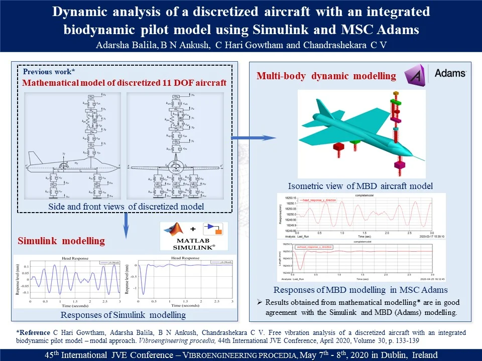
- Simulink and Multi-body dynamic models of an eleven DOF discretized Fokker aircraft with an integrated bio-dynamic pilot model are developed.
- It is an attempt to study the dynamic behavior of bio-dynamic pilot model, when the vibration is induces in aircraft.
- Free vibration analysis is carried out to obtain natural frequencies and responses of the aircraft system.
- The results obtained are in very good agreement between two simulation models and as well with results reported in previous mathematical model work.
- Developed model can readily be used/altered to carry out various dynamic simulations for different aircrafts and bio-dynamic pilot systems.
1. Introduction
Innovation of aircraft is a major breakthrough in the modern world. The network of aircrafts connects distant destinations very fast and safe, which makes it an important transportation industry. In the recent days, Aviation industry is striving to improve the design and performance of aircraft to meet the market demand for more robust aircraft. Aircrafts are often subjected to several external excitations like impacts of landing and runway surface irregularities. The induced vibrations deteriorate pilot’s capability to maneuver aircraft leading to reduced performance. To make earlier predictions and improvise decision making in tackling the unwanted vibrations, it is necessary to understand the dynamic behavior of aircraft and pilot systems. Conventional mathematical models are developed in prior researches to obtain dynamic characteristics of simplified aircraft systems. Now-a-days model-based designing software packages are used readily to simulate the aircraft system.
Klee and Allen [1] described the development of Simulink model for various dynamic systems using equations of motion. Using simulations, responses of the system for various standard inputs are presented. Phalke and Mitra [2] developed a MatLab Simulink model representing two DOF quarter-car system to investigate the dynamic response of vehicles under road induced vibrations. The effect of damping coefficient, stiffness and velocity on ride comfort and road holding are analyzed. Sharma et al. [3] developed ten DOF full-car model with integration of primary and cabin suspension in the Simulink environment to investigate the effect of cabin suspension on the ride comfort over primary suspension system. Responses of the combined primary and cabin suspension are compared with the response of primary suspension under step excitation. Sivakumar and Haran [4] developed a six DOF Fokker aircraft mathematical model with active landing gear systems. Simulation is performed for a Simulink model to retrieve response curves for various runway inputs and reported the superiority of active landing gear systems. Teixeira et al. [5] performed the analysis on dynamic behaviour of electric bus model for various maneuvering conditions and bumps using MSC Adams. Wideberg et al. [6] developed a fourteen DOF dynamic model of an electric vehicle with motors and four wheels. A detailed model is built in Adams platform and all elements of the actual vehicle such as coil springs, telescopic shock absorbers and pneumatic wheels are considered for the study. Gowtham et al. [7] developed a mathematical model of eleven DOF discretized aircraft with an integrated bio-dynamic pilot model. The dynamic characteristics of the system viz., natural frequency, mode shapes and responses using modal approach are reported.
The present work is the extension of [7], in developing a simulation models using MatLab Simulink and MSC Adams. It is an attempt to study the dynamic behavior of bio-dynamic pilot model, when the vibration is induced in aircraft. Free vibration analysis is carried out to retrieve responses for various initial conditions and natural frequencies. The results obtained are compared with [7] and are reported in the present work. A good agreement is noticed among the results obtained via all the three approaches.
2. Simulink modelling and Free vibration analysis
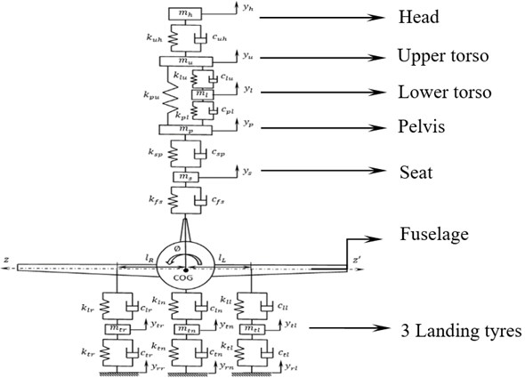
An eleven DOF discretized Fokker aircraft with an integrated bio-dynamic pilot model is developed using MatLab Simulink. The system parameters are considered as mentioned in the preceding work [7]. Six DOF correspond to aircraft having bouncing motions of three landing tyres and fuselage along with angular pitching and rolling motions. The remaining five DOF correspond to bouncing motions of bio-dynamic pilot masses. The schematic of an eleven DOF aircraft system with an incorporated bio-dynamic pilot model is shown in Fig. 1.
Fig. 1Front view of discretized aircraft system with an integrated bio dynamic pilot model
The equations of motions for the eleven DOF system are obtained by using Newton’s second law of motion. Free body diagrams for the pilot’s head, upper torso, seat and fuselage in bouncing motion are shown in Figs. 2-5 respectively.
Equation of motion for bouncing of head is expressed as:
Equation of motion for bouncing of upper torso is expressed as:
Equation of motion for bouncing of seat is expressed as:
Fig. 2Free body diagram for bouncing of pilot‘s head
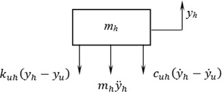
Fig. 3Free body diagram for bouncing of upper torso
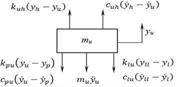
Fig. 4Free body diagram for bouncing of pilot’s seat mass
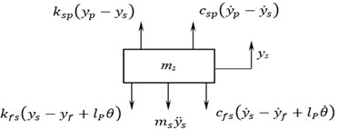
Fig. 5Free body diagram for bouncing of fuselage
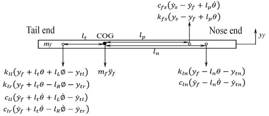
Equation of motion of fuselage () in bouncing is expressed as:
Similarly, the equations of motion for other masses in their respective degree-of-freedom are derived. The derived governing equations are expressed as follows to facilitate expressing it in Simulink platform:
where, 1, 2, … and 11, is th mass, and denotes stiffness and damping forces acting on the mass respectively and is displacement of the th mass. The in-built functions/options available in Simulink are used to represent the set of equations.
Free vibration analysis is carried out for the developed model. System parameters are explicitly specified and executed in MatLab console before running the simulation. An initial vertical displacement of 1 mm is considered for the nose landing tyre mass in upward direction. The simulation duration is considered as 3 seconds. Fig. 6(a) and (b) shows free vibration bouncing response of the fuselage under both undamped and damped condition respectively.
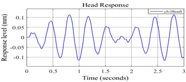
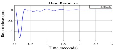
Fig. 7(a) and (b) represents the pilot’s head bouncing response under undamped and damped conditions respectively.
Fig. 6a) Undamped response of fuselage bouncing, b) damped response of fuselage bouncing
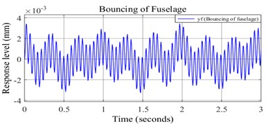
a)
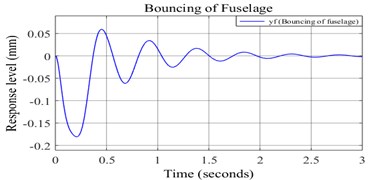
b)
Fig. 7a) Undamped response of pilot’s head, b) damped response of pilot’s head
a)
b)
It is noticed the amplitude of fuselage bouncing is in the order of 10-3 mm, which is very less compared to the pilot’s head bouncing. It is clear from the damped response that the pilot’s head bouncing comes to steady state faster than fuselage bouncing.
3. Multi-body dynamic modelling
Taking advantage of model-based designing, an eleven DOF discretized Fokker aircraft model with an integrated bio-dynamic pilot model is built using MSC Adams as shown in Fig. 8.
Fig. 8(a-d) represents CAD model, iso-metric, front and side views of the aircraft view in ADAMS respectively. The fuselage is initially modelled in SolidWorks and is imported into Adams platform. Rest of the masses are modelled in Adams environment. The fuselage is given an inline primitive joint and rest of the masses are assigned with a translational joint at the centre of masses. It is assumed that three landing tyre masses are in contact with the ground.
4. Free vibration analysis in Adams
MBD simulation is carried out by deactivating the gravity in Adams environment. An initial vertical displacement of 1mm is considered for the nose tyre mass in upward direction. The system is simulated with help of simulation plugin keeping the step size as 0.001 for a duration of 3 sec. Fine step size leads to obtain a fine tuned response. To obtain the responses for desired mass, the displacement motion of centre of mass in vertical direction is plotted against time.
Fig. 9 and 10 represents the undamped and damped bouncing responses of fuselage respectively.
Fig. 8Fokker aircraft model
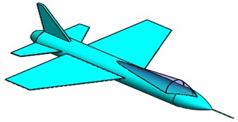
a) CAD Model of aircraft in SolidWorks
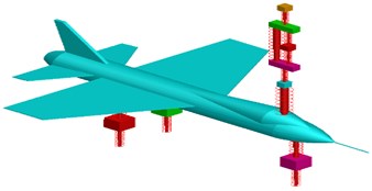
b) Isometric view of the system in Adams
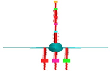
c) Front view of the system in Adams
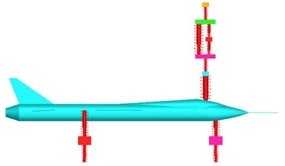
d) Side view of the system in Adams
Fig. 9Undamped bouncing response of the fuselage

Fig. 10Damped bouncing response of the fuselage

Fig. 11 and 12 represents the undamped and damped bouncing responses of pilot’s head respectively.
Fig. 11Undamped bouncing response of pilot’s head

Fig. 12Damped bouncing response of pilot’s head

Undamped responses vary in a sinusoidal form with respect to the time. It is observed that the fuselage and pilot’s head attains steady state in 2.5 sec and 1.8 sec respectively for the damped system and is similar to the results obtained in Simulink. The response level of the system is significantly low for an initial displacement of 1 mm.
The natural frequencies of the system are obtained upto six modes are compared and tabulated in Table 1.
Table 1Natural frequencies from MBD simulation and mathematical model [7]
Mode | Natural frequency (Hz) | % error | |
Present | Ref. [7] | ||
1 | 0.74 | 0.75 | –1.33 |
2 | 1.02 | 1.02 | 0 |
3 | 2.49 | 2.48 | 0.40 |
4 | 3.04 | 3.03 | 0.33 |
5 | 11.56 | 11.56 | 0 |
6 | 12.69 | 12.69 | 0 |
It is observed that the calculated percentage errors are very negligible. The obtained natural frequencies and undamped free vibration responses from the simulations are in very good agreement with the mathematical model [7].
5. Conclusions
Simulink and MSC Adams platforms are used to develop an eleven DOF discretized Fokker aircraft with an integrated bio-dynamic model of pilot. Free vibration analysis of both the models are carried out. Care is taken in choosing the step size in Adams environment. The natural frequencies and responses are generated and reported. The obtained simulation results are in very good agreement with the results reported [7]. Developed model can readily be used/altered to carry out various dynamic simulations for different aircraft and bio-dynamic pilot systems.
References
-
Harold Klee, Randal Allen Simulation of Dynamic Systems with MATLAB and Simulink. Second edition, CRC Press, 2011.
-
Phalke Trupti P., Mitra Anirban C. Analysis of ride comfort and road holding of quarter car model by Simulink. Materials Today: Proceedings, Vol. 4, Issue 2, 2017, p. 2425-2430.
-
Sharma S. K., Vinod Pare, Manoj Chouksey, Rawal B. R. Numerical studies using full car model for combined primary and cabin suspension. Procedia Technology, Vol. 23, 2016, p. 171-178.
-
Sivakumar S., Haran A. P. Mathematical model and vibration analysis of aircraft with active landing gears. Journal of Vibration and Control, Vol. 21, Issue 2, 2015, p. 229-245.
-
Teixeiraa Ricardo R., Moreiraa Sergio R. D. S., Tavaresa S. M. O. Multibody dynamics simulation of an electric bus. 1st International Conference on Structural Integrity, Procedia Engineering, Vol. 114, 2015, p. 470-477.
-
Wideberga Johan, Bordonsa Carlos, Luqueb Pablo, Mántarasb Daniel A., Marcosc David, Kanchwalad Husain Development and experimental validation of a dynamic model for electric vehicle with in hub motors. Procedia – Social and Behavioral Sciences, Vol. 160, 2014, p. 84-91.
-
C Hari Gowtham, Adarsha Balila, B N Ankush, Chandrashekara C V Free vibration analysis of a discretized aircraft with an integrated biodynamic pilot model – modal approach. Vibroengineering Procedia, Vol. 30, 2020, p. 133-139.
