Abstract
A collapse of 3 guyed portal towers in a 220 kV transmission power system were caused by short period of strong wind. In order to unmask accident, various methods are used, such as scene investigation, material test and FE method. The reasons caused the collapse accident are obtained in this paper, and some improvement measures are recommended for sake of continuing maintenance.
1. Introduction
Transmission power tower plays an important role in transmission power line, supporting the transmission power line and ensuring safety distance [1] from ground. Severe collapse accident may lead to large area electricity blackout and myriad economic loss. It is essential for grid operation [2, 3] to detect the reason and characteristics of the collapse of transmission power tower and propose practical improvement solutions for further maintenance.
2. Accident profile
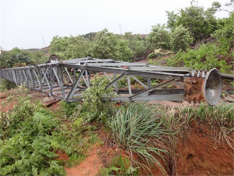
The accident occurred on April 24th, 2012. The collapses of three transmission power towers named respectively #54, #55 and #56 in the 220 kV transmission power system are line towers. The collapse accident of the #54 tower is shown in Fig. 1. The transmission power system spans 1834 km and came into service in January 2005. The transmission power system was designed under a wind speed of 25 m/s. The three towers broken down on the direction vertical to the transmission power line. Furthermore, the earth wire bracket of #57 strain tower also has been damaged. Discharge point was found at the #53 transmission power tower.
3. Material sampling test
Several tests, like Zn-coat Thickness test, ingredient test and mechanic performance test, are executed on the materials from #54 and #55 tower including main shaft from cross arm, upper and middle part, leg shaft, and sub-shaft. Consequently, the tests show the sub-shaft of #55 tower fail to meet the requirement, while other material are up to standard.
4. Calculation of strong wind load for slave tower
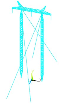
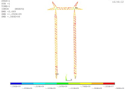
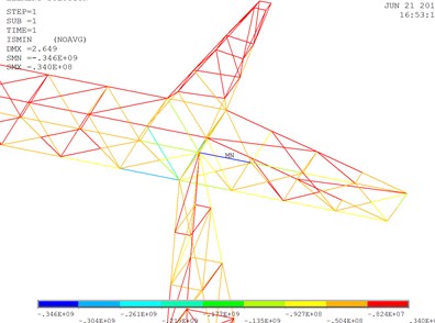
The finite element method is used to analyze the #54guyed portal tower (ZH3-30) under strong wind condition [4, 6]. The finite element model of #54 transmission power tower is shown in Fig. 2. It contains 1329 beam elements. Through the analysis, it shows that the maximum bearing wind velocity is 30.2m/s. When the speed goes to 30.2 m/s the shaft of cross arm yielded and the stress of the shaft exceeded the yield strength of Q345. As a result, the tower collapsed which is showed in Fig. 3 and Fig. 4. However, based on circumstance around the tower, the wind speed when the collapse occurred can be estimated reasonably below the maximum speed. It’s necessary to consider the influence of fluctuating wind in the continuing works, in order to simulate the real loadings on the transmission power tower for the sake of safety.
Fig. 1The collapse accident of the #54 tower

Fig. 2The finite element model of Guyed portal tower

Fig. 3Stress nephogram overall

Fig. 4Stress nephogram local

5. Reasons for towers collapsing
Base on the analysis above, the #54 ZH3-30 guyed portal tower is up to the requirement and resist the wind at a velocity of 25 m/s. Considering the discharge point of #53 strain tower and the insulator and anchorage point of #54 guyed portal tower, the collapse of the guyed portal tower wasn’t caused by strong wind at one time. The main incentive of collapse is the disjunction of the spherical steel plate and the positing steel bar at the basis of the tower. Moreover, the length of the positing steel bar is only 40 mm. Fixed plane is not taken into account when designing. In summary, the disjunction happened firstly, and then the displacement continuing increase caused by the vibration which induced by strong wind, finally the tower collapsed because of the offset of gravity center.
What’s more, the bolt that connect the guy wire and the #54 tower has dropped. That means that the maintenance work is insufficient. So the natural frequency is lower than usual, thus the vibration of the tower become more severe, and weaken the ability of resisting the wind load.
Consequently, the main reason of the #54 220 kV guyed portal transmission power tower’ collapse is the failure design of the tower basis. At the same time, the insufficient maintenance is also a reason that can’t be ignored, it is the breakdown of the basis leg of the #54 caused the collapse of the three transmission power towers.
6. Conclusion
The main reason for the collapse of the 220 kV transmission power system in this paper is that the design of the positing steel bar is as short as 40 mm, and the fixed plane is not taken into consideration. In extreme conditions, the leg of the would be pulled off by the force caused by strong wind. And the positing steel bar was pull off from the basis. The collapse then occurred.
The bolt that connect the guy wire and the #54 tower has dropped. That means that the maintenance work is insufficient.
In order to prevent from collapse of transmission power tower, some improvement and measures should be taken. Especially, the design of the positing steel bar of the basis leg of the tower should be concerned. The tower that already constructed should install a fixed plane and lengthen the positing steel bar as well.
References
-
Ouyang Ke-jian, Liu Jun, Chen Hong-dong, et al. Analysis of breakage of sub-conductors of 500 kV transmission line. Power System Construction, Vol. 13, Issue 3, 2012, p. 74-78.
-
Xie Qiang, Zhang Yong, Li Jie Investigation and analysis of wind-induced falling tower accidents on squall line of No. 5237 line in 500kV line in East China power grid. Power System Technology, Vol. 6, Issue 3, 2006, p. 23-29.
-
Zhang Yong Current situation and countermeasure of transmission line wind disaster prevention. East China Electric Power, Vol. 10, Issue 6, 2006, p. 28-31.
-
Zhang Dian-sheng Design manual of high voltage power transmission line in power engineering. China Electric Power Press, Beijing, 2002, p. 337-344.
-
110~750 kV Overhead Transmission Line Design Specification. GB50545-2010, China Electric Power Press, 2010.
-
Technical Specification for Structural Design of Pole and Tower of Overhead Transmission Line. DL/T5154-2002, China Electric Power Press, 2002.
