Abstract
In the paper, optical-based measurement methods for calculating the deflection and vibration of overhead lines are presented. The authors describe the state of the art in the field of non-contact examination of static and dynamic overhead transmission line characteristics, and propose concepts of vision-based measurement systems for both static and dynamic states of a structure. The system devoted to static measurements is based on a digital SLR camera and image-processing software used for the acquisition and interpretation of data. The digital image correlation method, implemented in Wiz2D software, is applied to compute the displacement of the transmission line cable with respect to a known baseline position. Dynamic characteristics of the structure are obtained using a stereo-vision system consisting of two high-speed digital cameras. Corresponding points in two video sequences of the vibrating cable are tracked using TEMA software. 3D positions in a camera frame of reference and displacements are computed using a 3D reconstruction method. The paper describes two series of experiments conducted on a lab setup and the obtained results are examined and discussed.
1. Introduction
In the classical measurement of displacements and vibration, contact sensors, such as accelerometers, force transducers or strain gauges are used. Application of these types of sensors requires them to be connected to the examined structures. In many cases, this is not possible or desirable, because of the operational conditions, like high temperature or technological constraints. This kind of problem also arises in the case of overhead high voltage transmission lines. It is necessary to monitor the sag of the cables with respect to the ground level or their vibration which is excited by the environmental conditions. It is necessary to develop non-contact measurement techniques. There are many such methods reported in the literature [1, 2]. The simplest one uses geodesic, high-precision tools, such as total stations. The method is easy to implement, but requires qualified experts and, therefore, its cost is high. There are techniques which use current, temperature or stress data in order to indirectly estimate sags. These methods are not expensive but require complex algorithms and are characterized by a high error value. Laser-based methods are being developed, but they are restricted to single point measurements. An alternative solution may, however, utilize contact measurements – with piezoelectric sensors bonded to the cable attachments to indirectly assess its tension – via electromechanical impedance [3] or ultrasonic waves excited by piezoelectric [4, 5] transducers. The usage of the advanced signal processing devices and methods is also reported [6, 7].
Vision systems, as easy-to-use, high-precision and universal tools, can be a good alternative for acquiring the displacement and vibration signals of transmission line cables. They can be applied to examine cables in operational conditions. There are many applications of vision-based systems in the monitoring of high-voltage transmission lines. The main areas of use can be classified into major groups: 1) an extraction of transmission line cables for later analysis, 2) an estimation of ice cover thickness and damage detection, 3) measurement of displacements of measurement points. The paper [8] presents an example of the first group. The authors developed an image segmentation algorithm to extract transmission lines from the background. The automatic curve detection was carried out using a UAV inspection robot. In order to process images of low contrast, the Otsu method based on genetic algorithms and simulated annealing was applied [9]. In the paper [10], segmentation was performed using genetic algorithms and particle swarm optimization methods. The impact of variable lighting conditions on the detection of cables was removed by the application of homomorphic filters [11]. The automatic detection of transmission lines and classification of different types of transmission towers was presented in the paper [12]. The classification of towers was performed based on extracted edge images. The paper [13] represents a method that belongs to the second group of applications. A vision system was used to measure the thickness of ice on the transmission line cable based on a comparison between the edge images of ice-covered cables and ones without an ice cover. Two methods of edge detection were implemented: wavelets and image morphology. The authors of [14] presented a system for ice cover monitoring. The image processing consists of multiple steps, with the main ones being background subtraction, edge extraction and classification of ice cover types. The system can be applied for on-line monitoring of ice thickness. The paper [15] shows an application of 3D vision methods to measure ice thickness. The problems of image points’ correspondence were solved by an algorithm based on analysis of edges, epipolar lines and digital image correlation (DIC). Manitoba Hydro presented “the Ice Vision System” [16] dedicated to the early detection of icing, measurement of ice accumulation and classification of the type of icing. The system was mounted on 66 kV transmission lines. Ice cover is analyzed based on its binary image. Geometrical parameters (e.g. area, diameter and compactness coefficient) are computed on-line. Damage detection [17] methods for transmission line cables are also being developed. The paper [18] presents a vision system for lightning-induced cable damage detection. The system detects arc-shaped damage as well as cuts and cracks of cable bundles. The authors of the paper [19] present an example of an application belonging to the third group. The measurement of a transmission line cable’s vibration was carried out in order to estimate the parameters of the structure and to predict the occurrence of damage. The algorithm extracts edges, reconstructs vertical displacements of measurement points and computes the Fourier transform of the obtained displacement amplitude signal. The paper [20] describes a tool which aids vision-based modal analysis of transmission line cables. The image sequence was captured by a camera influenced by external vibrations. Therefore, the frames were blurred due to relative camera and object motion. The authors proposed multi-pattern matching based on DIC, which reconstructs vibration signals. The phenomenon of inducing cable vibrations due to the shedding of an ice cover is investigated in the paper [21]. A vision-based system is used to measure the amplitude, frequency and damping of a vibrating cable. A ball marker was used as a measurement point. The papers [22, 23] show an application of computer vision for geometry estimation and localization of measurement points in the preliminary steps of modal experiments, for the measurement of vibration signals, vision-based modal analysis and damage detection and localization based on vision data. An extension of the proposed method to a full 3D system was proposed in [24]. The paper [25] presents a non-contact method for the measurement of tensile forces in the suspension cables of bridges. A DIC algorithm was applied for displacement computation. The compensation of the random motion of a camera due to wind or vibration was proposed. The correction is provided by the observation of a fixed object on the scene, e.g. a distant building. Tension in the cables was estimated based on dynamical response and resonant frequencies. A damage detection method based on mode shapes was introduced.
The authors of the paper propose two vision-based systems for transmission line monitoring. The first solution consists of a digital SLR camera and is applied in the measurement of the changes in the cable’s sag. The displacement is computed using a digital image correlation coefficient and can be performed on markers, as well as the natural texture of the cable. The second solution is a 3D vision system to compute the dynamic characteristics of the transmission line cables. It consists of two high-speed digital cameras and a set of markers mounted on the surface of the cable. Full 3D trajectories of vibrating points are reconstructed using a stereo-vision algorithm. The paper presents the results of two lab experiments. The static sag of the cable loaded by a set of weights and the frequency response of the cable are investigated. Section 2 introduces two developed vision-based measurement methods for the monitoring of transmission line cables. Section 3 describes the lab setups and gives results of the experiment and Section 4 provides the conclusions of the paper.
2. Measurement methods
In the following section, two vision-based measurement methods are characterized. The first system is used for measurement of a cable’s sag and the second one provides data for vibration analysis of the structure.
2.1. Measurement of a cable’s sag
The first vision-based system measures the sag of the analyzed transmission line cable. The system uses a digital SLR camera mounted on a tripod. It computes the displacements of measurement points using the DIC method. It is possible to obtain the displacement of a single point using a marker placed on the cable’s surface or a dense field of displacements at many control points using the natural texture of the examined object. The system can be used for off-line and on-line measurement sessions [26, 27]. In addition, the field of view can be varied, depending on the desirable accuracy of the system. The system requires a baseline and, therefore, can be used only for relative sag measurements, e.g. monitoring of a change in sag during extended periods of time.
The measurement procedure consists of the following steps: 1) system calibration, 2) preparation of a lab setup, 3) acquisition of reference images, 4) measurement session preparation, 5) scaling and 6) measurement using a DIC algorithm. The system is calibrated using a flat checkerboard pattern. The parameters obtained in the calibration step are used to remove distortions introduced by the optics. Next, the markers are placed on the structure. This step may be omitted if one only uses a texture already available on the surface. The camera must be placed on a tripod and positioned with respect to the hung cable. Next, the reference image is acquired. This image is used in the measurement session preparation step. The user decides on the positions of points of interest, the number of them and the size of the pattern window centered at each of the chosen points. A scaling pattern is used to compute the scale coefficient. Next, the experimental session can be carried out. The values of the sag are calculated on-line and the scale coefficient is used to convert the results to metric units.
2.2. Measurement of cable vibrations
The vision system consists of two high-speed digital cameras, a lighting system and a set of markers mounted on the surface of the analyzed cable. The field of view can be adjusted using different lenses, according to the desired accuracy. The system uses a tracking algorithm and 3D reconstruction of the markers’ trajectories, based on the positions of corresponding markers on two image planes of the camera system [28]. The system measures the amplitude of vibrations in a reference frame from one of the cameras. This requires the calibration of external and internal parameters [28, 29].
The measurement procedure can be divided into the following steps: 1) system calibration, 2) lab setup preparation, 3) image sequence acquisition, 4) tracking and reconstruction of 3D trajectories. After arrangement of the camera and lighting system, calibration has to be performed. The internal calibration of the system is carried out with a method similar to the one used in the case of the sag measurement system. The external calibration, necessary for 3D reconstruction algorithms, is performed based on a set of markers and one known distance on the observed scene. A set of crash test markers is mounted at points of interest on the surface of the cable. After acquisition of an image sequence, the image trajectories of markers are tracked across a sequence using Tema’s algorithm for quadrant symmetry (Fig.6) The 3D trajectories of markers are reconstructed using a stereo-vision technique. The vibration signal is then scaled to metric units using data obtained in the external calibration step.
3. Experiments
In the following section, detailed descriptions of two experiments are given. The first subsection introduces an experiment performed to evaluate the sag of a transmission line cable. The second part of the section provides information on the second experiment in which the dynamic response of a cable was evaluated.
A lab setup consisting of a transmission line cable section was designed and constructed (Fig. 1, Fig. 5). The modular design of the structure makes it easy to assemble and disassemble with a variable configuration of posts supporting the cable. The cable can be hung 0.8 m above the ground. The tension in the cable can be adjusted continuously. The modularity of the setup makes it possible to analyze the load acting on a given section, as well as the propagation of a disturbance across sections, with one of the sections subjected to a time-dependent force. The variable tension of the cable provides the capability of testing the static states and dynamic characteristics of the system.
Fig. 1The laboratory model of the overhead transmission line

3.1. Measurement of a cable’s sag
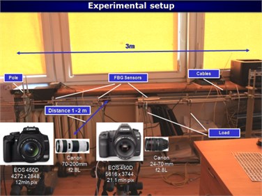
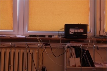
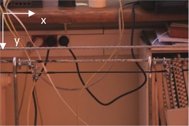
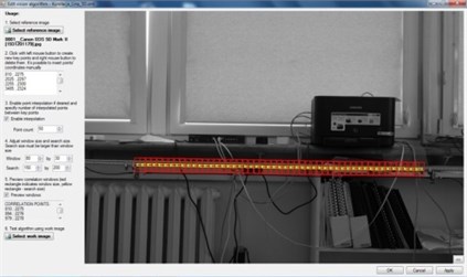
In the experiment, deflection of the transmission line cable under a changing load was measured. The surface of the cable was prepared by spraying a random intensity pattern used in DIC-based measurement. The cable was loaded by a set of weights hung in different positions along its length. Images of the analyzed object for different states of loading were acquired by two digital SLR Canon Cameras. The first camera was a Canon EOS 5D Mark II model with 5616×3744 resolution and a focal lens adjusted to 42 mm (Fig. 2b). The scale coefficient was computed as 0.275 mm/pix. Its field of view was wider and, therefore, the camera was used to obtain a deflection curve of the cable under the load of hanging weights. The cable was divided into 50 measurement points (Fig. 2d). The chosen size of the DIC pattern window was 80×30 pixels. To reduce the computational cost, each pattern was searched in a neighborhood of 150×200 pixels (Fig. 2d). The second camera was a Canon 450D model with a resolution of 4272×2848 and a lens with the focal length adjusted to 96 mm (Fig. 2c). The scale coefficient was equal to 0.13 mm/pix. The camera had a smaller field of view and was used to obtain high resolution measurement of the relative displacement of two markers placed on the cable. Markers were taken as pattern windows for the DIC algorithm. During the examination, the camera system acquired 30 images of the lab set-up for each of the loading conditions. The loading conditions were as follows: 1) no loading, 2) 2 weights hanging, 3) 4 weights hanging, 4) 6 weights hanging, 5) 4 weights hanging, 2 removed, 6) 2 weights hanging, 2 removed, 7) no weights hanging. The configuration of hung weights over the experiments is shown in Figure 2.
In the investigation, the displacement of each measurement point was calculated relative to the reference case. The deflection curve of a transmission cable under increasing load was obtained. Next, the maximum deflection of the deflection curve for each loading condition was computed and taken as the sag of the cable. The obtained values are presented in Table 1. An example of the deflection curve for Loading Condition 4 is shown in Figure 3. In the case of the second experiment, the displacement of two markers was computed. The values of changes in distance between two markers in the X and Y axes for each of the loading conditions are shown in Table 2.
Fig. 2Measurement of a cable deflection: a) the laboratory stand; b) the field of view of the Canon EOS 5D MII camera (with 42 mm focal length) used to the compute displacement field of the cable under the load; c) the field of view of the Canon 450D camera (with 96 mm focal length) used to compute the relative displacement between two Bragg sensors; d) image of the cable divided into a set of intensity patterns
a)
b)
c)
d)
Table 1Maximum displacement of the cable for each of the loading conditions. The scale coefficient of the camera was 0.275 mm/pix
Loading condition case | Value of maximum displacement |
1 | Reference case |
#2 (2 weights) | 5.35 mm |
#3 (4 weights) | 6.91 mm |
#4 (6 weights) | 9.42 mm |
#5 (4 weights) | 8.32 mm |
#6 (2 weights) | 5.40 mm |
#7 (no weights) | 0.03 mm |
The images of the unloaded cable were used to assess the level of the measurement noise of the vision system, computed as the standard deviation of the displacement of points on the reference image. This amounted to 0.03 mm (in the case of the first camera). The value of the noise in the case of the second camera was equal to 0.0037 mm for X displacement and 0.0049 mm for Y displacement.
Fig. 3Deflection curve obtained for #4 loading case (see Table 1)
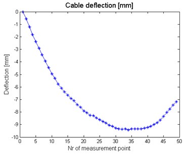
Table 2Relative displacement between two markers obtained by the second camera in the system. The scale coefficient of the camera was 0.13 mm/pix
Loading condition case | Relative X displacement | Relative Y displacement |
1 | Reference case | Reference case |
#2 (2 weights) | 0.16 mm | 0.42 mm |
#3 (4 weights) | 0.19 mm | 1.23 mm |
#4 (6 weights) | 0.23 mm | 1.79 mm |
#5 (4 weights) | 0.19 mm | 1.15 mm |
#6 (2 weights) | 0.14 mm | 0.42 mm |
#7 (no weights) | 0.01 mm | 0.015 mm |
3.2. Vision-based measurement of the cable’s vibrations
In the experiment, the vibrations of markers placed on the transmission line cable were investigated. The measurement was carried out by a stereo-vision system equipped with two high-speed digital cameras. The examined object was excited by random noise signals using an electrodynamic shaker. The lab setup consisted of the following elements:
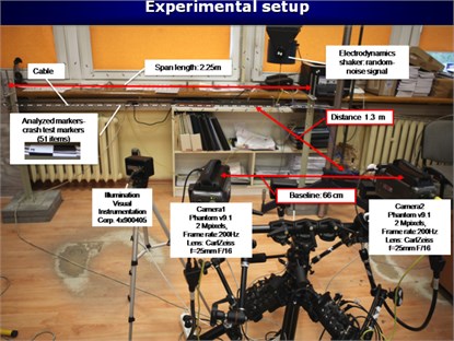
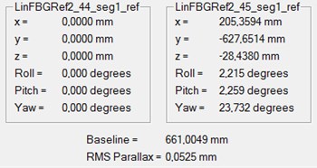
1) A stereo-vision system with two high-speed Phantom v9.1 cameras of a maximum resolution of 1632×1200, with a fixed focal length Carl Zeiss lens of = 25 mm. The system was placed on a stereo-vision head and mounted on a tripod at a distance of 1.3 m from the object. The baseline of the system was 661 mm. The relative position and orientation of the cameras was obtained in an external calibration. In order to obtain a frame rate of 200 Hz with a time of acquisition equal to 23.7 seconds, the region of interest of the image was decreased to 1632×800. The parameters of the cameras were set as follows: resolution: 1632×800, frame rate: 200, exposure time: 4000 μs, acquisition time: 23.7 seconds, Camera_1 No:9645 in the Master operating mode, Camera_2 No:9644 in the Slave mode. An electrodynamic shaker exciting the analyzed cable with a white noise signal. A laboratory setup consisting of a hung cable (length: 2.25 m) and a set of markers (51 crash test markers).
2) An electrodynamic shaker exciting the analyzed cable with a white noise signal.
3) A laboratory setup consisting of a hung cable (length: 2.25 m) and a set of markers (51 crash test markers).
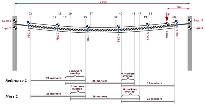
During the examination (Fig. 5), two measurement sessions were carried out, one referential case (Reference1) and one involving an extra mass (Mass1). In each measurement session, five measurement series were performed. The positions of markers on the lab setup are shown in Figure 5. To increase the spatial resolution of the vision system, motion analysis was conducted on three segments of the analyzed object (overhead line section stand). They correspond to the three smaller fields of view of the stereo-vision system, as demonstrated in Figure 5. Each measurement area (“small” field of view, sFOV) included 21, 26 and 19 crash-test markers, respectively. For example, at a distance of 1.3 m from the analyzed object, the sFOV of the stereo-system amounted to 880 mm
Fig. 4Laboratory stand for vibration measurement: a) overhead line section laboratory model and the stereo-vision system configuration and arrangement; b) external parameters of the stereo-vision system
a)
b)
Fig. 5Schematic layout of the measurement points (markers) on the test stand, the numbering and field of view of the stereo-vision system in various stages of the experiment. The point of the exciting force is indicated with a red arrow
The high-speed camera system’s data was recorded and stored in cine movie sequence files. Next, the data was loaded in TEMA Automotive software in order to extract the positions of each of the markers and track them across frames of the sequence. The tracking method chosen for a set of markers was Quadrant Symmetry [28, 29]. 3D trajectories of the markers were reconstructed based on the trajectories of corresponding markers on two image sequences captured by the stereo-vision system [28].
Regarding the conducted experiment, the measurement noise levels amounted to 0.0298, 0.0102 and 0.00921 mm, along the x, y and z axes, respectively. The noise was estimated as the mean value of standard derivation calculated over all the measurement points.
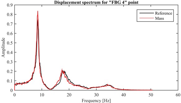
Data concerning the 3D trajectories for each of the movie sequences were exported to .xls files and then to the MATLAB programming environment, where the frequency response of the system was estimated. An example of the obtained frequency response plot calculated for the “FBG4” measurement point is presented in Figure 6. In the figure, a black line indicates the resulting displacement spectrum obtained from the reference measurement data, whilst the red line demonstrates the displacement spectrum when additional mass was added to the transmission line. Considering intervention to the structure by adding mass in the Fourier spectra, there is a visible short shift of the spectra to the left side.
Fig. 6Displacement spectrum for point: “FBG4”
4. Conclusions
The experimental examination proved that a vision system can be used for the measurement of a transmission line cable’s displacements. The developed tool obtains a deflection curve of the cable under an increasing load. The measurement can be taken at a user-specified number of points along the length of the cable chosen. The value of the cable’s sag is found at the point of maximum displacement. The different sets of lenses for SLR cameras provide variable fields of view and, therefore, the desirable accuracy of the obtained results. The second experiment revealed that the developed stereo-vision system equipped with high-speed cameras can be applied to analyze the dynamics of overhead transmission line cables. The recorded image sequences registered by two cameras of the stereo-vision system are used to reconstruct the 3D trajectories of chosen points on the cable. The amplitude of vibrations, as well as a set of a structure's natural frequencies, can be computed based on the acquired image data. The developed vision-based measurement system is accurate enough to distinguish changes in the dynamic behavior of the overhead transmission line model.
References
-
Malhara S., Vittal V. Mechanical state estimation of overhead transmission lines using tilt sensors. IEEE Transactions on Power Systems, Vol. 25, Issue 3, 2010, p. 1282-1230.
-
Seppa T. O. A practical approach for increasing the thermal capabilities of transmission lines. Power Delivery, Vol. 8, Issue 3, 1993, p. 1536-1550.
-
Rosiek M., Martowicz A., Uhl T. Electromechanical impedance based SHM system for aviation applications. Key Engineering Materials, Vol. 518, 2012, p. 127-136.
-
Manka M., Rosiek M., Martowicz A., Uhl T., Stepinski T. Properties of interdigital transducers for lamb-wave based SHM systems. Proceedings of the 8th International Workshop on Structural Health Monitoring, Stanford University, Stanford, CA, 2011.
-
Młyniec A., Ambrozinski Ł., Packo P., Bednarz J., Staszewski W. J., Uhl T. Adaptive de-icing system – numerical simulations and laboratory experimental validation. International Journal of Applied Electromagnetics and Mechanics, Vol. 46, Issue 4, 2014, p. 997-1008.
-
Burdzik R. Implementation of multidimensional identification of signal characteristics in the analysis of vibration properties of an automotive vehicle’s floor panel. Eksploatacja i Niezawodność – Maintenance and Reliability, Vol. 16, Issue 3, 2014, p. 439-445.
-
Jamro E., Wielgosz M., Bieniasz Slawomir B., Cioch W. FPGA-ARM heterogeneous system for high speed signal analysis. Solid State Phenomena, Vol. 180, 2012, p. 207-213.
-
Wei-Guo Tong, Bao-Shu Li, Jin-Sha Yuan, Shu-Tao Zhao Transmission line extraction and recognition from natural complex background. Proceedings of the Eighth International Conference On Machine Learning and Cybernetics, Baoding, 2009.
-
Sun Fengjie, Wang He, Fan Jieqing 2D Otsu segmentation algorithm based on simulated annealing genetic algorithm for iced-cable images. International Forum on Information Technology and Applications, Vol. 2, 2009, p. 600-602.
-
Sun Feng-jie, Tian Ye Transmission line image segmentation based GA and PSO hybrid algorithm. International Conference on Computational and Information Sciences, 2010, p. 677-680.
-
Yuqin Yao, Wenbin Wang, Feixiang Chen, Yuanpeng Yu Nondestructive testing of transmission lines based on the image method. International Conference on Electronics, Communications and Control, 2011, p. 2143-2146.
-
Jun Zhao, Shu-tao Zhao and Qi-neng Jiang Power transmission tower type determining method based on aerial image analysis. China International Conference on Electricity Distribution, 2010, p. 1-5.
-
Xiaopeng Wang, Jianlin Hu, Bin Wu, Lin Du, Caixin Sun Study on edge extraction methods for image-based icing on-line monitoring on overhead transmission lines. International Conference on High Voltage Engineering and Application, Chongqing, China, 2008.
-
Geng Xin, Hu Xiaoguang On-line monitoring method and observation system of transmission line icing. Proceeding of IEEE 4th Conference on Industrial Electronics and Applications, 2009, p. 1265-1269.
-
Chunsheng Yu, Qingjin Peng, Randy Wachal, Pei Wang An image-based 3D acquisition of ice accretions on power transmission lines. Canadian Conference on Electrical and Computer Engineering, 2006, p. 2005-2008.
-
Wachal R., Stoezel J., Peckover M., Godkin D. A computer vision early-warning ice detection system for the smart grid. Transmission and Distribution Conference and Exposition, 2012, p. 1-6.
-
Alberto Vallan, Filippo Molinari Image analysis of metallic ropes for the measurement of the lay length. IEEE International Conference on Instrumentation and Measurement Technology, Victoria, Vancouver Island, Canada, 2008
-
Ishino R., Tsutsumi F. Detection system of damaged cables using video obtained from an aerial inspection of transmission lines. Power Engineering Society General Meeting, Vol. 2, 2004, p. 1857-1862.
-
Busca G., Cigada A., Manenti A., Zappa E. Vision-based measurements for slender structures vibration monitoring. IEEE Workshop on Environmental, Energy, and Structural Monitoring Systems, EESMS, 2009, p. 98-102.
-
Byeong Hwa Kim Extracting modal parameters of a cable on shaky motion pictures. Mechanical Systems and Signal Processing, Vol. 49, Issues 1-2, 2014, p. 3-12.
-
Xiaobo Meng, Lei Hou, Liming Wanga, Mark MacAlpine, Guanjun Fu, Baoqiang Sun, ZhichengGuan, Wei Hud, Yong Chen Oscillation of conductors following ice-shedding on UHV transmission lines. Mechanical Systems and Signal Processing, Vol. 30, 2012, p. 393-406.
-
Kohut P., Kurowski P. Application of vision for modal experiment. Machine Dynamics Problems, Vol. 29, Issue 2, 2005, p. 81-90.
-
Kohut P., Kurowski P. The integration of vision system and modal analysis for SHM application. A Conference and Exposition on Structural Dynamics, IMAC 24, 2006.
-
Kohut P., Kurowski P. The 3D vision-based measurements for modal analysis. 3rd Workshop on Optical and Measurement Techniques for Structures and Systems, Proceedings of OPTIMESS, Belgium, Leuven, 2007.
-
Sung-Wan Kim, Nam-Sik Kim Dynamic characteristics of suspension bridge hanger cables using digital image processing. NDT&E International, Vol. 59, 2013, p. 25-33.
-
Kohut P., Gaska A., Holak K., Ostrowska K., Sładek J., Uhl T., Dworakowski Z. A structure’s deflection measurement and monitoring system supported by a vision system. Technisches Messen, Vol. 81, Issue 12, 2014, p. 635-643.
-
Kohut P., Holak K., Mączak J., Szulim P., Uhl T. Application of vision based damage detection for real civil engineering structure. Key Engineering Materials, Vol. 588, 2014, p. 22-32.
-
TEMA User’s Guide. Image Systems AB, 2011
-
Kohut P., Kurc K., Szybicki D., Cioch W., Burdzik R. Vision-based motion analysis and deflection measurement of a robot’s crawler unit. Journal of Vibroengineering, Vol. 1, Issue 8, 2015, p. 4112-4121.
-
Młyńczak J. Algorithm Determining the Setting Force at Point Machines. Telematics – Support for Transport, Book Series: Communications in Computer and Information Science 471, Springer, Heidelberg, 2014, p. 321-330.
About this article
Reported research realized within confines of the Project GEKON 1/02/214108/19/2014: “Dynamic Management of the Transmission Capacity of Power Lines Using Innovative Measurement Techniques”.

