Abstract
U-shape nanoelectromechanical systems (NEMS) are potential for developing miniature sensors. While the electro-mechanical performance of conventional beam-type NEMS has been exclusively addressed in the literature, few works have considered this phenomenon in U-shaped systems. Herein, the static and dynamic pull-in instability of the U-shaped NEMS is investigated under the presence of vdW force. Based on the recently developed consistent couple stress theory (CCST), the size-dependent constitutive equation is derived. Two types of the beam cross-sections including rectangular and circular geometries are considered. The nonlinear equations are solved by employing Ray-leigh-Ritz solution method. The developed model is validated by comparison with the results presented in literature. The effect of various parameters on the static and dynamic pull-in parameters, phase plans and stability threshold of the system is discussed. The obtained results reveal that the vdW attraction decreases the pull-in voltage while the size dependency enhances the instability voltage. On the other hand, the presented model demonstrates that characteristics of the tip-plate can change the pull-in parameters significantly.
1. Introduction
A true understanding of the electromechanical stable behavior of NEMS is crucial for reliable design, fabrication and operation of these devices. Many investigators have studied the mechanical characteristics of these miniature structures [1-4]. The pull-in instability of conventional NEMS with simple beam-type electrode is studied in many articles [4-6]. It can be seen that few articles analyzed pull-in instability of U-shaped NEMS. In this regard, the present work is devoted to study of the pull-in behavior of the U-shaped NEMS. The U-shaped NEMS are made of two parallel cantilever micro/nano-beams with a rigid plate attached to theirs free ends. The U-shaped MEMS/NEMS are used for developing new generation of miniature sensors, actuators and switches [7-10]. Qian et al. applied a U-shaped NEMS consist of a capacitive rigid plate supported by two silicon nanowires. Thay proved repeatable switching behavior and low actuation voltage for U-shaped NEMS [9]. The U-shaped actuator for capacitive applications with adjustable tuning range is studied by Yan and coworkers [8]. They showed that U-shaped structures provide enhanced electrical performance. They showed that the U-shaped structures provide enhanced electrical performance. Koukharenko et al. applied ANSYS software and surveyed the mechanical characteristics of the silicon U-shaped micro-generator [10].
In order to precise modeling of the mentioned nanostructures, incorporation of the nano-scale phenomena such as van der Waals (vdW) force is crucial. It is well proved that the presence of vdW force substantially affects the pull-in instability of NEMS at the nano-scale separations. Many researchers have been demonstrated the impact of vdW force on adhesion and stability characteristics of ultra-small devices [11-13]. Experiments show a hardening trend in elastic response of some materials such as conductive metals as the dimensions approaches to the material length scale [14, 15]. This size-dependency of material characteristics, i.e. size effect, cannot be modeled via classic continuum mechanics. In order to overcome this shortcoming, the non-classical theories such as non-local elasticity [16], couple-stress theory [17], strain gradient theory [14], modified couple-stress theory [18], consistent couple stress theory (CCST) [19] etc. have been applied to consider the size effect in theoretical continuum models.
To the best knowledge of the authors, the electromechanical performance of U-shaped structures in the vdW regime has not been addressed yet. Herein, the effect of vdW force is incorporated in theoretical modeling of the U-shaped NEMS. Besides the vdW force, the size effect is another crucial small-scale phenomenon that might affect the performance of NEMS, hence should be incorporated in theoretical models. The equivalent boundary condition technique is applied to obtain the governing equation. The size dependency of material is modeled based on recently developed non-classical theory i.e. CCST in conjunction with the Euler-Bernoulli beam model. Two different cross sections (i.e. rectangle and circle) are simulated using the proposed model. The Rayleigh-Ritz method (RRM) is applied to solve the obtained equations.
2. Theory
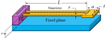
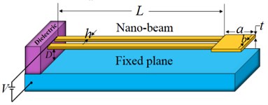
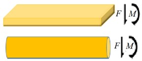
Figs. 1(a) and 1(b) depict the schematic diagram of typical U-shaped element fabricated from two cantilever nanobeam or nanowire -depending on the fabrication method- attached to a rigid plate. The DC voltage difference and initial gap between the U-shaped element and the plane are and , respectively. For beam-made device the length of , width of and thickness of is considered. For wire-made device the length of and radius of is considered. The free-body diagram of the beam/wire cross-section is shown in Fig. 1(c) that and denote the force and moment at the non-supported end of the nanobeam/wire (), respectively.
Fig. 1The schematic representation of a) U-shaped NEMS made of nanobeam, b) U-shaped NEMS made of nanowire, c) internal resultants in arbitrary cross-section
a)
b)
c)
Based on the CCST, the strain energy () can be explained as [19]:
The strain tensor () and stress tensor () can explain as:
where and are the Lame’s constants and is the displacement field. The curvature tensor () and the couple-stress tensor () are defined as:
where is the material length scale parameter. For an Euler-Bernoulli beam/wire, the displacement field can be expressed as [20]:
where is the centerline deflection of the beam/wire in the direction and , and are the displacement components in the , and directions, respectively. Considering small deformation, and substituting relations Eq. (6) in Eqs. (2-5) one obtains:
By substituting Eq. (7) in Eq. (1) after some elaboration and integrating over the beam/wire volume, the bending strain energy is obtained as the following:
For each beam/wire element, the work done by external forces, , can be determined as:
where the external forces, , is the summation of the electrostatic and vdW forces per unit length of the beam/wire.
Based on capacitive model, the electrical attraction per unit length of the beam, , in the case of nanobeam is expressed as [21, 22]:
where , , , , and are the permittivity of vacuum, dielectric constant, the beam width, the gap distance, and applied voltage, respectively. Also, the vdW attraction per unit length of the beam, , is derived as [23]:
where , , and , are the Hamaker constant, the beam width, and the gap distance, respectively. Similarly, for the U-shaped element made of nanowire (Fig. (1b)), the electrostatic force terms in relation Eq. (9) can be determined from the capacitive model as the following [23]:
where is radius of the nanowire. Also, the vdW attraction between a cylinder and flat plane can be evaluated as [24]:
For the U-shaped system, the stress resultants are induced by the electrostatic and vdW attractions between the rigid plate and the ground. The work done by the moment traction, , is obtained as:
The work done by the force traction, , is determined as:
In Eqs. (14) and (15), the force () and moment () are the summation of the force and moment due to electrostatic and vdW forces which are calculated by integrating over the rigid plate area which consided as a typical rigid plate with the length and width . The electrostatic and vdW forces and moments can be determined as:
It should be noted that half of the forces and momentum resultants should be considered as the contribution of each wire/beam. The kinetic energy of the beam and tip plate can be expressed as:
and finally the virtual work performed by damping effects can be expressed as:
where is the damping coefficient. The total energy of system can be summarized as:
Now, by substituting Eqs. (10)-(13) and (16)-(20) in Eq. (21) and some mathematical elaboration the dimensionless total energy can be explained as:
For nanobeam-made sensor and:
For nanobeam-made sensor. In Eqs. (22), the dimensionless parameters are defined as:
3. Solving methods
In this section, the Rayleigh-Ritz method in conjunction with the total energy of the system (Eq. (22)) are employed to obtain the deflection of the beam/wire. The displacement is expressed as a combination of a complete set of independent basis functions in the form of:
where the index refers to the number of modes included in the simulation. We use the linear mode shapes of the cantilever nanobeam (based on the classic continuum theory) as basic functions in the Rayleigh-Ritz procedure:
where is the throot of characteristic equation of the cantilever beams in the classical theory. For minimize the total energy of the system we must have:
This leads to a system of time-dependent equations which can be solved numerically. Substituting Eqs. (23) and (24) into Eq. (26), assuming the orthogonality of and then following some straightforward mathematical operations, a system of governing equations can be fined as:
For nanobeam-made sensor and:
For nanowire-made sensor. In Eq. (27) we have:
Finally, the MAPLE commercial
software is used to numerically solve the system of equations.
4. Results and discussion
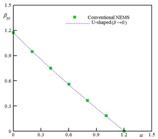
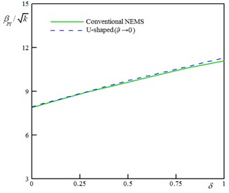
The asymptotic cases (→ 0) of the U-shaped NEMS are compared with that of conventional systems (a cantilever nanobeam suspended over a ground plane) studied in Refs. [25, 26]. Fig. 2(a) shows the variation of the instability voltage of the nanobeam versus the parameter for the conventional [25] and the asymptotic U-shaped (→ 0) systems. Also, Fig. 2(b) shows the variation of pull-in voltage of the nanowire versus the size effect parameter [26]. As shown, if → 0 the results of the presented model approaches to those of conventional systems.
Furthermore, the accuracy of the present model is examined by comparing the obtained theoretical results with the experiment and COMSOL simulation reported in the literature [9]. Qian et al. studied the instability voltage of the U-type switches made of silicon-nanobeams with 2 μm length and 4 μm width supported by two silicon nanobeams with 5 μm length. This U-shaped structure suspended on top of the substrate with a gap of 145 nm. A comparison between our model and those of experiments and COMSOL simulation is summarized in table 1. It can be seen an acceptable agreement between the proposed model and those of experiments and simulation.
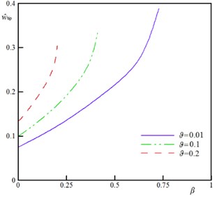
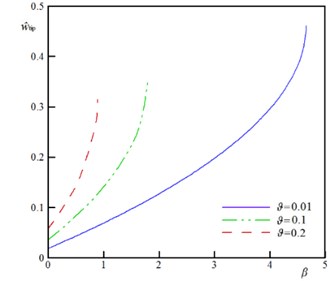
Fig. 3 shows the variation of the beam/wire tip displacement () versus the dimensionless voltage () for different values of parameter . As seen, for any applied voltage, where , one can find a solution for . On the other hand, when , no solution exists for . This implies the occurrence of the instability and the beam/wire adheres to the fixed plane. At the instability threshold, the slope of the curves approaches to infinity ( → ∞) that implies the feasibility of further increase in the beam/wire deflection even in the absence of electrical/ force(s). Also, Fig. 3 demonstrates that enhancing the parameter decreases the maximum tip displacement () of the sensors.
Table 1Pull-in voltage comparison between the proposed solutions and experimental reports [9]. (E= 202 GPa and l= 2 nm)
Case | Experiment [9] | COMSOL [9] | RRM |
Pull-in voltage (V) | 1.12 | 1.04 | 1.03 |
Error (%) | – | 7.1 | 8.0 |
Fig. 2Comparison between the conventional and the asymptotic U-shaped (ϑ → 0) systems; a) variation of the pull-in voltage of nanobeam vs. vdW parameter (D/h= 1.0, and δ= 0), b) effect of the size dependency on the pull-in characteristics of nanowire (D/r= 100, and α= 0)
a)
b)
Fig. 3The w^tip versus β for various values of ϑ (k= 0.5, ξ= 0.2, τ= 0.02, α= 0.5, Ω= 0.5, and δ= 0)
a) Nanobeam
b) Nanowire
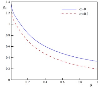
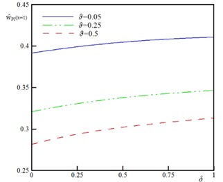
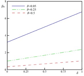
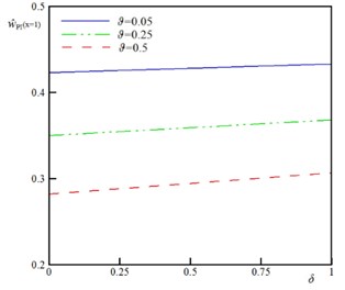
To demonstrate the impact of the rigid plate geometry on the stability of the sensor, the variation of the instability characteristics as a function of the geometrical parameter for various vdW parameter () is plotted in Fig. 4. The dimensionless parameter represents the ratio between rigid plate surface area and beams/wires surface area. By increasing , the pull-in voltage () and pull-in deflection () decrease. This implies that increase in the rigid plate surface increases the external forces and reduces the stability threshold of the sensor. Furthermore, the and approach to an asymptotic value by decrease in value. These asymptotic values equal to and of conventional sensor (without rigid plate). Fig. 5 illustrates the impact of the size dependency on the pull-in of the sensor. The zero value of corresponds to the classic continuum theory i.e. the beam diameter is highly larger than the intrinsic material length scale (). According to the results of this figure, increase in the size parameter () enhances the instability characteristics of the actuator. Furthermore, this figure shows that the impact of size phenomenon on the instability of the U-shaped is more pronounced for higher values of (large rigid plates).
Fig. 4The variation of the pull-in characteristics versus ϑ for different values of α (k= 0.5, ξ= 0.2, τ= 0.02, Ω= 0.5, and δ= 0)
a) Nanobeam,
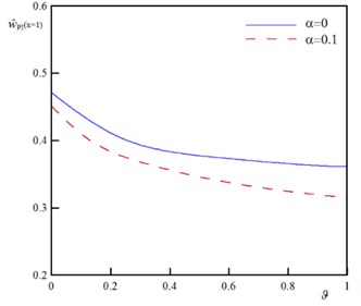
b) Nanobeam,
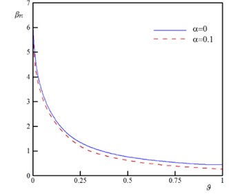
c) Nanowire,
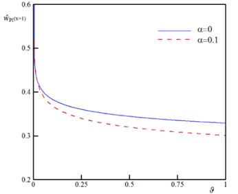
d) Nanowire,
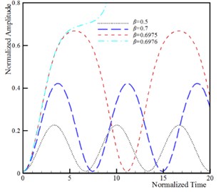
The dynamic pull-in corresponds to the influence of the beam inertia on the instability threshold of the system. It is well-known that the dynamic instability threshold is lower than the static instability threshold due to the presence of the inertia effect. The time history and phase plane of the U-shaped nanostructures for various applied voltages is shown in Fig. 6. This figure reveals that maximum amplitude of the beam/wire tip deflection increases by increasing the DC voltage. When the applied voltage exceeds its critical value, , then the tip deflection increase rapidly and instability occurs. Fig. 6 reveals that the phase plane has two fixed points; the stable center point and the unstable saddle node. The homoclinic orbit originates from the unstable branch saddle node and returns to it with the stable one. Beyond the unstable saddle node, the beam/wire collapses to fixed plane and become structurally unstable. The influence of the damping on the dynamic behavior of vibrating nanoactuators is illustrated in Fig. 7. The obtained results show that the stable center equilibrium point becomes a stable focus point when the damping parameter is taken into account. It can be concluded that the beam/wire makes convergent oscillations near the focus point because of the damping, and makes periodic oscillations if the damping is neglected. On the other hand, the second equilibrium point is unstable saddle point for any values of damping parameter. When the actuation voltage reaches the pull-in voltage, the trajectories which are attracted to the stable focus due to the damping effect, diverge and system becomes unstable.
Fig. 5The variation of the βPI and w^PIx=1 versus δ for different values of ϑ (k= 0.5, ξ= 1.0, τ= 0.1, Ω= 0.5, and α= 0.25)
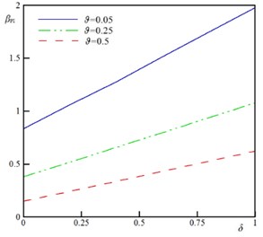
a) Nanobeam,
b) Nanobeam,
c) Nanowire,
d) Nanowire,
Fig. 6Dynamic behavior of system (k= 5, ξ= 0.5, τ= 0.25, ϑ= 0.25, α= 0.1 and δ= 0.1)
a) Time history of beam
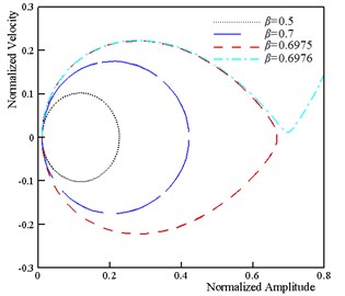
b) Phase plane of beam
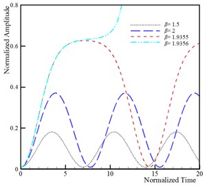
c) Time history of wire
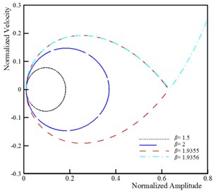
d) Phase plane of wire
Fig. 7Influence of damping parameter on the dynamic behavior of system (k= 5, ξ= 0.5, τ= 0.25, ϑ= 0.25, α= 0.1 and δ=0.1)
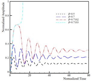
a) Time history of beam
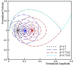
b) Phase plane of beam
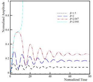
c) Time history of wire
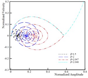
d) Phase plane of wire
5. Conclusions
In this research, the CCST was applied for modeling the size-dependent pull-in instability of U-shaped sensors in the vdW regime. A general continuum model was developed and the governing equation was derived and solved using Rayleigh-Ritz method. It is found that the vdW attraction decreases while the size effect increases the pull-in voltage of the sensors. The pull-in characteristics and the critical value of vdW force was significantly affected by geometrical characteristics of the tip-plate. The good agreement between the present model and those in literature corroborated the reliability of the present approach. The U-shaped sensors showed convergent oscillations near the focus point in the presence of damping and periodic oscillations in the absence of damping. The obtained results are beneficial to design and fabrication of U-shaped systems.
References
-
Keivani M., Khorsandi J., Mokhtari J., Kanani A., Abadian N., Abadyan M. Pull-in instability of paddle-type and double-sided NEMS sensors under the accelerating force. Acta Astronautica, Vol. 119, Issue 1, 2016, p. 196-206.
-
Wang Q. X., Li H., Lam K. Y. Analysis of microelectromechanical systems (MEMS) devices by the meshless point weighted least-squares method. Computational Mechanics, Vol. 40, Issue 1, 2007, p. 1-11.
-
Keivani M., Kanani A., Mardaneh M. R., Mokhtari J., Abadyan N., Abadyan M. Influence of accelerating force on the electromechanical instability of paddle-type and double-sided sensors made of nanowires. International Journal of Applied Mechanics, Vol. 8, Issue 1, 2016, p. 1650011.
-
Farrokhabadi A., Mokhtari J., Rach R., Abadyan M. Modeling the influence of the Casimir force on the pull-in instability of nanowire-fabricated nanotweezers. International Journal of Modern Physics B, Vol. 29, Issue 2, 2015, p. 1450245.
-
Keivani M., Mokhtari J., Abadian N., Abbasi M., Koochi A., Abadyan M. Analysis of U-shaped NEMS in the Presence of Electrostatic, Casimir, and Centrifugal Forces Using Consistent Couple Stress Theory. Iranian Journal of Science and Technology, 2017, (in Press).
-
Farrokhabadi A., Mokhtari J., Koochi A., Abadyan M. A theoretical model for investigating the effect of vacuum fluctuations on the electromechanical stability of nanotweezers. Indian Journal of Physics, Vol. 89, Issue 6, 2015, p. 599-609.
-
Keivani M., Gheisari R., Kanani A., et al. Effect of the centrifugal force on the electromechanical instability of U-shaped and double-sided sensors made of cylindrical nanowires. Journal of the Brazilian Society of Mechanical Sciences and Engineering, Vol. 38, Issue 7, 2016, p. 2129-2148.
-
Yan D., Khajepour A., Mansour R. Design and modeling of a MEMS bidirectional vertical thermal actuator. Journal of Micromechanics and Microengineering, Vol. 14, Issue 7, 2004, p. 841.
-
Qian Y., Lou L., Tsai M. J., Lee C. A dual-silicon-nanowires based U-shape nanoelectromechanical switch with low pull-in voltage. Applied Physics Letters, Vol. 100, Issue 11, 2012, p. 113102.
-
Koukharenko E., Beeby S. P., Tudor M. J., White N. M., O’Donnell T., Saha C., Kulkarni S., Roy S. Microelectromechanical systems vibration powered electromagnetic generator for wireless sensor applications. Microsystem Technologies, Vol. 12, Issue 10, 2006, p. 1071-1077.
-
Keivani M., Mokhtari J., Kanani A., Abadian N., Rach R., Abadyan M. A size-dependent model for instability analysis of paddle-type and double-sided NEMS measurement sensors in the presence of centrifugal force. Mechanics of Advanced Materials and Structures, Vol. 24, Issue 10, 2017, p. 809-819.
-
Abdi J., Koochi A., Kazemi A. S., Abadyan M. Modeling the effects of size dependence and dispersion forces on the pull-in instability of electrostatic cantilever NEMS using modified couple stress theory. Smart Materials and Structures, Vol. 20, Issue 5, 2011, p. 055011.
-
Wang G. W., Zhang Y., Zhao Y. P., Yang G. T. Pull-in instability study of carbon nanotube tweezers under the influence of van der Waals forces. Journal of Micromechanics and Microengineering, Vol. 14, Issue 8, 2004, p. 1119.
-
Lam D. C., Yang F., Chong A. C., Wang J., Tong P. Experiments and theory in strain gradient elasticity. Journal of the Mechanics and Physics of Solids, Vol. 51, Issue 8, 2003, p. 1477-1508.
-
McFarland A. W., Colton J. S. Role of material microstructure in plate stiffness with relevance to microcantilever sensors. Journal of Micromechanics and Microengineering, Vol. 15, Issue 5, 2005, p. 1060.
-
Eringen A. C., Edelen D. G. On nonlocal elasticity. International Journal of Engineering Science, Vol. 10, Issue 3, 1972, p. 233-248.
-
Ejike U. B. The plane circular crack problem in the linearized couple-stress theory. International Journal of Engineering Science, Vol. 7, Issue 9, 1969, p. 947-961.
-
Yang F. A., Chong A. C., Lam D. C., Tong P. Couple stress based strain gradient theory for elasticity. International Journal of Solids and Structures, Vol. 39, Issue 10, 2002, p. 2731-2743.
-
Keivani M., Koochi A., Abadyan M. A new model for stability analysis of electromechanical nano-actuator based on Gurtin-Murdoch and consistent couple-stress theories. Journal of Vibroengineering, Vol. 18, Issue 3, 2016, p. 1406-1416.
-
Dym C. L., Shames I. H. Solid Mechanics: A Variational Approach. Railway Publishing House, Beijing, China, 1984.
-
Jackson J. D. Classical Electrodynamics. Wiley, 1999.
-
Gupta R. K. Electrostatic Pull-In Test Structure Design for in Situ Mechanical Property Measurements of Microelectromechanical Systems. Ph.D. Dissertation Massachusetts Institute of Technology (MIT), Cambridge, MA, 1997.
-
Hayt W. H. Engineering Electromagnetics. McGraw-Hill, New York, 1981.
-
Israelachvili J. N. Intermolecular and Surface Forces. Third Edition, Academic Press, 2011.
-
Soroush R., Koochi A., Kazemi A. S., Noghrehabadi A., Haddadpour H., Abadyan M. Investigating the effect of Casimir and van der Waals attractions on the electrostatic pull-in instability of nano-actuators. Physica Scripta, Vol. 82, 4, p. 2010-45801.
-
Koochi A., Farrokhabadi A., Abadyan M. Modeling the size dependent instability of NEMS sensor/actuator made of nano-wire with circular cross-section. Microsystem Technologies, Vol. 21, Issue 2, 2015, p. 355-364.
About this article
This paper has been done on the supervision of N. Abadian. The paper has been wrote by A. Koochi and N. Abadian. M. Abadyan and E. Ghahremani have developed the mechanical and mathematical models for considering the size dependency. J. Mokhtari has developed the physical model for considering vdW and electrical forces. J. Mokhtari and A. Koochi solved the nonlinear governing equation and plot the figures. The paper has been revised by M. Keivani and E. Ghahremani.
