Abstract
The essential phenomenon accompanying hoisting machines such as overhead cranes is the occurring of negative vibrations. Due to the characteristic beam type construction of the load carrying structure, they were particularly important in the case of heavy loads, causing considerable stress values, both in the ropes and girder structure. These values are described by dynamic coefficient examined in this study. Because of the problem importance, a different approach to modeling the process of lifting the load is proposed, mainly due to the dynamic model of rope applied. It proposes models of the rope and lifting mechanism, using both the modified Bouc-Wen model as well as a classical model of Kelvin-Voigt as a model of rope in the hoisting mechanism, where the value of dynamic factor has been verified. It helps to specify the multiplicity of overloading the structure and impact of rope modeling method according to its value. The models for the test of hoisting machines proposed in the paper include the modeling of the wire rope in the hoisting mechanism and the influence of ropes modeling method on a dynamic factor.
1. Introduction
Machinery and transport equipment allow to performed tasks related to transport of people or goods. That machinery includes cranes, especially overhead ones. The main task of lifting mechanism is to lift cargo with a specific weight with a predetermined speed to the designated height while maintaining the assumed acceleration values. For the rational selection of the drive system components, such as motor or brake, and above all to carry out strength calculations [1], the maximal and the statistically most frequent loads of these elements must be specified. They occur during the crane work in interval operation, which means that the subsequent transfer of cargo takes place intermittently needed to perform the handling work, such as the “engagement” or “detach” of cargo. Defining loads of assembly parts is carried out by differential equations of motion for specific cases of crane work, i.e. for a start-up phase, steady movement and braking. At steady state, all the energy supplied by the motor will be consumed to overcome the resistance movement, whereas the kinetic energy of the moving parts of the system at this time is not changed. For the transient phase of motion, there is an additional stream of dynamic power in the system (caused by changes in kinetic energy of the moving components), leading to increases loads acting on the system. Since every real object has a certain deformability of ties combining the moving masses, any change causes vibrations, the result of which is a dynamic factor. One of the most important elements of a hoisting mechanism of overhead cranes is the rope. Wire rope as an intermediary between the load and the support structure is most vulnerable to damage. Reducing its strength has an impact on the safety of both people and cargo. In the ropes, both at the micro and macro, mechanical phenomena occur are hard to be interpreted in the form of a mathematical description. These difficulties are associated among other things with the phenomenon of the contact point or continuous strands on the core and the internal friction. It generates problems of estimating the physical parameters. Depending on the rope load-wear index and its construction, its mechanical properties are constantly changing (the new the rope, pre-loaded, worn) [2-4]. The complex internal structure of rope makes the numerical models [5-8] designed with a large simplification. Most frequently only its elastic properties are mapped, and assuming a linear characteristic.
The biggest problem in carrying out the simulation of the hoisting equipment, whose structure, and type of excitations has a very complex character, is a mathematical description of coupling between an electrical and mechanical system. Therefore, in simulations, it is often used a simplification of a model, where there is a lack of feedback between these systems. It is related to difficulties in calculations, hence the need to achieve a compromise between the model complexity and accuracy. A phenomenological model of hoisting mechanism drive, with high, accuracy reflects the behavior of the actual object, should consider subsystems with different technical nature, i.e., take into account the coupling between the electrical and mechanical systems [9-13]. Rope, which is the element connecting the drive system with the cargo, takes the main load values associated with the lifted load, and it is, therefore, vulnerable to destruction. In the case of improper use, the stress in the ropes is many times larger than the predicted values. Various attempts of the mathematical description of steel ropes were made, using elastic or elastic-damping elements or by using the finite element method, but in a limited range [14-16]. The biggest problem in the numerical description of the mechanical properties of the rope is to estimation the physical parameters, such as stiffness and the associated modulus of elasticity and damping. Moreover, the challenge is the modeling of the rope by using FEM, only a short parts of ropes were modeled, due to its complicated construction and the number of fields of contact between the wires and strands and the type of core used. Examples of works are shown in [17-19]. No model of rope in terms of FEM prevents the evaluation of stress distribution in rope in the hoisting process, at least in terms of the complex approach. Some attempts have been taken, e.g. At paper [20], where discretization the rope is made, for subsequent finite elements. Each elementary section during longitudinal vibrations is faced with visco-elastic interactions of adjacent elements. This approach yielded good results, but without the possibility of observation of the state of stress in the tendons, namely their distribution in the individual layers of the cross section.
Work concerning the dynamics of overhead cranes is mainly related to the impact of the way of modeling the hoisting mechanism as a whole, at the rate of a dynamic factor. They often do not take into account the impact of control and drive components, while the motion is induced mostly step extortion, what causes, that the resulting dynamic factor values, appear to be much larger than it and sometimes are also unverified studies on a real object. In [21] the analysis of the bridge crane, with a capacity of 50 kN was done, while lifting the load, wherein the supporting structure constitutes the truss girder. It has been paid much attention to a relatively accurate representation of the hoisting mechanism – especially the drive system. Includes an initial clearance between the hook and the load, equivalent to raising the ground (rope pre-loosening). In this perspective, dynamic factor value achieves significant value. Different approach presents work [8], where a vibration analysis of the intermittent moving load was made. Two models were developed: three mass and five mass system, including vibration isolation of the operator's seat. The results of numerical calculations were confirmed by tests on a real object. Good compatibility simulation with experimental tests was achieved despite a significant simplification of the hoisting mechanism in particular bottom pulley block. In paper [22] was carried out simulations of the dynamics of lifting load using Matlab-Simulink and FEA environment.
To carry out such simulations, it was necessary to use hybrid calculations, where system response generated by solving the equations of motion in Matlab-Simulink, was used to stimulate supporting constitution of the crane, during simulation in FEM. A different approach to the problem was presented in [23], where attempts were made to identify the coefficient of dynamic surpluses, caused by lifting a load of the round. In computer simulations, the relationship between load-carrying crane structure number of degrees of freedom and the value of surplus dynamic was exanimated. The studies included changing the stiffness and damping bands rope during its shortening. In this paper, particular emphasis is made on the determination of the dynamic factor for many constructions of cranes. A phenomenological model of the hoisting system was formulated, wherein the arrangement of pulleys is reduced to a single element of elastic damping, taking into account the non-linear stiffness and damping of rope. In the performed simulations it was assumed, that pick up a load from the ground occurs when achieving the nominal speed of the motor. Article [24] presents a particular approach to the electric part of the hoisting mechanism and the associated algorithm for controlling the drive inverters. In the end, giving satisfactory results as to the reduction of the dynamic forces by signals related to the angular velocity of the motor shaft or measuring the force on the equalizing disc, which is confirmed by the results of tests on a real object. At work [25] a dynamic model was presented of a hoisting mechanism including consideration of the impact and maintain the electrical section. The model takes into account the steel structure, mechanism, drive motors, drive systems. A crane was taken into consideration, where during the lifting process, two cases of induction motors control were considered. This approach allows for complex research a model in terms of its dynamics.
In this paper, an approach designed to address the problem of selection of the problematic parameters of wire rope, such as stiffness and damping with using a number of parameters were presented. They are obtained by the experiment giving it the opportunity to reflect hysteresis character. Thus, in this study, the main problem is put on the dynamic model of hoisting mechanism with a particular focus on a rope, where is proposed to use the Bouc-Wen model in a modified version, comparing it to the classical Kelvin-Voigt model for identified parameters obtained by the experiment. The aim of the research is to develop a new numerical model of crane lifting mechanism, as well as the selection and implementation of suitably modified Bouc-Wen model to match the numerical model of the wire rope mechanical and rheological properties. To achieve the intended objectives, wire rope model and procedures for effective parameter estimation for a Bouc-Wen model were implemented and presented in paper [26].
1.1. Research object
In this article, the subject of research is the overhead crane with a lifting capacity of 5000 kg and girder span of 20 m. Examined crane (Fig. 1) is a one girder construction and includes a trolley with two wheels, supported on the girder structure through an arm equipped with rollers moving along the side edge of the girder.
Table 1 presents the general characteristics of the examined crane. Presented data are obtained on the basis of technical documentation.
Fig. 1Experimental research crane – Research and Development Centre of Cranes Transport and Equipment “Detrans” in Bytom, movable winch, arm of the guide rollers
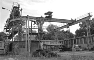
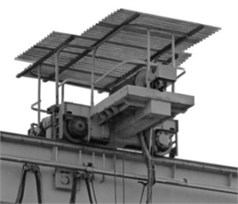
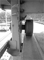
Table 1Overhead crane characteristics
Lifting capacity | Q | [kg] | 5000 | |
Span | Lmostu | [m] | 20 | |
Lifting height | Hpmax | [m] | 16 | |
Operating speeds | Lifting | vp | [m/s] | 0.208 |
Winches driving | vjw | [m/s] | 0.625 | |
Bridge driving | vjm | [m/s] | 0.472 | |
The drive system of tested lifting mechanism includes a slip ring asynchronous motor with a power of 10 kW. The system of ropes is a typical solution for cranes with a doubled system of pulleys and total ratio 2. Hoist mechanism used in the considered crane is described by coefficients presented in Table 2.
Table 2Lifting mechanism characteristics
Motor shaft with one end | Type | SZUDe | 56b | |
Pzn | [W] | 10e3 | ||
nzn | [rev./min] | 945 | ||
Gear ratio | ip | [–] | 10×6 = 60 | |
Diameter of drum | Db | [m] | 0.5 | |
Wire rope | Construction | SEALE 6x19 +FC sZ | ||
Diameter | dl | [m] | 0.012 | |
Number of bands | nlin | [–] | 4 | |
Rotation of drum | nb | [rev./min] | ~15.8 | |
1.2. Phenomenological models of ropes
The subject of this article is to study the relation between the wire rope model in a lift mechanism and a dynamic surplus factor. The indirect object of the research is, therefore, a hoisting wire rope. In this case, it is a steel wire rope with fiber core, and construction 6×19 SEALE +FC Zs and a diameter of 12 mm.
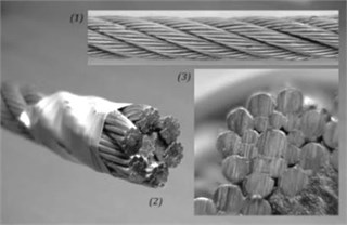
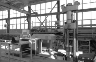
Even in the case of mechanical properties of wire rope in the model implementation attempt, it is necessary to perform series of studies, this kind of research rely on cyclic loading and unloading of selected wire rope. Under the terms of tensile tests of ropes included in the standard PN-EN ISO 6892-1: 2010 [27] series of tests of selected steel wire rope were done, as was described in the author publications. Fig. 2 presents the test object and the testing machine on which the experiment was performed.
Fig. 2Research object: 1) section of tested wire rope, 2) section, 3) strand construction; testing machine
As is evident from the conducted research and own analysis of literature [2-4, 28], at subsequent cycles of loading-unloading curves, showing the effect of hysteresis occurring in wire ropes are created. Both the curves of the load and the unload have non-linear shape, even after several cycles of loading and unloading. Obtained characteristic points, that the steel wire ropes have the characteristics of viscoelastic body and elastic-plastic. During each cycle of loading and unloading, there appears energy dissipation of strain, which is a measure of hysteresis loops. Therefore, it is reasonable to use phenomenological models, which give the opportunity to reflect these parameters. The first model of the wire rope is a classic model of Kelvin-Voigt, in which case, it's hard to determine the stiffness of the rope because of the Young's modulus, and the damping associated with friction between the wires and the strands and especially the fiber core. In the case of modeling the stiffness of the rope, it is possible to use simplification widely utilized in the literature, which is 50 % of Young’s modulus for steel ropes. Modulus of elasticity of the ropes described by discussed relation should be utilized for ropes containing fiber cores. In the case of steel wire ropes with a steel core should be used for purposes of computing the value of a module similar to the Young’s modulus of the material from which the rope was made [4].
The second proposed model is the system that allows insertion of hysteresis to the test system using some parameters. In literature [29-33] a large group of mathematical models, implementing the numerical representation of the hysteresis loop are described. Among them a model Bouc-Wen may be mentioned, in which case no problem of stiffness and damping selection occurs, but it is necessary to determine on the basis of tests on the subject and the actions of simulation, in. optimization, values of the parameter vector. Bouc-Wen model as a mathematical formulation allows reflecting the real hysteresis loop of modeled object which may be a wire rope in lifting mechanism of the crane. Where the modified version of the model has nine parameters. Determination of such number of parameters is a complex and problematic issue. This model is presented by the following formula [34-36]:
In this paper, it was decided to use a model of a modified, i.e. extended model, with force feedback based on the basic Bouc-Wen model and a nonlinear elasticity and function that modulate the shape of a loop. The equations of the modified Bouc-Wen model is shown below [31]:
As described in the system of Eq. (2), the total force generated by the model comes from merging non-linear equation describing the stiffness (function F1(t)) and an exponential function F2(t) which is a function that modifies the shape of the loop. All of the model parameters, together with the units are shown in Table 3. Model parameters are presented in the form of a vector Eq. (3):
The system of equations presented in Eq. (2) is modeled in the form of block diagrams MATLAB-Simulink, which are used as models to perform numerical simulations, as described in details in [26].
Table 3Parameters of the modified Bouc-Wen model
No. | Parameter | Unit | No. | Parameter | Unit |
1 | α | [Nm-1] | 6 | c | [m-1] |
2 | β | [N(1-n)m-1] | 7 | k1 | [Nm-1] |
3 | γ | [N(1-n)m-1] | 8 | k2 | [Nm-2] |
4 | n | [–] | 9 | k3 | [Nm-3] |
1.3. Drive system model
One of the main elements of the lifting mechanism is a drive system fulfilling the role of extortion. Implementation of extortion is crucial because of its significant impact on the coefficient of dynamic surplus. The most important here are the torque, energy supplied to the system in amounts to achieve the intended lifting speed and start-up time. In literature [37, 38] many numerical models of electric motors, which take into account a whole range of parameters and operating modes are described. The tested lifting mechanism is equipped with a slip ring motor “SZUDe 56b”. On the basis of the catalog data [39], the engine parameters are described in Table 4.
Table 4Asynchronous motor parameters “SZUDe 56b” [44]
Pzn | Nominal power | 10e3 | [W] |
γs | Overload | 320 | [%] |
Jw | Moment of inertia | 0.1425 | [kgm2] |
Mk | Maximum torque (critical) | 323.36 | [Nm] |
Mn | Nominal torque | 101.05 | [Nm] |
nzn | Rotor speed (nominal) | 945 | [rev./min] |
sn | Nominal slip | 0.055 | [–] |
sk | Critical slip | 0.343 | [–] |
ωzn | Angular velocity, nominal | 98.96 | [rad/s] |
Ωs | Frequency of the power supply | 314.15 | [rad/s] |
ωo | Synchronous angular velocity | 104.72 | [rad/s] |
p | Number of pole pairs | 3 | [–] |
As part of the excitation of lifting mechanism, one of the simplest models of the dynamic asynchronous motor described in the work [38] is proposed and used. This model is presented as a system of three differential equations:
where: Me – electromagnetic motor torque, Ω – angular speed of the rotor, Θ – auxiliary variable of physical torque dimension, Te – time constant, M0 – drag torque.
In this case, the angular velocity of motor control was carried out by controlling the frequency of the power supply, matching the stiffness class of a crane. Lifting the load at loose and tight ropes were taken into account, for HD1class including lifting mechanisms without creep speed with load 1800 kg in the middle of the girder which is the most unfavorable location. In order to implement the engine presented, reduced drive system has been considered, for the lifting mechanism shown in Fig. 3. In the model the engine, clutch on the motor shaft, reduced gear reduction system that represents the speed reduction system and the rope drum was taken into account. The inertia elements of the rotating parts were connected using elastic damping elements. Table 5 contains physical parameters describing the dynamics of the model that is oscillating torsionally, while values were estimated by technical documentation of a research object.
Fig. 3A simplified model of the drive mechanism for cargo lifting, where: Mn –engine torque, Mo – load torque of the rope drum, M1n – torque at clutch, M2n, M3n – torques on wheels gear, ip – overall gear ratio of drive system

Kinetic energy, as well as potential and dissipation function of the phenomenological model presented in Fig. 3 is given by following the equations:
Ep=0.5c1n(φ2n-φ1n)2+0.5c2n(φ4n-φ2n)2+0.5c3n(φ3-φ4ni-1p)2,
ER=0.5b1n(˙φ2n-˙φ1n)2+0.5b2n(˙φ4n-˙φ2n)2+0.5b3n(˙φ3-˙φ4ni-1p)2.
Table 5Physical parameters describing the dynamic system
No. | Symbol | Value | Unit | No. | Symbol | Value | Unit |
Inertial elements | |||||||
1 | Jw | 0.1425 | [kgm2] | 8 | Jp1 | 0.057 | [kgm2] |
2 | Jsp | 0.1634 | [kgm2] | 9 | Jp2 | 0.635 | [kgm2] |
3 | J3 | 16.15 | [kgm2] | 10 | |||
Elastic elements | |||||||
4 | c1n | 2.05e5 | [Nm/rad] | 11 | c3n | 4.92e6 | [Nm/rad] |
5 | c2n | 5.58e4 | [Nm/rad] | ||||
Damping elements | |||||||
6 | b1n | 1.02e3 | [Nms/rad] | 12 | b3n | 2.46e4 | [Nms/rad] |
7 | b2n | 2.79e2 | [Nms/rad] | ||||
1.4. Phenomenological models of an overhead traveling crane with a lifting mechanism
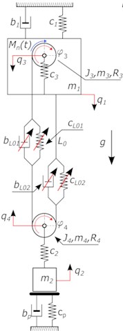
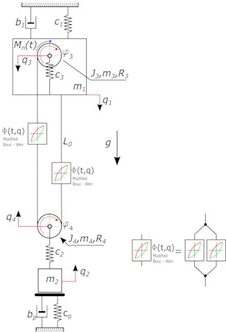
Numerical simulations of the lifting system for the designation of the dynamic surplus was carried out for two model solutions. Proposed model of lifting mechanism is shown in Fig. 4, while in the rest of the work will be respectively called a model of “KV” – where the rope is described using the model of Kelvin-Voigt [40], and the model of “BW” with rope described as a system of Bouc-Wen. In these models the following is assumed: reduction of the rope system to the duplicated one includes a variable and non-linear stiffness of the rope and its non-linear damping as a model of Kelvin-Voigt Fig. 4(a) and the model of the modified Bouc-Wen Fig. 4(b) representation of crane structure as a concentrated mass, omit the impact of deformability of headstocks, due to their much greater stiffness compared to the stiffness of the girder of overhead crane, approach taking into account both viscous and hysteresis at mapping damping occurring in the wire ropes, taking into account the characteristics of the engine used on the test object. By Fig. 4 kinetic energy, potential and dissipation function was determined:
Ep=0.5c1q21+0.5c3(q1-q3)2+0.5cpq22+0.5c2(q2-q4)2
+0.5cL01(-q4-q3+R3φ3-R4φ4)2+0.5cL02(-q4-q1+R4φ4)2,
ER=0.5b1˙q21+0.5bL01(-˙q4-˙q3+R3˙φ3-R4˙φ4)2
+0.5bL02(-˙q4-˙q1+R4˙φ4)2+0.5bp˙q22.
On the basis of the concept of generalized coordinates, and phenomenological model shown in Fig. 4, the equations of motion can be written as second type Lagrange equations [41]. This approach allows obtaining the differential equations of motion in the form of energy of the system. In the model following load cases will be considered: lifting cargo from the ground, where the rope in the start-up phase is loose and lifting the cargo from the ground at tightropes in the start-up phase. Because the system has the ability to directly control the cargo movement through the drive of the cable drum, thus being an alternative for a solutions according to the additional control equations based on the time constants [23], it was necessary to take into account the ground to hold the load in the early stages of the mass movement. The substrate serves as a platform for retaining load. The reaction of surface N was made dependent on displacement. At rest, the spring force and damping effect on the cargo. At the moment of separation cargo from surface, force has been excluded from the system:
Model takes into account dynamic forces in rope with the separation into the spring force and damping force where the stiffness of rope is described by Eq. (8), wherein the stiffness value of the of rope depends on its length:
L1(t)=(L0-R3φ3(t)),L2(t)=(L0-R4φ4(t)),
where: cL01 – stiffness of rope, nlin – number of tendons, AL – sectional area of the metallic cross section of wire rope, El – Young’s modulus of rope, L(t) – current length of rope. L0 – initial length of wire rope, R3 – radius of the cable drum, φ3 – rotation angle of the cable drum.
Fig. 4Phenomenological model of lifting mechanism, takes into account the reduced pulley system a) the rope as a model of Kelvin-Voigt b) the rope as a model of modified Bouc-Wen model, where: m3 – weight of the cable drum, m4 – pulley mass, b1 – girder damping, g – acceleration due to gravity, Mn – torque of the cable drum, c2 – rigidity of the hook, c3 – stiffness of the bearing axis of the cable drum, J3 – mass moment of inertia of the cable drum, J4 – mass moment of inertia of the pulley, R4 – radius of pulley, cp – stiffness of surface, bp – damping of surface, Фt,q – total force generated by the system with hysteresis
a)
b)
A variable damping factor of rope taken from publications [42] based on a dimensionless damping factor for a steel wire ropes is also implemented:
bL02(t)=2ζ√cL02(t)(0.5m2+nlini-1wρLAlL2(t)),
where: ζ– dimensionless damping coefficient for steel wire ropes, ρL – density of steel, m2– load weight.
Girder damping factor was determined from the relationship Eq. (10):
where: h – height of girder, Lmostu – bridge crane span, δ – logarithmic decrement, c1 – stiffness of the bridge crane girder, m1 – reduced mass of the girder.
Given dependence Eq. (10) on a logarithmic decrement of damping was included in [23] as a linear approximation based on defining the characteristics of dissipation of welded box girders described in [43], where a certain value is assumed, setting a ratio of the height of the girder to its span and assigns decrement value according to the recommended ranges. In the case of the model with a rope described using a model Bouc-Wen, respectively elastic force, and damping force have been replaced by a force generated by the system of equations of Bouc-Wen model. In order to model the assumed load cases should be taken into account the initial tension of the ropes. On the basis of the equations in Matlab Simulink dynamic models in the form of block diagrams were formulated. Table 6 contains physical parameters describing the dynamics of considered vibrating model, which were estimated by the technical documentation of lifting mechanism and own research.
Subsequently, a series of numerical experiments for presented data and initial conditions for hysteresis were assumed, and the classical model of elastic damping model was made. As the extortion, a drive system with the asynchronous motor was used. According to the norm, [44] HD1 class for lifting mechanisms without creep speed was considered.
Table 6Physical parameters describing the dynamic system
No. | Symbol | Value | Unit | No. | Symbol | Value | Unit |
Inertial elements | |||||||
1 | m1 | 5000 | [kg] | 17 | m4=m5=2m41=2m42 | 30 | [kg] |
2 | m2 | 1800 | [kg] | 18 | J4=J5=2J41=2J42 | 0.294 | [kgm2] |
3 | m3 | 280 | [kg] | 19 | J3 | 16.15 | [kgm2] |
4 | mliny | 20.5 | [kg] | ||||
Elastic elements | |||||||
5 | c1 | 4.6e6 | [N/m] | 21 | c2 | 2e7 | [N/m] |
6 | cp | 2.0e8 | [N/m] | 22 | c3 | 1.8e8 | [N/m] |
Damping elements | |||||||
7 | bp | 1.0e6 | [Ns/m] | 23 | b1 | 2.3e4 | [Ns/m] |
Other elements | |||||||
8 | R3 | 0.25 | [m] | 24 | R4=R5 | 0,14 | [m] |
9 | R3w | 0.23 | [m] | 25 | g | 9.81 | [m/s2] |
10 | dl | 0.012 | [m] | 26 | Vp | 0.208 | [m/s] |
11 | L0 | 10 | [m] | 27 | Vb | 0.416 | [m/s] |
12 | Al | 5.53e-5 | [m2] | 28 | ωb | 1.67 | [rad/s] |
13 | Es | 2.1e011 | [Pa] | 29 | nlin | 4 | [–] |
14 | El | 1.155e011 | [Pa] | 30 | ζ | 0.07 | [–] |
15 | ip | 60 | [–] | 31 | ρL | 7850 | [kg/m3] |
16 | iw | 2 | [–] | ||||
2. Results
The dynamic coefficients of surplus, obtained by numerical simulation of models and an applicable standard [44] are determined and compared below. The values of coefficients of dynamic surplus were compared with the experimentally obtained. Values of dynamic surplus determined for tight and loose ropes were made using a mechanical gauge (with a load of 1800 kg) with an indicator of the maximum value. Specific values of dynamic surplus obtained are summarized in Table 7.
Table 7Values of determined coefficients
Test | Nb. 1 | Nb. 2 | Nb. 3 |
Lifting the load from the ground – initial condition: loose ropes | 1.55 [–] | 1.45 [–] | 1.55 [–] |
Lifting the load from the ground – initial condition: ropes are strained | 1.31 [–] | 1.29 [–] | 1.32 [–] |
At present, applicable standard on the dynamic phenomena load carrying structures is a European standard EN 13001-2:2014 Crane Safety – General design – Part 2: Load actions. According to this standard, hoisting the load unconnected with the ground causes vibrations of the structure. These dynamic effects shall be taken into account by multiplying the gravitational force due to the mass of the hoist load by a factor φ2 [44]. The values of φ2 can be determined according to the standard with use of the Eq. (11):
where: β2– factor dependent upon the stiffness class of the crane, vh – characteristic hoisting speed of the load in [m/s], φ2,min– minimum value of φ2.
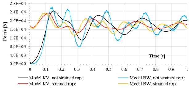
As can be seen in Fig. 5, 6 where the rope of lifting mechanism has been pre-tensioned, most of the presented models generated values of dynamic surplus very close to the actual value with an error of about 2 %.
A different situation occurs in the worst case, i.e. in regard to loose ropes. In Fig. 5, 6 can be clearly concluded that, for the case of extreme loads, the closest to the actual values was obtained for the model BW, where the differences are within 2 % with respect to dynamic surplus value, achieved on a real object. The worst, in this case, came out a model with a rope system modeled as a Kelvin-Voigt, where the differences are in the range of 9 % and a standard within the limits of 14 %, which does not take into account the shock loads caused by loose rope.
Fig. 5Values of dynamic factor for selected load cases and models, with differences in percentage in relation to the values, obtained on a research object
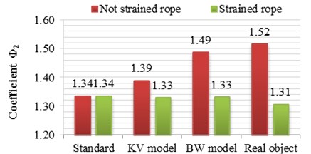
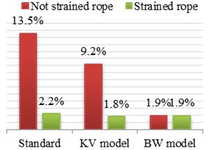
Fig. 6Forces in wire ropes for selected load cases
3. Conclusions
Modified Bouc-Wen Model used to describe the rope allows taking into account the mechanical properties of the rope to a dynamic model that maps lifting mechanism. Therefore, model tests improve and simplify the process of analyzing and determining the physical parameters for specific load conditions which are impact loads, at the cost of additional processes associated with the estimation of examined parameters. Accurately mapped characteristics such as load - unload represented by Bouc-Wen model, enables the study of the impact of applied wire rope model to the values of dynamic surplus in respect of e.g. normative values or received by values by the use of the classic elastic-damping model. Comparative analysis of the dynamic object, simulated by described phenomenological models, differing a way of modeling ropes, showed that consideration of the proposed method of mapping properties of the rope increases the accuracy of the calculations for the selected load cases. Bouc-Wen model that describes the rope, allows the implementation of the properties of the rope to a dynamic model, improving research model. Rope described by this model enables much more accurately mapped of dynamic states in the lifting mechanism for the case of impact loads, which can be caused by a loose rope. For standard load cases, i.e. for rope tight in the start-up phase, both the classical model as well as the proposed one, are characterized by high compatibility with the results of the real object and norm calculations.
References
-
Gąska D., Pypno C. Strength and elastic stability of cranes in aspect of new and old design standards. Mechanika, Vol. 17, Issue 3, 2011, p. 226-231.
-
Costello G. A. Theory of Wire Rope. Springer, 1997.
-
Feyrer K. Wire Ropes – Tension, Endurance, Reliability. 1st Edition. Springer-Verlag, Berlin-Heidelberg, 2007.
-
Hankus J. Structure and Mechanical Properties of Steel Wire Ropes. GIG, Katowice, 2000, (in Polish).
-
Chodacki J., Michlowicz E., Stupnicki S. Computer-Aided Design of Winch Crane. AGH, Kraków, 1998, (in Polish).
-
Grządziel Z. Three Mass Dynamic Model of Crane Hoisting Mechanism Equipped with a Hook. Technical Bulletin – OBRDiUT, Bytom, 1981, p. 23-29, (in Polish).
-
Haniszewski T. Hybrid analysis of vibration of the overhead traveling crane. Transport Problems, Vol. 9, Issue 2, 2014, p. 89-100.
-
Wojnarowski J. Models of Systems, Machine-Operator, to Reduce the Impact of the Oscillations Induced Intermittently. Gliwice, 1999, (in Polish).
-
Bisztyga K. Control and Regulation of Electric Motors. WNT, Warszawa, 1989, (in Polish).
-
Drozdowski P. Introduction to Electric Drives. PK, Kraków, 1998, (in Polish).
-
Gogolewski Z., Kuczewski Z. Electric Drive. WNT, Warszawa, 1984, (in Polish).
-
Grunwald Z. Electric Drive. WNT, Warszawa, 1987, (in Polish).
-
Zembrzuski J. Handbook Rewinding of Induction Motors. WNT, Warszawa, 2009, (in Polish).
-
Kaliński W., Margielewicz J., Wojnarowski J. Vibration Analysis of overhead cranes, caused by intermittent movement of cargo. Engineering Machines Problems, Vol. 13, 1999, p. 15-20, (in Polish).
-
Pu H., Xie X., Liang G., Yun X., Pan H. Analysis for dynamic characteristics in load-lifting system of the crane. Procedia Engineering, Vol. 16, 2011, p. 586-593.
-
Wojnarowski J., Margielewicz J. Generating dynamical characteristic of electromechanical system of a drive mechanism of an ovearhead travelling crane. Engineering Machines Problems, Vol. 12, 1998, p. 41-50, (in Polish).
-
Kastratović G., Vidanović N., Bakić V., Rašuo B. On finite element analysis of sling wire rope subjected to axial loading. Ocean Engineering, Vol. 88, 2014, p. 480-487.
-
Stanova E., Fedorko G., Fabian M., Kmet S. Computer modelling of wire strands and ropes. Part I: Theory and computer implementation. Advances in Engineering Software, Vol. 42, Issue 2011, 6, p. 305-315.
-
Stanova E., Fedorko G., Fabian M., Kmet S. Computer modelling of wire strands and ropes. Part II: Finite element-based applications. Advances in Engineering Software, Vol. 42, Issue 6, 2011, p. 322-331.
-
Tejszerska D. Modeling and Optimization of Shaft Hoists Dynamic. Silesian University of Technology, Gliwice, 2002, (in Polish).
-
Bogdevičius M., Vika A. Investigation of the dynamics of an overhead crane lifting process in a vertical plane. Transport, Vol. 20, Issue 5, 2005, p. 176-180.
-
Matyja T., Sładkowski A. Modeling of the Lift Crane Vibration Caused by the Lifting Loads. International Conference Zdvihací Zařízení vs Teorii a Praxi, Brno, 2007, p. 98-105.
-
Gąska D., Margielewicz J., Haniszewski T., Matyja T., Konieczny Ł., Chróst P. Numerical identification of the overhead traveling crane's dynamic factor caused by lifting the load off the ground. Journal of Measurements in Engineering, Vol. 3, Issue 1, 2015, p. 34-35.
-
Kosucki A., Malenta P. The possibilities of reducing the operational load of hoisting mechanisms in case of dynamic hoisting. Maintenance and Reliability, Vol. 18, Issue 3, 2016, p. 390-395.
-
Niu C. M., Zhang H. W., Ouyang H. A comprehensive dynamic model of electric overhead cranes and the lifting operations. Proceedings of the Institution of Mechanical Engineers, Part C: Journal of Mechanical Engineering Science, Vol. 226, Issue 6, 2012, p. 1484-1503.
-
Haniszewski T. Methodology for the estimation of parameters, of the modified Bouc-Wen model. Scientific Journal of Silesian University of Technology, Series Transport, Vol. 86, 2015, p. 45-53, (in Polish).
-
Metals – Tensile Test – Part 1: Method of Testing at Room Temperature. PN-EN ISO 6892-1:2010, 2010, (in Polish).
-
Ko J. M., Ni Y. Q., Tian Q. L. Hysteretic behavior and empirical modeling of a wire-cable vibration isolator. The International Journal of Analytical and Experimental Modal Analysis. Vol. 7, Issue 2, 1992, p. 111-127.
-
Mayergoyz I. D. Mathematical Models of Hysteresis. New York, Springer-Verlag, 1991.
-
Ni Y. Q., Ko J. M., Wong C. W., Zfaan S. Modelling and identification of a wirecable vibration isolator via a cyclic loading test. Part 1: Experiments and model development. Proceedings of the Institution of Mechanical Engineers, Part I: Journal of Systems and Control Engineering, Vol. 213, Issue 3, 1999, p. 163-171.
-
Nijmeijer H., Fey R. H. B., Aanhold J. E., Hulsen M. A., Nijmeijer H. Modelling and Identification of Dynamic Behaviour of a Wire Rope Spring. Report No. DCT-2004/28, Technische Universiteit Eindhoven, Department of Mechanical Engineering, Section Dynamics and control Technology, Eindhoven The Netherlands, 2004.
-
Oh J., Padthe A. K., Bernstein D. S., Rizos D. D., Fassois S. D. Duhem models for hysteresis in sliding and presliding friction. Proceedings of the 44th IEEE Conference on Decision and Control, and the European Control Conference, CDC-ECC, 2005, p. 8132-8137.
-
Visintin A. Differential Models of Hysteresis. Berlin, Springer, 1994.
-
Ikhouane F., Mañosa V., Rodellar J. Dynamic properties of the hysteretic BoucWen model. Systems and Control Letters, Vol. 56, Issue 3, 2007, p. 197-205.
-
Ikhouane F., Rodellar J. Systems with Hysteresis – Analysis, Identification and Control Using the Bouc-Wen Model. Chichester, UK, 2007.
-
Ismail M., Ikhouane F., Rodellar J. The hysteresis Bouc-Wen model, a survey. Archives of Computational Methods in Engineering, Vol. 16, Issue 2, 2009, p. 161-188.
-
Łazarz B. Identified Dynamic Model of Gear as the Basis for Design. Monograph, The Institute for Sustainable Technologies in Radom, Katowice-Radom, 2001.
-
Marchelek K. The Dynamics of Machine Tools. WNT, Warszawa, 1991, (in Polish).
-
Catalog of Electrical Machines INDUKTA. Ring Motors Series “e”. Bielsko Biała, (in Polish).
-
Margielewicz J., Haniszewski T., Gąska D., Pypno C. Model Studies of Cranes Hoisting Mechanisms. Monograph, The Committee on Transport. Polish Academy of Sciences, Katowice, 2013, (in Polish).
-
Cannon R. H. The Dynamics of Physical Systems. WNT, Warszawa, 1973, (in Polish).
-
Kim C. S., Hong K. S., Kim M. K. Nonlinear robust control of a hydraulic elevator: experiment-based modeling and two-stage Lyapunov redesign. Control Engineering Practice, Vol. 13, Issue 6, 2005, p. 789-803.
-
Piątkiewicz A., Sobolski R. Cranes. WNT, Warszawa, 1977, (in Polish).
-
Crane Safety – General Design – Part 2: Load Actions. PN-EN 13001-2:2014, 2014.
