Abstract
So far in engineering practice torsional and transverse vibration damping characteristics of the rotating systems were selected independently. This has resulted from the use of linearized equations of motion in calculations. Linearization results in the loss of information on the coupling between vibration. Currently, increase of the technical requirements to the rotating systems makes it necessary to conduct research in the non-linear range. Because the appropriate analytical methods for determining the form and frequency of vibrations in nonlinear systems are currently under development, simulation methods and analysis solutions in the time domain are growing in importance. In case of task consisting of selection an adequate torsional vibration damper, it is necessary to repeat the simulation calculations for the selected set of parameters, which is very time consuming and is a major drawback of this method. The aim of presented in the work simulation studies was a choice of such a torsional vibration damper, which also would reduce lateral vibration amplitude. The Matlab-Simulink environment and the library of Simulink blocks developed by authors and intended to model rotating systems, in any configuration, was used. Known in the literature the dynamic model of a broadband torsional vibration damper has been implemented in a form of an additional block of the above-recited library.
1. Introduction
Modern rotating power transmission systems used in broadly defined means of transport (in vehicles, ships and aircrafts) are the most popular mechanical systems for general use. The rational design methodology which allows for optimization of dynamic interactions in rotating systems, could reduce or eliminate the labor-intensive empirical researches in the manufacturing process. This issue becomes particularly important in the situation of increasing use of ultralight and resistant composite materials with dynamic parameters, which are highly non-linear [1, 2]. For this reason, it is substantial to improve a computation methods of rotating power transmission systems by increasing accuracy. This requires to resign from the simplifications of linearization and to apply models non-linear both geometrically (couplings of the flexural and torsional vibrations) and materially (nonlinear stiffness and damping).
So far, in the engineering practice, the frequencies of flexural and torsional vibrations were determined independently of each other, on the basis of linearized equations of motion [3, 4]. Also appropriate dampers were chosen independently. Unfortunately, the linearization of the equations of motion leads to loss of information on the coupling between vibrations. On the other hand, the analytical determination of the form and frequency of vibrations in nonlinear systems is a difficult task and the corresponding mathematical and numerical methods are currently being developed [5]. For this reason, the simulation methods which allow to solve a nonlinear equation of motion in time domain are becoming more essential. The disadvantage of simulation methods, in case of a question of an appropriate vibration damper choice, is the necessity of repeated calculations for a previously selected set of parameters.
The main objective of the study is to present proposals for selection methods the torsional vibration damper on the basis of the results of simulation studies carried out on the model of a rotating machine. An additional objective is to verify the thesis that in case of nonlinear systems, which take into account couplings between torsional and flexural vibrations, damping of torsional vibrations can reduce an amplitude of flexural vibrations during passage of a rotating system through critical states [6]. Thus vibration methods are widely used for develop and diagnosis of machinery, for example automotive vehicles [7, 8].
2. Rotating system model
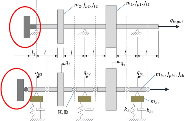
Simulation tests were conducted on the chosen model of a rotating system, which diagram is presented at the top in Fig. 1. The system consists of two thin disks (rotors) mounted on a shaft which is supported by three rolling bearings. At the right end of the shaft is installed a drive, which keeps changes of acceleration, speed and angle of rotation, programmed as a function of time (kinematic input). At the left end of the shaft possibility of mounting torsional vibration damper is provided. The most important parameters of the model can be found in Table 1.
Table 1Summary of the results characteristic for flexural vibrations
Damper parameters | Rotor 1 | Rotor 2 | ||
ωkr [rad/s] | Akr [mm] | ωkr [rad/s] | Akr [mm] | |
Without damper | 520.8 | 5.96 | 522.1 | 6.34 |
x1 | 469.3 | 4.82 | 470.0 | 5.64 |
x2 | 458.7 | 4.49 | 454.8 | 5.28 |
x3 | 445.5 | 4.19 | 446.1 | 5.04 |
x4 | 434.2 | 3.89 | 437.4 | 4.35 |
Fig. 1Scheme of the rotating machine with optional torsional vibrations damper and its dynamic lumped mass model
For the simulation studies the specialized Simulink library developed by the authors was used. The library enables simulation of dynamic phenomena in transient states of nonlinear rotating systems. The general conception of specialized Simulink library was described in works of the authors [9-11].
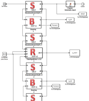
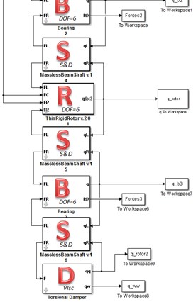
Rotating system is divided into rigid parts – inertial elements (rotors bearings and damper) and compliance parts (shaft sections) in a manner similar to the one used in the rigid finite element method [12]. Lumped mass dynamic model of the rotating system is shown at the bottom in Fig. 1. On the basis of this lumped mass model a corresponding simulation model is implemented in Simulink (Fig. 2) using the ready-made authors’ Simulink blocks. Parameters of blocks are adapted to properties of a rotating system.
Fig. 2Simulation model prepared in Simulink
3. Simulation start-up and forced torsional vibrations without damper
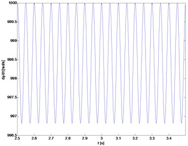
Preliminary simulations of start-up of the rotating system without a torsional damper revealed that spectrum of torsional vibration velocity is dominated by the frequency 20 Hz. Subsequently, start-up is simulated at the time of 2.5 s with rotating speed up to 1000 rad/s and acceleration varying sinusoidally, as shown in Fig. 3. After obtaining the nominal speed oscillations of acceleration with a resonance frequency 20 Hz were programmed, which resulted in fluctuations of speed in range of about 997÷1000 rad/s (Fig. 4).
Fig. 3The programmed drive acceleration change as function of time
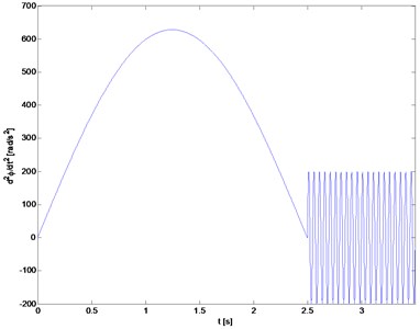
Fig. 4Fluctuations of the drive speed after reaching the nominal speed
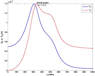
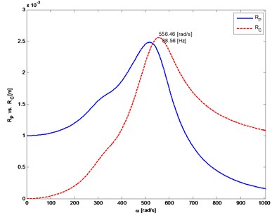
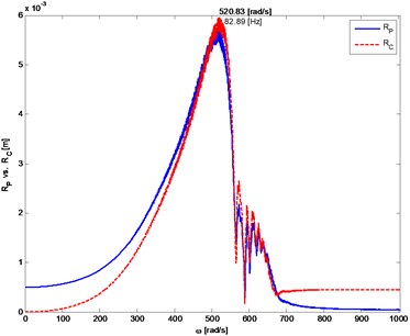
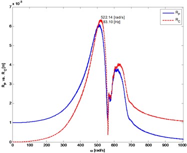
Non-linear, progressive stiffness characteristic of a shaft is assumed, which results in a significant increase in the amplitude of transverse vibration and shifting critical speeds. As a critical speeds are considered speeds of rotors, at which transverse vibration amplitudes of rotors reached extreme values [13]. The differences between vibrations of systems with linear or non-linear shaft’s stiffness illustrate the simulation results shown in Fig. 5 and Fig. 6.
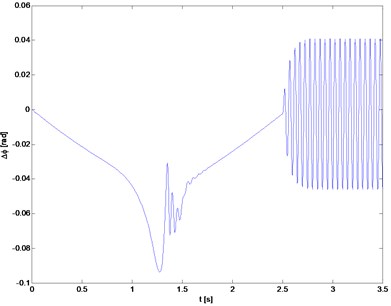
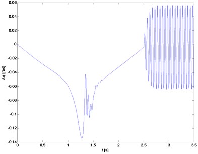
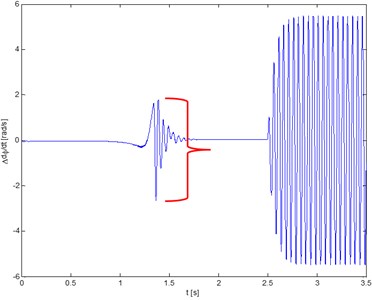
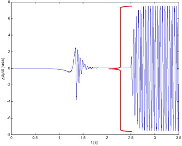
The results obtained for the system without damping are reference values for models with torsional vibration damper. Fig. 7 presents changes in time of rotor’s angle of rotation with respect to drive and changes of relative speed (as shown in the drawings), which can be considered as torsional vibrations. To evaluate the effectiveness of damping different measures can be used. However, in this studies a simple measure of torsional vibration is selected, which compares ranges of change in torsional vibration speed during start-up and similarly during motion at the nominal speed, with imposed oscillations (Fig. 8). In addition, the frequency of critical vibrations and the maximum flexural deflection are compared.
Fig. 5The distance from the axis of rotation of the mass center (P) and the geometric center (C) of the rotor depending on rotor’s angular velocity. The system with linear stiffness of the shaft
a) Rotor 1
b) Rotor 2
Fig. 6The distance from the axis of rotation of the mass center (P) and the geometric center (C) of the rotor depending on rotor’s angular velocity. The system with non-linear progressive stiffness of the shaft
a) Rotor 1
b) Rotor 2
Fig. 7Angle of torsion of the rotor relative to the motor
a) Rotor 1
b) Rotor 2
Fig. 8Torsional vibrations velocity
a) Rotor 1
b) Rotor 2
4. Dynamic model of flexural vibrations damper
A typical torsional vibration damper can be considered as a thin rigid disc (hub) in respect to which moves inertial ring (Fig. 9). The relative movement of the inertial ring is usually limited by an elastic element and is damped e.g. by Coulomb friction without lubrication, by internal friction or by viscous damping.
In general, movement of a damper hub can be described by the same equations, which describe the dynamics of statically and dynamically unbalanced rotor with six degrees of freedom [14, 15]. However, most commonly static and dynamic unbalance of damper is negligibly small. Dampers are typically mounted in rotating systems in such a way that gyroscopic effects are also very small. In the case of an isotropic rotor perfectly balanced statically: e=0 and dynamically: J33=Jp, J11=J22=Jt, it can be shown [13] that if factors containing small angles ψ, θ are omitted, damper hub equations of motion can be presented in a simplified (approximate) form:
¨θJt-˙φ˙ψJp=My,m¨y=Fy,
¨φJp+˙ψ˙θJp=Mz,m¨z=Fz.
In Eqs. (1) forces and moments of forces are expressed in the global system, coordinates {x,y,z} describe position of the center of mass of damper, Euler angles {ψ,θ} describe gyroscopic effects and φ is the rotation axis of damper.
In the simplest case it is sufficient to consider only a rotation of inertial ring with respect to hub. However, in this way gyroscopic effects are ignored, what effects an uneven pressure between hub and inertial ring and may have an impact on calculations of the moment of friction.
In paper [16] a generalized model of broadband torsional vibration damper, which can work in serial or parallel mode, is proposed (rys.2). The broadband damper consists of three rings of inertia, on non-linear spring and three nonlinear viscous dampers. Two dampers are connected in series with the hub: rubber damper and viscous damper. Additional viscous damper is also connected in parallel with the hub. From the model, by turning off the respective degrees of freedom one can obtain different types of dampers: inertial damper, classic rubber damper and broadband rubber damper (rubber damper connected in series or in parallel to an additional viscous damper).
Assuming that movements of the hub and the inertial ring are in part performed jointly, the equations of motion of the broadband torsional vibration damper shall take the form:
(m+m1+m2+m3)¨z=Fz,
(Jt+J1t+J2t+J3t)¨ψ+˙θ(Jp˙φ+J1p˙φ1+J2p˙φ2+J3p˙φ3)=Mx,
(Jt+J1t+J2t+J3t)¨θ-˙ψ(Jp˙φ+J1p˙φ1+J2p˙φ2+J3p˙φ3)=My,
Jp¨φ+Jt˙ψ˙θ=Mz+Mz1+Mz2,J1p¨φ1+J1t˙ψ˙θ=-Mz1+Mz3,
J2p¨φ2+J2t˙ψ˙θ=-Mz2,J3p¨φ3+J3t˙ψ˙θ=-Mz3,
where:m, Jp, Jt – mass and moment of inertia of the hub, mi, Jip, Jit – mass and moment of inertia of rings, Mz1, Mz2, Mz3 – torques dependent on parameters of stiffness and damping:
Mzi=dViΔ˙φi+dVi3Δ˙φ3i,i=1,2,
where: Δφi=φi-φ is a relative movement of rings.
Thus, a simplified dynamic model of the broadband vibration damper has nine degrees of freedom. Identification of parameters of such a damper is still an open question and requires experimental evaluation.
Fig. 9The general idea of torsional vibration damper which contains an inertial element performing relative movement
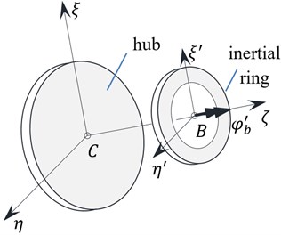
Fig. 10Model of the broadband torsional vibration damper (based [14])
![Model of the broadband torsional vibration damper (based [14])](https://static-01.extrica.com/articles/16415/16415-img15.jpg)
5. Selection of torsional vibration damper
The issue of selection the optimal torsional vibration damper, which also damps flexural vibrations, is a complex, multi-parameters and multi-criteria optimization problem. Due to used research methods, additional difficulty is the fact that after each change of damper parameters it is necessary to simulate and analyze generated vibration signals.
Table 2The most important design features of the model of a rotating machine
Rotor 1: m=6.0788kg, Jp=0.01873 kg m2, Jt=0.01018 kg m2, e=0.0005 m, γ=0.5° | |
Rotor 2:m=4.5525 kg, Jp=0.01405 kg m2, Jt=0.0075 kg m2, e=0.001 m,γ=0.5° | |
Shaft: d=0.012 m, l=0.072 m, l1=0.024 m | |
Bearings: mh=1 kg, khx=khy= 106 N m-1, bhx=bhy=2∙102 N s m-1, bψ=bθ=5 N m s∙rad-1 | |
Torsional Damper: m=1 kg, Jp=0.0017 kg m2, Jt=0.00083 kg m2, m1=0.5 kg, J1p=0.0034 kg m2, J1t=0.00166 kg m2, k1=52 N m rad-1, d1=0.025 N m s∙rad-1, m2=0.4 kg, J2p=0.0008 kg m2, J2t=0.0004 kg m2, d2=0.1 N m s∙rad-1 | |
Legend: | Jp – polar mass moment of inertia; Jt – transverse mass moment of inertia; e – static unbalance; γ – dynamic unbalance. |
Below the selection of damper having satisfactory performance is achieved by testing method, with a hand-controlled changes of parameters. At the very beginning damper is chosen arbitrarily, with parameters given in Table 2. A variant of the parallel broadband damper is used. The moment of inertia of ring of a rubber damper and a stiffness of rubber is selected such that the frequency of oscillation corresponds to the frequency 20 Hz (Frahm’s eliminator of vibrations).
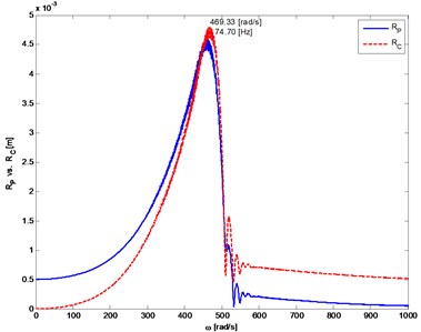
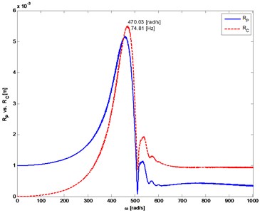
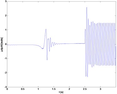
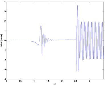
The results of the simulation of system with a damper are shown in Figs. 11 and 12. After applying the damper, the amplitude of torsional vibration is reduced, both during the start-up phase as well as during the movement with forced changes in speed (less than 30 % of the reference value). Also flexural vibrations are decreased (Table 1 results indicated by „x1”).
Fig. 11The distance from the axis of rotation of the mass center (P) and the geometric center (C) of the rotor
a) Rotor 1
b) Rotor 2
Fig. 12Torsional vibration velocity
a) Rotor 1
b) Rotor 2
The next simulations are carried out by changing only one parameter of the damper – by reduction (to 75 %) and increasing (up to 125 %, 150 % and 175 %) the stiffness of rubber. It appears that these changes deteriorate damping of torsional vibrations in the movement phase with nominal speed. But they have no noticeable impact on flexural and torsional vibrations during start-up (Fig. 13).
Then the moment of inertia (mass) of the ring of rubber damper and proportionally the stiffness of rubber are increased (2, 3 and 4 times), so as to maintain a constant value of ratio k/Jp. In case of torsional vibrations forced by changes of speed, the best results are obtained by doubled the mass (Fig. 14). Further increasing of the moment of inertia and the mass of a damper reduces amplitudes of flexural and torsional vibrations during start-up, but in a relatively limited range (Fig. 15 and Table 1).
Use of damper with too large mass needlessly increases the moment of inertia of the whole rotating system. For this reason, the damper indicated in Table 1 by symbol “x2”, with doubled mass and stiffness of the rubber in comparison to that adopted at the beginning of the research (Table 2) seems to be the best choice.
Fig. 13The dimensionless amplitude of velocity of torsional vibration at phase of movement forced by changing speed of drive, depending on stiffness of rubber
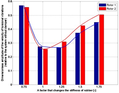
Fig. 14The dimensionless amplitude of velocity of torsional vibration at phase of movement forced by changing speed of drive, depending on the moment of inertia and stiffness of rubber
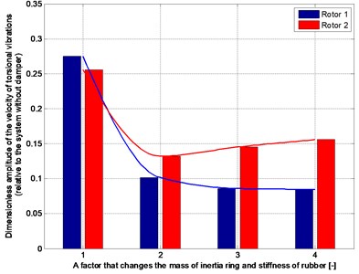
Fig. 15The dimensionless amplitude of velocity of torsional vibration at start-up and passage through the critical zone
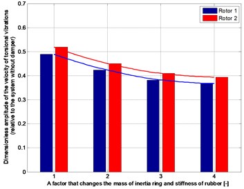
Damper that is selected in the manner described above reduces torsional vibrations amplitude of both rotors of nearly 90 % in case of motion with periodic changes in speed of drive. Damper also reduces the amplitude of the flexural vibration during start-up by approximately 20 % and torsional vibration associated with the passage through the critical zone by approximately 65 %.
6. Conclusions
The conducted simulation studies demonstrate the existence of strong coupling between flexural and torsional vibrations that should be considered when designing vibration damping elements. During start-up of the system and crossing through critical states flexural vibrations are a source of torsional vibrations. As further movement takes place in the supercritical range, forced by the drive torsional vibrations (if they do not alter dramatically the nominal speed) are very slightly transmitted to the flexural vibrations.
It is shown that torsional vibration damper can perform in the system two roles simultaneously. Moment of inertia of the ring and stiffness of rubber has a decisive influence on the degree of damping of torsional vibrations. These parameters do not affect noticeably on damping bending (flexural) vibrations. In contrast, the mass of damper determines the critical frequency of flexural vibrations. In analyzed model damper lowered values of critical velocities and the maximum displacements of the rotors’ centers, as well.
The proposed methodology for selection of the damper in the rotating system based on the results of simulation is although quite laborious and difficult to automate, but as shown in the example can quite effectively reduce vibrations levels.
References
-
Deuszkiewicz P. Research of static and dynamic properties of machine shafts made of carbon-epoxy composite. Scientific Journal of Polish Naval Academy, Vol. 185A, 2011, p. 75-82, (in Polish).
-
Deuszkiewicz P., Dąbrowski Z. Nonlinear dynamic model of carbon-epoxy composite structure. 20th International Congress on Sound and Vibration, Bangkok, Thailand, 2013.
-
Batko W., Dąbrowski Z., Kiciński J. Nonlinear effects in technical diagnostics. The Institute for Sustainable Technologies – PIB, Radom, 2008, (in Polish).
-
Dąbrowski Z. Machine Shafts. PWN, Warszawa, 1999, (in Polish).
-
Warmiński J. Nonlinear Forms of Vibrations. Discrete Systems. PWN, Warszawa, 2011, (in Polish).
-
Dabrowski Z., Starczewski Z. Influence of torsional vibration damping on critical states of nonlinear systems. 11th Pan-American Congress on Applied Mechanics, Foz do Iguacu, Parana, Brazil, 2010.
-
Burdzik R. Implementation of multidimensional identification of signal characteristics in the analysis of vibration properties of an automotive vehicle’s floor panel. Eksploatacja i Niezawodność – Maintenance and Reliability, Vol. 16, Issue 3, 2014, p. 439-445.
-
Burdzik R., Konieczny Ł. Application of Vibroacoustic Methods for Monitoring and Control of Comfort and Safety of Passenger Cars, Mechatronic Systems, Mechanics and Materials II. Book Series: Solid State Phenomena, Vol. 210, 2014, p. 20-25.
-
Łazarz B., Matyja T. Simulation of the non-steady states in rotating power transmission systems with use of Simulink. 20th International Congress on Sound and Vibration, Bangkok, Thailand, 2013.
-
Matyja T. Simulink library project for modeling and simulation of dynamic phenomena in rotating power transmission systems. 5th International Scientific Conference on Transport Problems, 2013.
-
Matyja T., Łazarz B. Simulation studies of the effect of shaft's nonlinear flexural stiffness parameters for critical states of rotating power transmission systems. Solid State Phenomena, Vol. 236, 2015, p. 1662-9779.
-
Wittbrodt E. Adamiec-Wójcik I., Wojciech S. Dynamics of Flexible Multibody Systems: Rigid Finite Element Method. Springer, 2007.
-
Vance J., Zeidan F., Murphy B. Machinery Vibration and Rotordynamics. John Wiley and Sons, 2010.
-
Matyja T. Model of stiff rotor with six degrees of freedom. 20th International Congress on Sound and Vibration, Bangkok, Thailand, 2013.
-
Matyja T. The proposal of methodology for modeling coupled flexural-torsional vibrations in transient states of rotating systems. The Institute for Sustainable Technologies – PIB, Radom 2014, (in Polish).
-
Homik W. Broadband torsional vibration dampers. The Institute for Sustainable Technologies – PIB, Radom, 2012, (in Polish).
