Abstract
To avoid the failure of rope collision caused by large amplitude transverse vibrations, this study aimed to determine proper hoisting parameters of a multi-rope friction mine hoist. To explore dynamic behaviors of the hoisting catenaries with constant length and the vertical hoisting ropes with variable length which are both subjected to the periodic external excitations induced by the fluctuations of the head sheaves, a dynamic model was established and experimentally validated. Through comparative analysis, it was found that the large amplitude transverse vibrations are usually associated with hoisting catenaries. Hence, the effects of the hoisting parameters on the transverse vibrations of the hoisting catenaries were further investigated. The results show that large amplitude transverse vibrations will be excited when the external excitation frequency is within the dangerous resonance frequency range and possible rope collision is thereby induced. According to displacement-frequency response curves, employing analogy method, the proper maximum hoisting speed of the hoist and the hoisting rope tensions can be determined to decrease the large transverse amplitude to a safe one. Therefore, the failure of rope collision can be thoroughly avoided.
1. Introduction
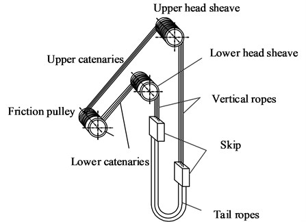
With the floor type multi-rope friction hoists being popularly applied in colliery, the failure of rope collision has been arisen as an intense problem. A multi-rope friction hoist in coal mines is shown in Fig. 1, steel wire ropes pass from the friction pulley over the head sheaves to the skip, forming four hoisting catenaries and four vertical ropes attached to four singular sheaves, respectively. A set of head sheaves consists of four singular sheaves, where one singular sheave is fixed at the shaft and the other three run freely. Considering the accuracy of manufacture and installation process of head sheaves, the inevitable circular degree and coaxial errors will induce periodic axial fluctuations of the four singular head sheaves. Periodic axial fluctuations will excite transverse vibrations of the catenaries and the vertical ropes, resulting in rope collision between the adjacent ropes due to large transverse amplitudes. As a result, the failure of rope will be accelerated and the possibility of the rupture of the rope is thereby increasing, which will certainly cause huge economic loss and influence safety of work in the surroundings. Therefore, it is of great significance to investigate transverse vibrations of hoisting ropes and optimize correlation hoisting parameters in order to avoid rope collision.
The axially moving catenaries with constant length and the vertically translating ropes with variable length in mine hoists can be viewed as taut axially moving strings that offer no resistance to bending. The transverse vibrations of an axially moving string with constant length have been extensively studied for many years, such as Sack studied a moving string subjected to a harmonic excitation at one eyelet, and determined the natural frequencies of the string by resonance relation [1]. A mathematical model representing the transverse vibrations of axially moving elastic strings, which considered tension and mass variation, was established to investigate the dynamic properties of a moving thread line [2]. The control and source identification problems for a viscoelastic string subjected to external traction have been studied by using moment theory [3]. The dynamic string motion, which displacement is unilaterally constrained by the rigid termination condition of an arbitrary geometry, has been simulated and analyzed [4]. Transverse oscillations in travelling strings due to arbitrary lateral vibrations of the supports have been studied by using the method of Laplace transforms [5]. And the transverse vibrations of axially moving strings and their controls have been thoroughly reviewed [6].
Fig. 1Schematic of a floor type multi-rope friction hoist in coal mines
Additionally, the lateral vibrations of vertically translating ropes with variable length have also been studied in recent years. The equations for a simplified and static elevator hoisting system in the vertical direction have been established, based on the theory of Mathieu equation, the reasons that cause the rope to vibrate laterally with constant, decaying and emanative amplitude has been analyzed [7]. The transverse vibrations of a rope in elevator system with time-varying length have been investigated by applying the continuum medium mechanics and considering the effect of the geometrically nonlinear kinematics of deformation, it turned out to be that the continuum medium mechanics can well describe the transverse vibrations of hoisting systems with time-varying length [8]. Governing equations and energy equations of the coupled vibration for the flexible hoisting systems with arbitrarily varying length have also been developed by using Hamilton’s principle [9]. And the lateral responses of vertically moving ropes in elevator system with variable length and tension, which subjected to general initial conditions and eternal excitation, have also been determined [10].
However, the literature that is specially related to transverse vibrations of hoisting ropes for mine hoists in coal mines is very limited. A view has been proposed that resonance will be excited when an external excitation frequency approaches one mode of natural frequencies of the rope in a single-rope mine drum hoist, however, the proposer didn’t study the influence factors [11]. With no regard to the transverse motions of head sheave, by employing the classical moving coordinate frame approach and Hamilton’s principle, a distributed-parameter mathematical model has been derived to investigate the dynamic behavior of a hoisting cable for a single-rope mine drum hoist [12].
From the literature studies mentioned above, few literatures have been focused on transverse vibrations of hoisting cables subjected to periodic axial fluctuations of head sheaves in a multi-rope friction mine hoist, and thus few control methods, such as parameter optimization, have been applied to reduce the large transverse vibration amplitudes.
The objective of the present study is to optimize the correlation hoisting parameters and thereby realize resonance avoidance of hoisting rope. A prototypical transverse vibration model for the catenary with constant length and the vertical rope with variable length was established, and the ordinary differential governing equations were derived by applying the Galerkin method. Experiment tests were carried out to validate the established model. Afterwards, dynamic analyses of the hoisting parameters were performed to find out the influencing factors affecting large amplitude transverse vibrations in hoisting ropes. Eventually, employing the analogy method, the maximum hoisting speed and the hoisting rope tension were optimized.
2. The dynamical model of the system
2.1. Governing equations of motion
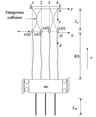
In order to describe the transverse vibrations of hoisting ropes in colliery, two fixed coordinate systems and are constructed, as shown in Fig. 2, which correspond to the catenaries and the vertical ropes, respectively. In this model, considering that the effect of gravity due to a catenary inclination is small as comparison to the total quasi-static tension, hoisting ropes are divided into four vertically translating catenaries with constant length and four vertical ropes with time-varying length in the same vertical plane as shown in Fig. 2. The skip is simplified as a rigid body of mass attached to the bottom ends of four vertical ropes, , and the suspension of the skip against guide rails is assumed to be rigid. In , considering that the axial fluctuations of the friction pulley are feeble and negligible, so the origin represents the friction pulley which is viewed as a fixed-center pulley without axial displacements. The four singular head sheaves are modeled as four particles subjected to axial displacement excitations induced by the axial fluctuations of the head sheaves, specified by , , and , where is hoisting time. During the hoisting process, the skip moves upwards. Then, the vertical hoisting rope has a variable length , an axial velocity and an axial acceleration . In order to explicitly illustrate transversely dynamic behaviors of the ropes, only the rope 4 and the head sheave 4 shown in Fig. 2 are adopted to conduct the research. For a vertically translating cable with arbitrarily varying length subjected to an external transverse excitation, the transverse vibration will play a dominating role in the forced longitudinal-transverse vibration, and the longitudinal vibration can be negligible [10]. Therefore, the longitudinal vibration is not considered in the present work.
In this study, the axially moving catenaries and vertical hoisting ropes in the multi-rope friction mine hoist can be modeled as taut strings. The equations governing the transverse vibrations of a string with variable length, velocity and tension can be formulated as [13-14]:
Fig. 2Schematic of the transverse vibration model for hoisting ropes
The boundary conditions are:
and the initial conditions are:
Similarly, the equations governing the transverse vibrations of a string with constant length and constant tension [15-18] can be formulated as:
The boundary conditions are:
and the initial conditions are:
where and are the transverse displacements of the rope particle instantaneously located in spatial position and at time relative to the fixed coordinate system and , respectively; and the subscripts , and denote the partial differentiation, is the mass of the hoisting rope per unit meter and is the equivalent damping coefficient which can be determined from the literature by Kaczmarczyk and Ostachowicz [19], the subscript 4 in will be omitted, is the axial tensile load located in spatial position at time in the vertically translating hoisting rope, arising from its own weight, the weight of the skip, the payload, the longitudinal acceleration and the time-varying mass of three tail ropes. In a multi-rope friction mine hoist, the tensions in the four hoisting ropes are required to be balanced, as a result, , which denotes the axial force of a single vertical rope can be formulated as:
where:
where the parameters and correspond to the mass of the skip and the payload, respectively, denotes the linear density of a hoisting tail rope, is the maximum length of vertical hoisting ropes, is the instantaneous length of a vertical hoisting rope and represents the minimum length of a tail rope during the ascending cycles, and is the acceleration of gravity.
Subsequently, according to the continuity of deflection across the head sheave, the axial tensile load in the catenary is required to be that is the axial force at the top of the vertical rope. There are three tail ropes with time-varying length attached at the bottom end of the skip. In a multi-rope friction mine hoist, the sum of the linear density of the three hoisting tail ropes is required to be equal to that of the four hoisting ropes, therefore, a quasi-static tension in the catenary at the constant speed stage can be formulated as:
2.2. Solution
It’s difficult to solve partial differential equation with time dependent nonhomogeneous boundary conditions. Especially the equation governing the transverse vibrations of a vertically translating rope is a complex partial differential equation, which has an infinite number of degrees of freedom and many time-varying parameters. As a result, it’s difficult to yield the precise analytical solution. To transform the partial differential equation with an infinite number of degrees of freedom to the ordinary differential equations with a finite number of degrees of freedom, the well-known Galerkin method can be adopted. Subsequently, numerical solution method, such as four-order Runge-Kutta method, can be used to solve ordinary differential equations.
In this section, Eq. (1) governing the transverse vibrations of a vertically translating rope with time-varying length is solved as an example. Firstly, the nonhomogeneous boundary conditions need to be transformed into the homogeneous. By employing the method presented by Zhu and Chen [10], the transverse displacement can be expressed as:
where is the part that satisfies the corresponding homogeneous boundary conditions and is the part that satisfies the corresponding nonhomogeneous boundary conditions. Substituting Eq. (10) into Eq. (1) yields:
where is the additional forcing term induced by transforming the governing equation with time dependent nonhomogeneous boundary conditions to one with homogeneous boundary conditions. The corresponding initial conditions for can be expressed as:
Substituting Eq. (10) into Eq. (2) and setting:
the homogeneous boundary conditions for can be obtained. And the function of can be expressed in a first-order polynomial in :
where and are the time-dependent unknown coefficients. Substituting Eq. (13) into Eq. (14) yields:
Subsequently, a new independent variable is introduced, and the time-varying spatial domain for can be converted to a fixed domain [0,1] for . The new dependent variable is and the new dependent variable for is . The partial derivatives of and with respect to and relative to those of and with respect to and are:
where subscript denotes the partial differentiation, and the asterisks in the new variables , and their derivatives are omitted in Eq. (16) and henceforth. Assume that the solution of infinite number of degrees of freedom for Eq. (1) can be formulated in the following form:
where represents the trial function, denotes the generalized coordinate, and is the number of truncation modes. Substituting Eqs. (15), (16) and (17) into Eq. (11), then multiplying Eq. (11) by , (1, 2,…, ) and integrating Eq. (11) over the interval of 0 and 1, ordinary differential equations can be obtained as:
where , the entries of the system matrices and the force vector are:
where is the Kronecker delta, if , then 1; if , then 0. For the established model in Fig. 2, the solution for is sought first, and then is obtained by applying Eq. (10).
Similarly, this method can also be applied to solve the partial differential Eq. (4) which governs the transverse vibrations of the catenary with constant length. Eventually, the ordinary differential equations transformed from Eq. (4) by using Galerkin method can be formulated as:
where . The entries of the system matrices and the force vector are:
2.3. The convergence of the solution
The convergence of the solution for the governing equations of the established models determines the accuracy of the solution. The convergence of the solution for each model in Fig. 2 can be examined by varying the number of included modes. To determine the number of included modes for Eq. (18) that governs the transverse vibrations of vertically moving hoisting ropes with variable length during the lifting process, a simulation external input, mm where v is the hoisting velocity and is the diameter of the head sheave, was used to simulate the axial fluctuations of the head heave. According to the hoisting velocity shown in Fig. 3 and the hoisting parameters given in Table 1, the transverse vibrations of the point at the vertical rope whose location is 20 m, , were calculated with different numbers of included modes as shown in Fig. 4.
Fig. 3The hoisting velocity and acceleration

a) Hositing velocity

b) Acceleration
Table 1Parameters of the hoisting system
Item | Notation | Value |
Rope spacing | 350 mm | |
Diameter of hoisting rope | 43 mm | |
Diameter of the head sheave | 4.5 m | |
Maximum hoisting speed | 9.36 m/s | |
Permitted maximum hoisting speed | 14 m/s | |
Constant length of the lower inclined catenary | 43.74 m | |
Maximum length of vertical hoisting rope | 699 m | |
Minimum length of hoisting tail rope | 14 m | |
Mass of full payload | 18000 kg | |
Mass of the skip and its additional devices | 17983 kg | |
Permitted maximum static tension of a rope | 900 kN | |
Equivalent damping coefficient | 0. 08 % | |
Young’s modulus of the hoisting rope | 11011N/m2 | |
Cross-sectional area of the hoisting rope | 1452.2 mm2 | |
Mass of the hoisting rope per unit meter | 7.86 kg/m | |
Mass of the hoisting tail rope per unit meter | 10.48 kg/m |
From Fig. 4, it can be seen that the convergence of Eq. (18) that governs the transverse vibrations of vertically moving hoisting ropes with variable length is basically achieved with 10. Thus, to guarantee the calculation accuracy, 20, the number of included modes, was selected for the vertical rope with varying length. Similarly, by varying the number of included modes, 4 was selected for the catenary with constant length.
3. Filed test and verification
In order to analyze the dynamic properties of the hoisting ropes and thereby determine proper hoisting parameters for the hoisting system, it is imperative to guarantee the validity of the established vibration model. The vertically translating ropes mainly move in deep coal mine, resulting in the difficulty in measuring the transverse displacements of the ropes by transducer during the lifting cycles. However, the transverse vibrations of the inclined catenaries which are above the ground can be easily acquired. Hence, the validity of the dynamic model can be confirmed by measuring the transverse vibrations of the axially moving catenaries.
Fig. 4The transverse vibrations of the point at the vertical rope whose location is x= 20 m

a) The overall time-domain plot

b) The partial enlarged time-domain plot
Real object tests were performed on a multi-rope friction hoist with four hoisting catenaries. In practical application, when the mine hoist operates at the constant speed stage without payload, the intense transverse vibrations are more likely to occur at the lower catenaries. Hence, a non-contact video gauge was utilized to measure transverse vibrations at the lower catenaries under the above working condition.
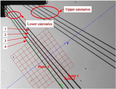
Fig. 5 demonstrates the non-contact video gauge processed image in which the four lower catenaries were marked with 1 to 4. The plane appearing as a red grid overlaid in the image in Fig. 5 is the coordinates frame to define the measuring scale of vibration displacements. The -axis is parallel to the longitudinal direction of the inclined catenaries while the -axis is parallel to the lateral. The scaling factor to the pixel measurements was calculated by two points over a known distance from point 1 to 2 shown in the image, and the distance between the two points is the rope spacing of 350 mm in the present study. In the present study, lower catenary 4 was taken as the analytical object for simplicity.
Fig. 5Non-contact video gauge processed image
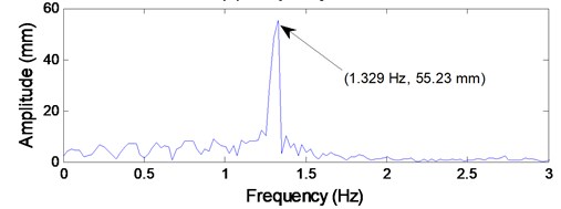
The time histories of the transverse amplitudes at the center of lower catenary 4 was given in Fig. 6(a), and the corresponding frequency spectrum shown in Fig. 6(b) was obtained by employing fast Fourier transform. It can be seen from Fig. 6(a) that the maximum transverse vibration amplitude at the center of lower catenary 4 is 166.8 mm; and the dominating vibration frequency component is 1.329 Hz with amplitude of 55.23 mm.
Fig. 6Test data of the transverse vibrations at the center of the lower catenary 4
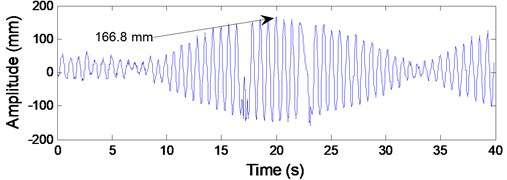
a) Time domain
b) Frequency domain
Fig. 7Test on the axial displacement of lower head sheave 4
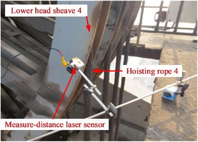
At the same time, due to the transverse vibrations of lower catenary 4 were induced by the axial fluctuations of the lower head sheave 4, a measure-distance laser sensor was used to detect the periodic axial fluctuating displacements of lower head sheave 4. The probe of the measure-distance laser sensor was adjusted to face the outer rim of lower head sheave 4 as shown in Fig. 7. The signals of the axial fluctuating displacements of the head sheave were recorded by Labjack which is a USB based measurement device that provides analog and digital inputs/outputs.
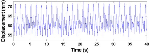
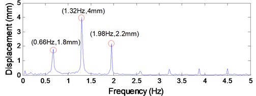
The axial fluctuating displacements of lower head sheave 4 at the constant speed stage in time domain are shown in Fig. 8(a), and the corresponding frequency spectrum is given in Fig. 8(b). The peak-to-peak value of the axial fluctuating displacement of lower head sheave 4 is 16 mm, which can be calculated from Fig. 8(a). And it can be concluded from Fig. 8(b) that the dominating excitation components are the first three order frequency components, the first three order excitation frequencies are 0.66 Hz, 1.32 Hz and 1.98 Hz, respectively, and the corresponding first order excitation amplitudes are 1.8 mm, 4 mm and 2.2 mm in sequence. Note that the rotational frequency of the head sheave is 0.66 Hz. Hence, it can be obtained that the rotational frequency of the head sheaves acts as the fundamental excitation frequency.
Fig. 8Test data of the axial fluctuating displacements of lower head sheave 4
a) Time domain
b) Frequency domain
Fig. 9The responses of transverse vibrations at the center of lower catenary 4 by numerical simulation
a) Time domain
b) Frequency domain
To validate the established dynamic model, the truly measured external excitation displacements shown in Fig. 8(a) are adopted as the inputs of Eq. (24) to calculate the responses of the transverse vibrations at lower catenary 4. The simulation working condition is the same as the measure working condition, that is to say, the responses of the model output are relative to the constant speed stage during the lifting process with no payload. According to the practical observation, the most severe transverse vibrations always occur at the center of the catenaries. Therefore, only the transverse amplitudes at the center of lower catenary 4 were considered.
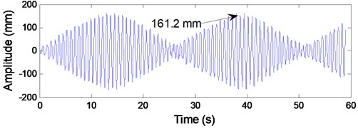
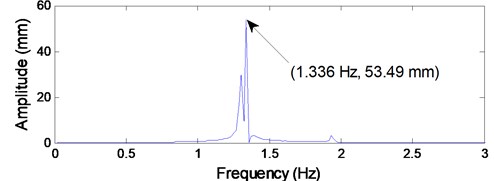
It can be seen from Fig. 9(a) that the shape of the vibrating waveform is well consistent with the practical measured vibrating waveform as shown in Fig. 6(a). The maximum transverse amplitude shown in Fig. 9(a) is 161.2 mm, which is much close to the practical measured value of 166.8 mm. In addition, according to the simulation result shown in Fig. 9(b), the dominating vibration frequency component is 1.336 Hz with amplitude of 53.49 mm, which is close to the measured value of 1.329 Hz with amplitude of 55.23 mm as shown in Fig. 6(b). Therefore, it can be concluded that the established coupled model is effective to describe the dynamic behaviors of the ropes subjected to axial fluctuations of the head sheave.
4. Dynamic analyses
4.1. Dynamic behavior of the vertical rope
Since the validity of the vibration model of the axially moving catenaries has been confirmed, and the modal approach has also been validated as comparison to the exact solution obtained by wave method [10], then the dynamic model can be also applied to the vertically translating ropes with time-varying length.
To predict the transverse vibrations at each point of the vertical hoisting rope 4 during the ascending cycles, the same truly measured displacement excitations shown in Fig. 8(a) are also employed as the inputs of Eq. (18), and the other hoisting parameters are the same as shown in Table 1. The simulation working condition is the same as the measure working condition in Section 3. Then the responses of the transverse vibrations at the vertical rope 4 can be calculated.
In the present study, aiming at preventing rope collision, the largest amplitude at each point of the vertical rope was investigated as shown in Fig. 10. Under the same external excitation, the largest amplitude at lower catenary 4 is 166.8mm as shown in Fig. 6(a) relative to the ascending cycle with no payload, while the largest amplitude at the vertically translating rope 4 is 33.06 mm as shown in Fig. 10. Hence, the transverse vibrations at the inclined catenary with constant length are much more severe than those in the vertical hoisting rope. Furthermore, it can be also obtained that the transverse vibrations at the vertical rope are of small amplitude and of a wide range of frequencies, mainly at the upper level of the shaft, which verifies the conclusion presented by Kaczmarczyk and Ostachowicz [12]. Thus, in the point of avoiding rope collision, the transverse vibrations of the vertical rope can be negligible.
4.2. Dynamic analyses of transverse vibrations of hoisting catenaries
According to the analyses mentioned above, the lateral vibrations are usually associated with the catenaries in a multi-rope friction hoist in coal mines, then it is necessary to explore the effects of the hoisting parameters on the lateral vibrations of catenaries.
The hoisting velocity mainly governs the axial fluctuations of head sheave that act as the external excitations, and the rope tension influenced by the hoisting load mainly governs the intrinsic frequency of the catenary. According to literature [11], intense transverse vibrations of catenaries will be excited if the external excitation frequency approaches the intrinsic frequency of the catenary. Therefore, this section mainly investigates the effects of hoisting velocity and load on the transverse vibrations of hoisting catenaries.
4.2.1. Effect of hoisting velocity on the transverse vibrations of hoisting catenaries
It has obtained from Section 3 that the first three order frequency components play the dominating roles in the periodic axial fluctuations of the head sheaves. The first three order excitation frequencies are 0.66 Hz, 1.32 Hz and 1.98 Hz, respectively, and the corresponding excitation amplitudes are 1.8 mm, 4 mm and 2.2 mm in sequence. Therefore, the corresponding first three order angular frequencies are 4.16 rad/s, 8.32 rad/s and 12.48 rad/s, respectively. The external excitation is specified by mm, the excitation amplitude is assumed to be a constant value of 4 mm which is the maximum excitation amplitude, represents the excitation order. And the other hoisting parameters are the same as shown in Table 1. The effect of hoisting velocity on the transverse vibrations of catenaries was demonstrated in Fig. 11.
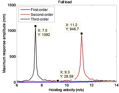
Under the circumstance of full payload, it can be seen from Fig. 11 that the transverse vibrations of hoisting catenaries under the second- and third-order excitations have discrepant larger responses than those under the first-order excitation. Especially when the hoisting velocities are 7.5 m/s and 11.2 m/s, the maximum transverse displacements of the hoisting catenaries are as large as 1092 mm and 946.7 mm which have seriously exceed the rope spacing of 350 mm in the present study, and collision between the two adjacent ropes will certainly resulted in as shown in Fig. 2.
Fig. 10The largest transverse displacements of the vertical rope 4 at each depth by prediction
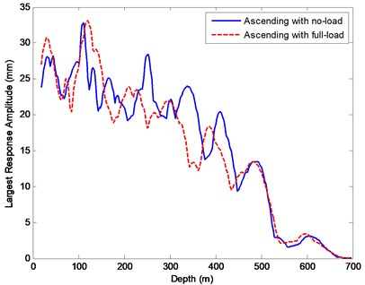
Fig. 11The maximum transverse displacements at the center of a catenary with varying constant velocities under the circumstance of full payload
4.2.2. Effect of hoisting load on the transverse vibrations of hoisting catenaries
To further investigate the effect of hoisting load on the transverse vibrations of hoisting catenaries, three typical working conditions which are ascending with no-load, full-load and part-load are considered. According to Eq. (9) and Table 1, the tensions in a single catenary under the three typical working conditions are 101000 N, 146000 N and 121000 N, respectively. By varying the excitation frequency under the excitation mm, the largest transverse amplitudes at the center of a lower catenary are depicted as shown in Fig. 12.
From Fig. 12, it can be seen that the resonance frequency curve towards right moves with the increasing rope tension decided by the hoisting load. During the ascending cycle with no-load, it is obvious that the second-order excitation angular frequency of 8.32 rad/s is more close to the resonance frequency range, the second order response amplitude at the center of the lower catenary is 151.9 mm which is much larger than the first-order (2.3 mm) and third-order (11.25 mm) as shown in Fig. 12.
Note that the sum of the first three order response amplitudes is 165.45 mm, which is so close to the practical value 166.8 mm shown in Fig. 6(a), so it has indirectly confirmed the validity of the established model. Additionally, it can be also concluded that, during the dynamic analyses and the latter parameter optimization, it is of no influence to replace the measured first-order excitation amplitude of 1.8mm and the third-order excitation amplitude of 2.2 mm by a larger value of 4 mm. And it is apparent that the second-order response amplitude of 12.69 mm relative to the ascending cycle with full-load is far less than 151.9 mm relative to the ascending cycle with no-load in Fig. 12.
Therefore, it can be concluded that a large response amplitude will be excited when an excitation frequency approaches the dangerous resonance frequency range and the resonance frequency increases with the increasing tension of the rope. If the largest amplitudes are required to be within 50 mm, then a dangerous resonance frequency ranging from 7.7 rad/s to 10.3 rad/s can be determined as shown in Fig. 12.
Fig. 12The largest displacements at the center of a catenary in frequency domain
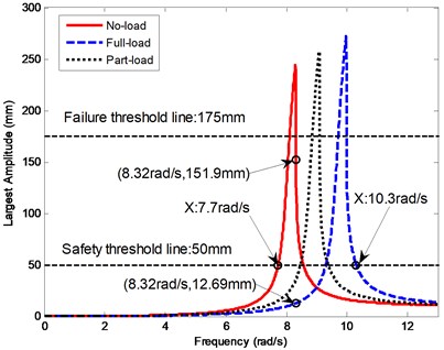
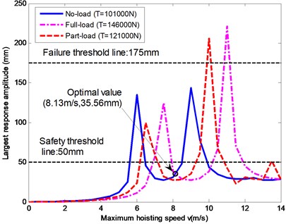
Fig. 13The numerical relationships between the largest response amplitudes of a catenary and the maximum hoisting speed
5. Determination of proper hoisting parameters
5.1. Speed optimization
The rotational frequency of the head sheave, which acts the fundamental excitation frequency, is determined by the hoisting speed of the catenary. Hence, to decrease the large transverse amplitude of 166.8 mm at the lower catenary 4 in this case, the excitation frequency can be changed to stay away from the resonance frequency range by varying the hoisting speed. The first three order frequency components play the dominating roles in the external excitations, considering the conclusion mentioned in section 4.2.2 that it is of no influence to replace the measured first-order excitation amplitude of 1.8 mm and the third-order excitation amplitude of 2.2 mm by a larger value of 4 mm, in this section, they are assumed as mm, mm and mm, respectively. Using the superposition principle, during the constant speed stage, the largest response amplitude (RF) at the center of the lower catenary 4 can be formulated as:
where 1, 2, 3. According to the displacement-frequency response curves given in Fig. 12, is the largest response amplitude under the excitation , is the optimal hoisting speed, is the diameter of the head sheave and is the permitted maximum hoisting speed given in Table 1.
Applying Eq. (30), under the three typical working conditions, the numerical relationships between the largest response amplitudes at a lower catenary and the maximum hoisting speed is given in Fig. 13. If the largest safe transverse amplitude of a catenary should be limited within 50 mm, by employing the analogy method, the maximum hoisting speed can be decreased from 9.36 m/s to 8.13 m/s as shown in Fig. 13. As a result, the largest amplitude of the lower catenary 4 in this case can be decreased from 166.8 mm to 35.56 mm.
5.2. Tension optimization
In colliery, if a smaller response amplitude of a catenary in mine hoists must be realized by decreasing the hoisting speed, then the yearly output of coal will decrease, leading to a lower financial reward. In view of this, speed optimization is not usually an economic way to deal with the large transverse amplitude. Hence, a new method must be developed to deal with this problem without changing speed.
In this section, maintaining the hoisting speed of 9.36 m/s unchanged, the external excitations are mm, mm and mm according to the on-site measurement, which are the same as those in Section 4. To reduce the largest response amplitude of a lower catenary without changing speed, the excitation frequencies should be beyond the resonance frequency range. Based on the conclusion that the resonance frequency increases with the increasing tension, then the tension in a catenary can be varied by adding clump weight to the skip. Thus, the updated tension in the catenary during the constant speed stage can be modified as:
where is the mass of additional clump weight. Under the three typical working conditions, employing the analogy method, the relationships between the largest response amplitudes at the center of the lower catenary and the tension increment are shown in Fig. 14. A smallest response amplitude, 31.42 mm, can be achieved when the tension increment of a rope is 26.7 kN. Then the maximum tension of a catenary during the ascending cycles with full load is 172.7 kN, which is far less than the permitted maximum static tension of the rope (900 kN given in Table 1). Therefore, tension optimization is effective and reliable. Substituting tension increment of 26.7 kN and other system parameters into Eq. (31), the mass of the additional clump weight can be calculated as 1.068×10⁴ kg.
Fig. 14The numerical relationships between the largest response amplitudes of a catenary and the tension increment
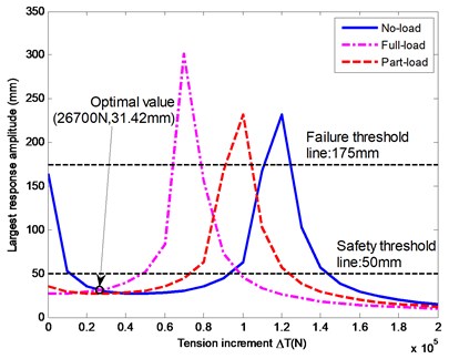
Fig. 15The non-optimal and optimal displacement-frequency curves
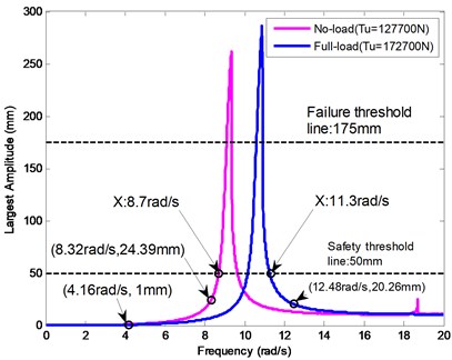
After tension optimization, the modified displacement-frequency response curves are depicted in Fig. 15. It can be seen from Fig. 15 that, under the same external excitation mm, the largest response amplitude has explicitly decreased from 151.9 mm (Fig. 12) to 24.39 mm, and the resonance frequency range has been transformed from 7.7 rad/s-10.3 rad/s to 8.7 rad/s-11.3 rad/s. Consequently, the three excitation frequencies, 4.16 rad/s, 8.32 rad/s and 12.48 rad/s, all locate outside the dangerous resonance frequency range, and the rope collision can be thoroughly avoided.
6. Conclusions
A dynamical model which can well describe the dynamical behaviors of the transverse vibrations of both the inclined catenaries with constant length and the vertical ropes with variable length in a multi-rope friction mine hoist was established and experimentally validated. Through comparative analysis, it was found that the large amplitude transverse vibrations are usually associated with the catenaries with constant length. Hence, to reduce the large transverse amplitudes, dynamic analyses and control measures were conducted on a hoisting system. According to dynamic analyses, it was found that a large transverse amplitude will be excited when an excitation frequency due to the periodic axial fluctuations locates in the dangerous resonance frequency range, eventually making rope collision possible. Then, the large transverse amplitude of a lower catenary, 166.8 mm, studied in this case has been decreased to 35.56 mm by optimizing the maximum hoisting speed from 9.36 m/s to 8.13 m/s. Besides, by varying the resonance frequency range, tension optimization was also conducted to decrease the large transverse amplitude from 166.8 mm to a safe value of 31.42 mm. As a result, the failure of rope collision in a multi-rope friction mine hoist can be thoroughly avoided, and the machine will certainly operate in health.
References
-
Sack R. A. Transverse oscillations in traveling strings. British Journal of Applied Physics, Vol. 5, 1954, p. 224-226.
-
Moustafa M. A., Salman F. K. Dynamic properties of a moving thread line. Journal of Engineering for Industry, Vol. 98, 1976, p. 868-875.
-
Pandolfi Luciano Boundary controllability and source reconstruction in a viscoelastic string under external traction. Journal of Mathematical Analysis and Applications, Vol. 407, Issue 21, 2013, p. 464-479.
-
Stulov Anatoli, Kartofelev Dmitri Vibration of strings with nonlinear supports. Applied Acoustics, Vol. 76, 2014, p. 223-229.
-
van Horssen W. T. On the influence of lateral vibrations of supports for an axially moving string. Journal of Sound and Vibration, Vol. 268, Issue 2, 2003, p. 323-330.
-
Chen L. Q. Analysis and control of transverse vibrations of axially moving strings. Applied Mechanics Reviews, Vol. 58, Issue 2, 2005, p. 91-116.
-
Zhang C. Y., Zhu C. M., Fu W. J. Nonlinear lateral vibration of the hoist rope in vertical hoist system. Journal of Shanghai Jiao tong University, Vol. 38, Issue 2, 2004, p. 286-290, (in Chinese).
-
Bao J. H., Zhang P., Zhu C. M. Modeling and analysis of rope transverse vibration for flexible hoisting systems with time-varying length. Journal of Shanghai Jiao tong University, Vol. 46, Issue 3, 2012, p. 341-345, (in Chinese).
-
Zhang P., Zhu C. M., Zhang L. J. Analysis of forced coupled longitudinal-transverse vibration of flexible hoisting systems with varying length. Engineering Mechanics, Vol. 25, Issue 12, 2008, p. 202-207, (in Chinese).
-
Zhu W. D., et al. Forced response of translating media with variable length and tension: application to high-speed elevators. Proceedings of the Institution of Mechanical Engineers, Part K: Journal of Multi-body Dynamics, Vol. 219, Issue 1, 2005, p. 35-53.
-
Gong G. F. Analysis of the string vibration for mine hoist. Mining Machinery, Vol. 12, 1990, p. 48-50, (in Chinese).
-
Kaczmarczyk S., Ostachowicz W. Transient vibration phenomena in deep mine hoisting cables. Part 1: Mathematical model. Journal of Sound and Vibration, Vol. 262, Issue 2, 2003, p. 219-244.
-
Zhu W. D., Ni J. Energetics and stability of translating media with an arbitrarily varying length. Journal of Vibration and Acoustics, Vol. 122, 2000, p. 295-304.
-
Sandilo Sajad H., van Horssen Wim T. On variable length induced vibrations of a vertical string. Journal of Sound and Vibration, Vol. 333, Issue 11, 2014, p. 2432-2449.
-
Ghayesh Mergen H. Nonlinear transversal vibration and stability of an axially moving viscoelastic string supported by a partial viscoelastic guide. Journal of Sound and Vibration, Vol. 314, Issues 3-5, 2008, p. 757-774.
-
Chen L. Q., Zhao W. J., Zu Jean W. Simulations of transverse vibrations of an axially moving string: a modified difference approach. Applied Mathematics and Computation, Vol. 166, Issue 3, 2005, p. 596-607.
-
Marynowski Krzysztof, Kapitaniak Tomasz Dynamics of axially moving continua. International Journal of Mechanical Sciences, Vol. 81, 2014, p. 26-41.
-
Kawamura Shozo, Shirashige Masaki, Iwatsubo Takuzo Simulation of the nonlinear vibration of a string using the cellular automation method. Applied Acoustics, Vol. 66, Issue 1, 2005, p. 77-87.
-
Kaczmarczyk S., Ostachowicz W. Transient vibration phenomena in deep mine hoisting cables. Part 2: Numerical simulation of the dynamic response. Journal of Sound and Vibration, Vol. 262, Issue 2, 2003, p. 245-289.
Cited by
About this article
The authors would like to thank anonymous reviewers for their constructive comments and thoughtful suggestions. This work is supported by the Priority Academic Program Development of Jiangsu Higher Education Institutions (PAPD).
