Abstract
As wind turbine blades tend to be long and narrow, the demand for its properties of bending resistance and vibration suppression is improving day by day. Mimicking the three-layer structure (the outer skin, the middle, the inner skin) of bamboo, this paper puts forward a new damping structure with the blade as a basic layer, one transitional layer and one free damping layer added to it. The formula of the structural loss factor is deduced by vibration differential equations. Then combined with the formula, the models of airfoil flutter and damping vibration suppression and related data, the numerical simulation is done using Matlab/Simulink Software. Consequently, the comparison diagrams of swing and wave velocity responses and their displacement responses between conditions with and without the new damping structure are gained, which indicates that the property of vibration suppression of wind turbine blades with the new damping structure is significantly improved.
1. Introduction
The wind turbine has long and narrow blades which vibrate under the influence of aerodynamic load, elastic force and inertial force. The most common and pernicious vibrations for large flexible blades are the aero-elastic coupling flutter and stall flutter [1]. Vibrations not only affect output power but also cause fatigue cracks and even damages on blades. Related scholars have made so many researches on the vibration phenomenon of wind turbine blades. Dossing proposes that the tuned vibration reducer is used to decrease vibration, which is difficult to implement. Murtagh, etc. raise that blades passive control is realized by the tuned mass damper to decrease the excitation force from the dynamic unbalance, but the tuned mass damper has poor adaptability. Thomas, etc. design an intelligent blade structure with variable trailing edges, but limited by the surface change rate of blade trailing edges, the effect of vibration suppression is not ideal. [2-4] John Montesanto [5], Stanciu Mariana Domnica, etc. [6]. set up a physical multi-scale progressive damage model to forecast the durability of blade structure and identify the risk areas of blade composite structures for material loading. They also studied the subcritical damage evolution and stiffness degradation of blade structures with finite-element analysis using computational micromechanics subroutines in continuum damage mechanics coupling framework to improve blade structure and lower production cost. It faces great innovations to improve blade structures, processing materials and modes [7, 8].
Bamboo possesses unique functional gradient structures to resist wind attacks. Domestic and foreign scholars have made so many researches on bamboo structures. Ma Jianfeng [9], etc. compare the anti-bending properties of the bionic bamboo structure with the traditional cylindrical shell by finite element simulation analysis. They draw a conclusion that the carrying capacity of the bionic bamboo structure is 1.25 times that of the traditional structure; T. Tan [10], etc. put forward a series of multi-scale experiments and numerical models to analyze the functional gradient structures of bamboo, and apply Yang modulus variation finite element model to analyze the mechanical property of bamboo in a fracture toughness experiment. Meisam K. Habibi [11], etc. study the asymmetric bending response of bamboo under different loading conditions by multiscale mechanical characteristics with a scanning electron microscope. The results show that bamboo fibers along the wall thickness of gradient distribution mainly affect the bamboo mechanical property. So, based on the different mechanical properties of bamboo structural parts, this paper tries to apply the bamboo three-layer structure to wind turbine blades to verify whether the vibration performance of the blades with the bionic three-layer bamboo structure is significantly improved with the help of vibration differential equations, the models of airfoil flutter and damping flutter suppression and the numerical simulation.
2. Materials and methods
2.1. Bionic damping structure analysis
Bamboo internal structure is shown in Fig. 1 [12]. Bamboo wall is composed of the outer skin, the middle and the inner skin. Their mechanical properties are closely related to their fiber volume fraction. The fiber volume fraction of the outer skin is the largest, the middle is less and the inner skin is least. It is true of their longitudinal elastic modulus and tensile strength. The reasons why bamboo has a superior ability to resist wind attacks are as follows: The outer skin has high elastic modulus and tensile strength, which can bear wind load in nature as a basic layer; Playing an important role in connecting the outer skin and the inner skin, the middle can dissipate part of the energy from wind load as a transitional layer; The inner skin can also dissipate part of the energy as a free damping layer. So, bamboo three-layer structure can be mimicked and applied to the wind turbine blade.
Fig. 1Bamboo internal structure. Note: 1 – outer skin, 2– middle, 3 – inner skin

2.2. Model analysis of the new damping structure
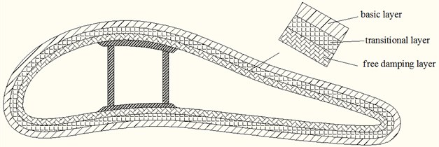
Mimicking the three-layer structure of bamboo, with the blade as a basic layer, one transitional layer and one free damping layer are added to form the new damping structure to suppress the blade vibration. The new damping structure is shown in Fig. 2.
Fig. 2New damping structure

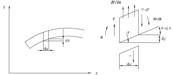
Bamboo wall thickness is far less than its length, and blade shell thickness is also far less than its wingspan length. So, the blade structure can be abstracted as a beam and its bending vibration theory can be adopted to analyze the blade dynamics performance. Fig. 3 is the bending vibration parameter specification for the new damping beam [13].
Fig. 3Bending vibration parameter specification for the new damping beam. Note: v is transverse vibration velocity; θ is bending angle displacement; P is transverse force; M is bending moment

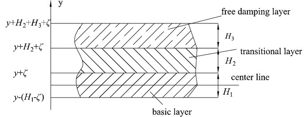
In order to determine the composite bending stiffness of the new damping beam, the center line of the barycenter should be determined first (as is shown in Fig. 4).
When the damping structural beam is bending, the elongation of the basic, transitional and free damping layers along the longitudinal direction varies with in a linear fashion:
The normal tensile and compressive stress in direction is as follows:
where 1, 2, 3 represent the basic layer, the transitional layer and the free damping layer respectively. The following formula can be gained by plugging Eq. (1) into (2):
Under pure bending, the force acting on the beam cross section along direction is equal to zero, that is:
Fig. 4Cross-section of the new damping structure: H1, H2, H3 are the thickness of the basic layer, transitional layer and the free damping layer, and ζ is the distance between the center line of the barycenter of the damping beam and the basic layer surface

The curvature is a constant. If the above formula is equal to zero, then:
By Eq. (2), can be expressed as:
After is determined, bending moment can be expressed as:
Plugging formula and Eq. (3) into (7), the following can be gained:
where , , , .
Eq. (6) can also be expressed as:
Plugging Eq. (9) into (8), the following can be gained:
where is the composite bending stiffness of the damping structural beam. is the bending stiffness of the ordinary beam.
Compared with the loss factor and of the viscoelastic damping materials on the transitional layer and free damping layer, the loss factor of the basic layer is so small that it can be ignored. Also, , , , and is the loss factor of the new damping structure. So, the following can be gained:
where , , and :
Omitting , and , the real component can be expressed as:
Omitting , and , the imaginary component can be expressed as:
Plugging Eq. (12) into (13) and omitting the higher-order item, the formula for can be expressed as:
From Eqs. (12) and (14), if the material elastic modulus of the new damping structure ( and ), the thickness ratios (and ), the loss factors ( and ), the bending stiffness of the basic layer without the damping structure () are known, the composite bending stiffness of the new damping structure () and the loss factor can be calculated.
2.3. Models of airfoil flutter and damping vibration suppression
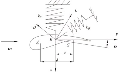
This study sets up the two degrees of freedom airfoil vibration dynamic model based on typical sections. Fig. 5 is the two degrees of freedom airfoil model and its coordinates.
Fig. 5Airfoil elastic supporting structure and coordinate system. Note: x stands for the vertical axis and the displacement of blade section. y stands for the horizontal axis. θ1 stands for the torsional angle of blade section. L stands the lift force. D stands for the drag force. The blade is supported by a twist spring kθ and a pull-press spring kx at the center of torsion E. The center of mass is G. The center of torsion is e. The aerodynamic center is A. A and G are δ apart

The classic vibration of blades is a sort of strong aeroelastic unstable phenomenon. Its main element is the blade torsion-bending-coupled vibration [14]. The two degrees of freedom airfoil dynamic Eq. (15) is deduced by Lagrange equation:
where is the airfoil moment of inertia about , is the torque acted on , and is the aerodynamic force acted on . is the distance between and . is the mass of airfoil cross section. and are calculated by blade material stiffness and airfoil parameters [15]. ( and are blade material shear modulus and elastic modulus. is the airfoil polar moment of inertia relative to . is the airfoil polar moment of inertia relative to the centroidal axis. is the distance between the airfoil cross section and the axis of rotation).
From the aerodynamic theory:
where is the airfoil chord length, is the blade cross section relative velocity, and is the air density. Eq. (16) can be also expressed as:
where , are the aerodynamic stiffness and damping of aerodynamic center.
Blades don’t vibrate under steady flow. Suppose blade cross section relative velocity is , attack angle is , and setting angle is at the steady-state moment. Take the airfoil at the distance of r away from the blade root as the research object. The following formula is derived from the airfoil velocity at the steady-state moment:
Among them, is velocity in wind wheel plane, , and is wind velocity, is axial inducible factor, is blade wheel rotational velocity, is tangential inducible factor
When the wind velocity changes, blades vibrate, the tangential velocity increment is , and the axial velocity increment is , and the torsional angle of blade section is –, the blade cross section relative velocity is as follows:
Then, the attack angle , the inflow angle , and its tangent function is as follows:
As both and have no relation with aerodynamic [16], so , .
Plugging and , the airfoil flutter equation is expressed as:
where , , . and are the structural stiffness and structural damping:
where:
If the material is assumed to be isotropic, the equivalent complex elastic stiffness of the structure can be expressed as:
As , the real and imaginary parts at both sides of the equation are equal. So, the following formulas can be deduced as:
Among them, is the moment of inertia of the damping structure to the neutral axis. The equivalent storage modulus and loss modulus can be calculated by Eqs. (23) and (24). So, with the damping material, the damping matrix in Eq. (21) can be expressed as:
In the matrix, 0.5 (), where is Poisson ratio. The analysis of the vibration suppression property of blades with the new damping structure can be done by plugging Eqs. (25) in (21).
3. Results and discussion
3.1. Numerical simulation experiment
A 600 kw wind turbine is selected in this simulation experiment, the blade shape of which adopts FX-77-153 aeronautics airfoil and the material is fiberglass. The main design parameters are shown in Table 1[17]. The airfoil section main design parameters are shown in Table 2 [18]. The lift and drag coefficient functions are obtained through polynomial fitting within the scope of the designed attack angle:
where is the lift coefficient, is the drag coefficient. The designed attack angle 10°, so 1.0314, 0.0248, 0.1043, 0.0028. The blade section parameters at the radius of 20 % to 30 % from the wing root was selected as the two degrees of freedom airfoil parameters, so 5 m, 0.38, 0.1128 [19] based on empirical models.
The matrixes of Eqs. (21) are calculated by the parameters in Table 1 and 2 and the related formulas:
Material parameters for the transitional layer is as follows: 0.5, 2.9×10⁸ Pa, 0.32; Material parameters for the free damping layer is as follows: 1.2, 1.14×10⁸ Pa, 0.5 .Without considering the temperature efficiency effect of damping materials, the structural damping . The properties of blade vibration and damping suppression are numerically simulated based on Eq. (21) by building simulation models in software Matlab/Simulink. Based on the ONERA non-linear aerodynamic model, the numerical simulations for the ordinary blade and the blade with the new damping structure are done under four different velocities: start-up wind velocity 4 m/s, rated wind velocity 15 m/s, machine halt wind velocity 25 m/s and dangerous wind velocity 45 m/s. Fig. 6 and 7 show the swing and wave velocity responses and displacement responses of the two blades under four different wind velocities.
Table 1Wind turbine main design parameters
Designed item | Output power / kW | Power coefficient | Rotor velocity / rad·s-1 | Rotor diameter / m | Designed attack angle / (°) | Setting angle / (°) |
Value | 600 | 0.4 | 7 | 40 | 10 | 1.63 |
Table 2Foil section main design parameters
Airfoil parameters | Chord length / m | Cross section mass per unit / kg | Moment of inertia / Kg·m-2 | Axial moment of inertia / cm4 | Polar moment of inertia / cm4 |
Value | 1.073 | 185.83 | 10.4 | 17364 | 673110 |
3.2. Analysis
From Fig. 6 and 7, as the wind velocity increases, the ordinary blade swing and wave amplitudes are increasing, and the wave displacement increases obviously; When the start-up velocity is rising to the machine halt velocity, the blade swing and wave amplitude are increasing slowly; When it is over the machine halt velocity, the blade vibration amplitude are increasing rapidly and significantly; When it reaches to the dangerous velocity, the blade cracks and even ruptures because the vibration amplitude exceeds the permitted value. For the damping blade, As the wind velocity increases, its swing and wave amplitude are also increasing, and the wave displacement increases within a small range; When the start-up velocity is rising to the machine halt velocity, its swing and wave amplitude are also increasing slowly; When it is over the machine halt velocity, the blade vibration amplitude increasement slows down significantly; When it reaches to the dangerous velocity, the blade doesn’t crack and rupture because the vibration amplitude is within the permitted value.
Fig. 6Ordinary and damping blades velocity responses. Note: compared with the ordinary blade, the standard deviation of the damping blade swing velocity decreases by 37.9 %, 35.0 %, 30.8 %, 25.0 % respectively; those of the wave velocity decreases by 51.1 %, 47.9 %, 43.7 % and 37.1 % respectively

a) Ordinary blade swing velocity

b) Damping blade swing velocity

c) Ordinary blade wave velocity

d) Damping blade wave velocity
Four structural loss factors (0.335, 0.323, 0.289, 0.241) of the damping blade under four different velocities are calculated by the swing and wave data. From Table 3, compared with the ordinary blade, the standard deviation of the damping blade swing velocity decreases by 37.9 %, 35.0 %, 30.8 %, 25.0 % respectively; those of the swing displacement decreases by 37.9 %, 34.8 %, 30.8 % and 25.2 % respectively; those of the wave velocity decreases by 51.1 %, 47.9 %, 43.7 % and 37.1 % respectively; those of the wave displacement decreases by 51.1 %, 48.1 %, 43.6 % and 37.1 % respectively. With the transitional and free damping layers on the blade, the damping blade vibration amplitude is smaller than the ordinary blade because of its lower natural frequency and higher structural loss factor. The damping blade vibration amplitude decreases more quickly than the ordinary within the same period because the transitional and free damping layers turn part of the vibration energy into heat energy. Through the numerical simulation experiment, it can be concluded that the vibration amplitude of the damping blade decreases sharply within a number of vibration periods, which can delay the fatigue damage process effectively, and the property of blade vibration suppression with the new damping structure can be improved significantly.
Fig. 7Ordinary and damping blades displacement responses. Note: compared with the ordinary blade, those of the swing displacement decreases by 37.9 %, 34.8 %, 30.8 % and 25.2 % respectively; those of the wave displacement decreases by 51.1 %, 48.1 %, 43.6 % and 37.1 % respectively

a) Ordinary blade swing displacement

b) Damping blade swing displacement

c) Ordinary blade wave displacement

d) Damping blade wave displacement
Table 3Simulation results
Operating conditions | Evaluation index | Swing | Wave | ||||||
Ordinary | Damping | Ordinary | Damping | ||||||
×10-2 | ×10-2 | ×10-2 | ×10-2 | ×10-1 | ×10-1 | ×10-1 | ×10-1 | ||
Set-up wind | Max. | 0.00 | 0.20 | 0.00 | 0.20 | 0.60 | 0.18 | 0.60 | 0.18 |
Min. | –0.41 | –0.21 | –0.40 | –0.20 | 0.00 | –0.19 | 0.00 | –0.17 | |
SD. | 0.09 | 0.09 | 0.07 | 0.07 | 0.17 | 0.103 | 0.14 | 0.08 | |
Rated wind | Max. | 0.00 | 0.23 | 0.00 | 0.22 | 0.79 | 0.21 | 0.78 | 0.20 |
Min. | –0.54 | –0.24 | –0.53 | –0.23 | 0.00 | –0.21 | 0.00 | –0.19 | |
SD. | 0.13 | 0.18 | 0.10 | 0.09 | 0.22 | 0.12 | 0.19 | 0.09 | |
Machine halt wind | Max. | 0.00 | 0.28 | 0.00 | 0.27 | 1.15 | 0.25 | 1.13 | 0.25 |
Min. | –0.78 | –0.29 | –0.77 | –0.29 | 0.00 | –0.24 | 0.00 | –0.23 | |
SD. | 0.20 | 0.15 | 0.16 | 0.11 | 0.34 | 0.15 | 0.29 | 0.13 | |
Dangerous wind | Max. | 0.00 | 0.37 | 0.00 | 0.36 | 2.00 | 0.34 | 1.99 | 0.33 |
Min. | –1.36 | –0.39 | –1.34 | –0.38 | 0.00 | –0.33 | 0.00 | –0.32 | |
SD. | 0.38 | 0.21 | 0.31 | 0.17 | 0.62 | 0.21 | 0.54 | 0.18 | |
Note: stands for displacement (m); stands for velocity (m/s). SD stands for standard deviation | |||||||||
4. Conclusions
Mimicking the three-layer bamboo structure (the outer skin, the middle, the inner skin), this paper puts forward a new structure (a basic layer, a transitional layer and a free damping layer) applied on wind turbine blades. It deduces the formula for that is the distance between the center line of the barycenter of the damping beam and the basic layer surface, the formula for the composite bending stiffness of the damping beam by vibration differential equations, and the formula for structural loss factor . Based on the models of airfoil flutter and damping vibration suppression, the numerical simulation experiment on a 600 kw wind turbine is done using Matlab/Simulink Software. Consequently, the comparison diagrams of swing and wave velocity responses and their displacement responses between conditions with and without the new damping structure are gained. From the diagrams, as the wind velocity increases, both the ordinary blade and the damping blade swing and wave amplitudes are increasing, but the ordinary blade waving displacement increases obviously, and the damping blade increases within a small range; When the start-up velocity is rising to the machine halt velocity, both the blades swing and wave amplitude are increasing slowly; When it is over the machine halt velocity, the ordinary blade vibration amplitude are increasing rapidly and significantly, but the damping blade vibration amplitude increasement slows down significantly; When it reaches to the dangerous velocity, the ordinary blade cracks and even ruptures because its vibration amplitude exceeds the permitted value, but the damping blade doesn’t crack or rupture because its vibration amplitude is within the permitted value. All the above indicate that the vibration amplitude of the damping blade decreases sharply within a number of vibration periods, which can delay the fatigue damage process effectively and the property of vibration suppression of wind turbine blades with the new damping structure is significantly improved.
References
-
Stemple A. D., Lee S. W. A finite element model for composite beams undergoing large deflection with arbitrary cross-section warping. International Journal of Numerical Method in Engineering, Vol. 28, Issue 9, 1989, p. 2143-2160.
-
Dossing O. Vibration control on huge wind turbine blades using tuned absorbers. Proceeding of International Modal Analysis Conference, Vol. 1, 1997, p. 216-222.
-
Murtagh P. J., Ghosh A., Basu B., et al. Passive control of wind turbine vibrations including blade/Tower interaction and rotationally sampled turbulence. Wind Energy, Vol. 11, Issue 4, 2008, p. 305-317.
-
Thomas B., Gaunaa M., Christian B. Potential load reduction using airfoils with variable trailing edge geometry. Journal of Solar Energy Engineering, Vol. 127, Issue 4, 2005, p. 503-516.
-
Montesano John, Chu Hao, Singh Chandra Veer Development of a physics-based multi-scale progressive damage model for assessing the durability of wind turbine blades. Composite Structures, Vol. 141, 2016, p. 50-62.
-
Domnica Stanciu Mariana, Loan Curtu, Lonut Tesula Structural optimization of composite from wind turbine blades with horizontal axis using finite element analysis. Procedia Technology, Vol. 22, 2016, p. 726-733.
-
McKenna R., v.d. Leye P. Ostman, Fichtner W. Key challenges and prospects for large wind turbines. Renewable and Sustainable Energy Reviews, Vol. 53, 2016, p. 1212-1221.
-
Lee Kyoungsoo, Huque Ziaul, Kommalapati Raghava, Sang-Eul-Han Evaluation of equivalent structural properties of NREL phase VI wind turbine blade. Material and Manufacturing Processes, Vol. 27, Issue 27, 2016, p. 1285-1289.
-
Ma Jian-feng, Chen Wu-yi, Zhao Ling, Zhao Da-hai Elastic buckling of bionic cylindrical shells based on bamboo. Journal of Bionic Engineering, Vol. 5, Issue 3, 2008, p. 231-238.
-
Tan T., Rahbar N., Allameh S. M., Kwofie S., Dissmore D., Ghavami K., Soboyejo W. O. Mechanical properties of functionally graded hierarchical bamboo structures. Acta Biomaterialia, Vol. 7, 2011, p. 3796-3803.
-
Habibi Meisam K., Samaei Arash T., Gheshlaghi Behnam, Lu Jian, Lu Yang Asymmetric flexural behavior from bamboo’s functionally graded hierarchical structure: underlying mechanisms. Acta Biomaterialia, Vol. 16, 2015, p. 178-186.
-
Yao Xishen Bamboo Culm Anatomy of China. First Edition. Science Press, Beijing, 2002.
-
Liu Lihua Viscoelastic Damping Vibration Reduction and Noise Reduction Application Technology. First Edition. Yu Hang Press, Beijing, 1990.
-
Hodges D. H., Dowell E. H. Nonlinear Equations of Motion for the Elastic Bending and Torsion of Twisted Nonuniform Rotor Blades. NASA TN D-7818, 1974.
-
Dowell Earl H., Clark Robert, Cox David, et al. A Modern Course in Aeroelasticity, 4th Edition. Kluwer Academic Publisher, USA, 2004, p. 64-85.
-
Liu Xiaoyan Analysis on Wind Turbine Blade Design and Stability. Northwestern Polytechnical University China, 2004.
-
Chinese National Standards GB-T25383-2010, 2010.
-
Dieter Althaus Niedrig Geschwindigkeits Profile. First Edition. Vieweg and Sohn Verlagsgesellschalt mbH, Braunschweig/Wiesbaden, 1996.
-
Liu Xiong, Chen Yan, Ye Zhiquan Research on the aerodynamic performance prediction model for horizontal axis wind turbine. Acta Energiae Solaris Sinica, Vol. 26, Issue 6, 2005, p. 792-800.
Cited by
About this article
The authors wish to express their sincere thanks to Liu Shizhong, Yan Bijuan, Song Yong of Damping Vibration Attenuation Laboratory of Taiyuan University of Science and Technology for their general guidance and technical advice.
