Abstract
The paper presented a multi-purpose system for testing of dental prostheses within the static and kinematic conditions as well as the conditions of its stability quick analysis. The common goal of prosthetics specialists is to define biomechanical criteria shaping the restorations to protect the existing state of the biological substrate [1]. In prosthesis biomechanics, the gingival soft tissue, as substances with heterogeneous properties, are difficult to individual assessment of the value, direction and duration of the occlusion forces transmitted by the prosthesis in the life cycle [2]. More predictable are static or kinematic behaviors, reflecting the mechanical states of prosthesis design with designed shape and material properties which are possible to determine. However, static measurements of dentures do not reflect their work in natural conditions [3], and can only designate the values of selected parameters (deflection, stress) during the reference of constant load values. The article presents the author’s research stand for kinematic loads testing, which are similar to natural ones during shredding of food. The results of stress and strain of denture prosthesis, identified during laboratory tests, will be used to verify the mathematical models of dentures during kinematic forces.
1. Introduction
The teeth condition among Polish citizens (and others) has systematically deteriorated over the recent decades. There are many reasons of this situation. They include, among others:
- general food and drink chemicalisation, as well as calcium, magnesium and potassium deficiencies,
- consumption of the above listed products since childhood,
- poverty in many families making rational nutrition impossible,
- increasingly difficult and expensive access to dental services,
- long waiting for dental treatment within the framework of the socialised health centre.
The above conditions lead to the fact that the permanent teeth lesions start among children and young people in the teenage years. The older population suffers from these symptoms almost entirely [4, 5, 6].
Natural "salvation" in this situation is to replace lacking teeth with artificial dental prostheses. One of the conditions required for prostheses, in addition to the conventional comfort and convenience, is their relatively high durability and stability while minimising the deformation under the influence of forces due to the jaws movement at biting food products [7, 9, 10, 11, 14].
Accordingly, there is a need to develop design criteria of the same construction dental prostheses that would have the above-mentioned features [8,12,13]. Therefore, the team of authors from the Institute of Electronic Systems of the Military University of Technology have been working on a method to objectively assess the prostheses operational quality [6, 13, 14].
2. Preparing a skeletal denture research
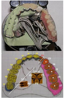
On the side of metal connectors of the experimental prosthesis wings with natural teeth, which are indeed a thin layer with an average thickness of 0.45 mm and an irregular surface tissues shape, foil strain gauges were fixed in the assumed places and directions of the metallic material deformation (Fig. 3).
Measuring transducers were placed in possibly flat areas (from the palate and inherent oral cavity) within the Wheatstone half-bridge system: two single strain gauges TF-1 with resistance R = 119.9 Ω ± 0.2% and a strain sensitivity coefficient k = 2.15 ± 0.5% as well as two rosette strain gauges of delta type TFr-8/120° o R = 120.2 Ω ± 0.2% and k = 2.15 ± 0.5% (TENMEX).
The alar cast partial with measuring transducers was placed on the base diagnostic model of the examined clinical case. It was made of the IV class (ISO 6873 / 83 – BegoStone plus) plaster with compressive strength up to 60 MPa, comparable with the periodontal fibre elastic resistance capacity of abutment teeth estimated at a physiological level of 67 MPa.
Fig. 1The experimental prosthesis and the arrangement scheme of measuring transducers
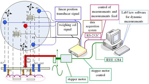
It is shown in Fig. 2. When designing this station, the particular attention was paid to the diagnostic signals [15-17] and the reliable operation [18-21] (both in terms of power supply systems [22, 23] as well as the impact of electromagnetic interference [24, 25]) by using appropriate reliability structures. During the design of the laboratory station, a manner of the force application, direction and variability in time.
Fig. 2Diagram of test station. Legend: stepper motor – to the cyclic reference force F0 applied to the canter of the rigid surface based on the three supports (F0, F1, F2, F3) located within the teeth of the prosthesis
In the analysed system, the variable forces, which cause deflection and deformation of the tested dental prosthesis, have a sinusoidal character, and their frequency does not exceed 2 Hz. The used measuring transducers and the amplifier have an influence on the dynamic properties of the measurement chain. In order to measure the deflection, the potentiometric transducer was applied. It includes an internal spring which ensures the contact reliability of the movable element with the potentiometer slide.
The potentiometer itself, by definition, can be treated as an inertia-free element, however, the spring (energy storage element) changes the nature of this transducer into the inertial one. The experiment was conducted, giving the unit step function to the input of the deflection transducer. The response to the unit step function is shown in the below figure.
Deformations of the surface based on the prosthesis (∆, , ) from the initial position of equilibrium, are measured by the three axial transducers (, , ).
The nature of replies allows to classify the transmitter to the inertial members of the first row. Basic frequency parameters, such as the phase shift and frequency limit, relevant to the determination of the dynamic distortions of the system during the variable signals processing, were defined, in an approximate way, on the basis of experimental research of step response of the analyzed system.
Fig. 3The response of the potentiometric transducer of linear shifts to the unit step function, legend: ht– step response – a response system for extortion in the form of stroke unit 1t
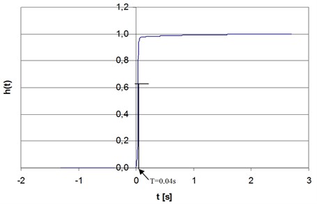
There were used experimental dependences, which bound the frequency and time dependences of systems. Time parameters such as rise time of characteristics, delay time, time constant have been determined experimentally (directly from the step response) as defined [26, 27]. The determined time constant value 0,04 s allows to specify the phase shift introduced by the transducer according to the Eq. (1) [28]:
The phase shift introduced by this transducer, for the frequency of 2 Hz, is 0,46 rad. The study of the response to the unit step function allows to approximately determine the upper corner frequency of the element in accordance with the Eq. (2) [28]. Rule (2) it is a technical way to determine the cut-off frequency of system , wherein the is a rise-time of step response in range from 0,1 to 0,9 of steady state:
where: , is time after which the sharp response of the layout reaches 0,1 steady state values, is time after which the sharp response of the layout reaches 0,9 steady state values.
In this case 8,75 Hz. It means that in the DC-2 Hz frequency band, the amplitude response is flat, and the transducer does not introduce the amplitude distortion (while biting the food, the effective load rate of each tooth is in the range of 40-120 cycles/min [8, 9]).
In order to measure the deformation, the tensometric transducers of the Hottinger Baldwin Messtechnik GmbH company were used. The tensometric transducer itself, in the above frequency band, based on the manufacturer's data, can be treated as an inertia-free transducer. In the measurement system, a single strain gauge is stuck in the selected location of the prosthesis and allows to measure deformation, which occurs in the area of its resistive grid. The dynamic properties of the section of the strain gauge-tested element mainly depend on the location in which the strain gauge is stuck on the prosthesis. The tested area of the prosthesis, depending on the location, may have a different nature.
As in case of the deflection transducer, two (stuck in different location) strain gauges were subject to extortion in the form of the unit step function.
Fig. 4The response of the tested elements of the prosthesis with the strain gauges to the unit step function
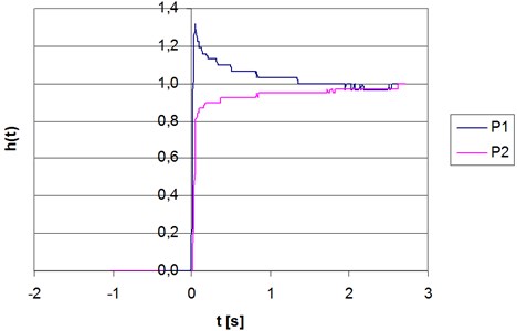
Strain gauges were stuck symmetrically to the prosthesis base, including the P1 prosthesis on the side of artificial teeth, and the P2 transducer on the side of the support clip. As it is seen in Fig. 4, the tested element with the P1 transducer shows the second order oscillating nature with dying oscillation, and the element with the P2 transducer presents the inertial nature. It is compatible with the theoretical predictions because the P1 transducer, which is fixed at a greater distance from the point of rigid mounting of the prosthesis, together with the spring element, form approximately a long curved beam, which responds to the simulation of the unit step function with the dying oscillation.
The above tests confirm that the same strain gauge as the inertia-free element can be used to measure the deformation of the selected areas of the dental prosthesis. The deformation of the tensometric grid, accurately without the phase shifts and amplitude deformation, repeat the deformation of the tested part of the dental prosthesis.
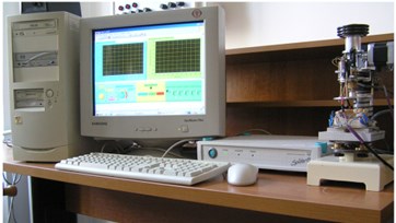
Laboratory measurements were performed on a specialised measurement set of own design (Fig. 5), which consists of the mechanical part used to apply static or kinematic loads as well as the electronic measuring part, which controls the measurement process and allows to archive and process the measurement results. At the same time, a custom method of measuring the quantities, which characterise the prosthesis operation that involves applying the force spread over the entire plane of the prosthesis, was offered.
Considering the accuracy of offset measurement by potentiometric transducers of linear displacements determined by the individual graduation from each transmitter, it was determined that the nonlinearity error any of them does not exceed 0.8 % (P0 → 0.74 %; P1 → 0.69%; P2 → 0.72 %; P3 → 0.76 %).
The definition of the relative movement error and prosthesis surface tension directly result from the measurement method which was assumed and described in the article, assuming that the variables used to determine the displacement and deformation are independent [29, 30]. The relative error of the measuring amplifier , defined on an experimental basis, does not exceed the value of 0,1 %.
Fig. 5Measurement set for testing of dental prostheses
Due to the use of the value differences indicated by the sensors to determine the offset value, the measurement error can be determined using the following formula:
The accuracy of the strain measurement is influenced both by the error from measuring amplifier and the accuracy of determining the constant k for strain gauges. The company Hottinger Baldwin Messtechnik gives in the data catalogue, that the error constant should not exceed the value of 0,5 %. Thus, due to the use of the difference of values indicated by the sensors to determine the strain, and the use of only one active strain gauge, the measurement error of this parameter can be determined from the following formula:
In Eq. (3) and (4) the arithmetic sum was used due to the lack of premises about the independence of the variables used for determination of variables such as displacement and strain.
3. Measurement method
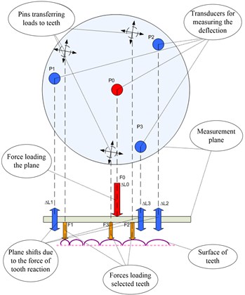
In the presented method, it was assumed that the upper parts of teeth clearly determine a plane, the position of which may change during the natural processes of chewing or biting. The replacement of natural teeth with artificial ones may result in a different reaction of artificial teeth to the natural ones, depending on the prosthesis design. Therefore, it is important to know how the position of the above mentioned plane changes, if teeth are restored with the prosthesis. The idea of measurement is shown in Fig. 6.
The force of the known value is applied to the centre of the measurement plane. It is transferred directly to selected teeth with the use of three pins. The location of pins is regulated in all three directions. It allows to precisely adjust the application of forces to three selected teeth. However, it is assumed that at least one of the selected teeth is an artificial tooth (a tooth of the alar cast partials). The measurement plane is intended to be rigid, i.e. it is not subject to deflection (deformation) and it only changes its position after applying the force according to the reaction of teeth. As a result, at measurement points P0-P3, there is a change of the position in a vertical plane -. The value of the position change is measured at the indicated points by the transducers of linear shifts. The measurement points P1-P3 (transducers of linear shifts) are arranged at the apexes of an equilateral triangle, and the P0 point is located exactly in the middle of this triangle. With the use of at least three points, it is possible to unambiguously determine a plane in the three-dimensional space. The values, determined in the measurement process, of initial indications of the measuring transducers as well as gains - resulting from the application of external force of the known value provide grounds for a further analysis of the obtained results.
Fig. 6The measurement method of deformation and stress of the dental prosthesis
4. Software
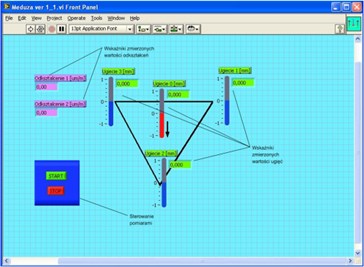
A computer with the Meduza ver1.1, which was developed for the purposes of this experiment and based on the LabVIEW software platform, controls the operation of the entire measurement system. The control of the Spider 8 measuring amplifier, as well as its configuration, triggering, and transmission of measurement results are executed by the RS-232C interface.
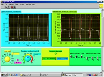
The software designed for the control of applying loads and parallel measurements performs many functions. It displays the recorded signals of shifts and deformation. However, the performance of this function is dependent on enabling the measurement channel. Disabling the channel results in no display of a given signal on the oscilloscope indicator. It allows to remotely select the control parameters of the measurement process. Virtual platforms for static and kinematic measurements are shown in Fig. 7.
Fig. 7The virtual control panel of static and kinematic measurements
5. Research results
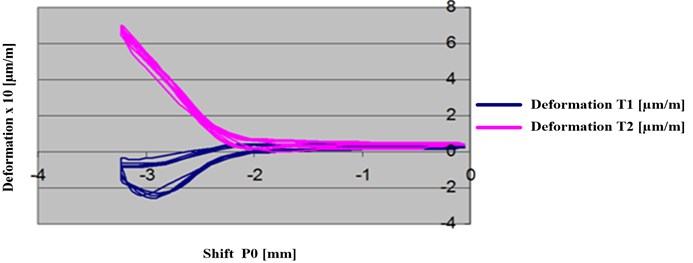
Exemplary measurements of the presented method are illustrated in Fig. 8 (static measurements) and Fig. 9 (kinematic measurements) by sequentially loading of selected teeth with the increasing force.
Fig. 8Shifts of points of the measurement plane for different load values
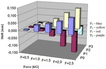
Fig. 9Deformation of the denture saddle in the shift function of the entire measurement plane. The load of 1 kG
6. Conclusions
The paper presented the issues related to the study of the actual alar cast partial. For this purpose, the functioning of this type of prostheses, with the particular emphasis on forces and stresses that occur there, were analysed. It allowed to prepare the measurement station, which makes it possible to measure the prosthesis model deformation under the influence of the dynamic load. The aspects related to the dynamics of the measurement system were also presented. In the further research, the experiments, which allow to visualise the shift and deformation signals as well as functional dependencies between the recorded values (using the computer assistance in the form of the LabVIEW software package), were conducted. The proposed method of distributed load forcing, contributed to the development of methods for quick verification assessment of the vertical stability of the prosthesis, thus verifying the correctness of one of the criteria for its implementation [31]. Stability is considered as the prevention of excessive movement of the prosthesis during the process of chewing. This objective requires ensuring the conditions, which are inherently contradictory.
Prevention of movement of the prosthesis can be ensured through stable (rigid) its attachment to the already existing teeth. Providing a rigid attachment can cause occurrence of large forces and moments at fixing points leading to the violation of the teeth, in which has been fixed prosthesis. Reducing these forces, in another extreme case, may lead to loss of comfort of using dentures. So it is necessary to ensure both of these conditions. Physicians-prosthetists use the only available method for rating the stability. It is a pain method, which is reported by the user. It should be remembered, that the dentures, in addition to the aesthetic function, should provide the patient to maintain the existing state of gingival, and the existing before using prosthesis, as long as possible. Both too excessive as well as too small pressures on the gums, during the chewing action of foods, cause quicker disappear of soft tissue in the mouth. Bad fitting of dentures on abutment teeth, or lack of stability of the prosthesis, causes quick shaking of these natural supports and, consequently, their falling out.
References
-
Kłaptocz B. Biomechanics of the Masticatory System. Propedeutyka Dentistry, PZWL, Warszawa, 1990.
-
Hupfauf L., Koeck B. Partial Prostheses. Kinematics Dentures. Urban and Partner, Wrocław, 1997.
-
Michalski W., Kuchta M., Fokow K., Chwaleba A. Load cell measurement of stresses the major connector at displacements of the wings the upper a skeletal denture in the experimental conditions, Part II. The rating decomposition of deformation and linear displacements for numerical simulation. Protet Stomatol, 2005, (in Polish).
-
Kuchta M., Chwaleba A., Gryszkiewicz M. Experimental verification of deflection backbone modeling dentures with separate kinematics. X School Computer-Aided Design, Manufacturing and Maintenance, Jurata, 2006, p. 91-97, (in Polish).
-
Kuchta M., Szulim M. Electronic measurement set for diagnostic dentures with dynamic excitations. Przeglad Elektrotechniczny – Electrical Review, Vol. 12B, 2011, p. 96-100, (in Polish).
-
Kuchta M., Siergiejczyk M., Pas J. FEM analysis of arch cast partials. Journal of Vibroengineering, Vol. 16, Issue 8, 2014, p. 4039-4044.
-
Kuchta M., Wnuk M. Modeling elastic support dentures. Electrical Review, Vol. 12, 2010, p. 79-82, (in Polish).
-
Henderson D., McGivney G. P., Castleberry D. J. McCracken’s Removable Partial Prosthodontics. C.V. Mosby Co. St. Louis, 1985.
-
Hupfauf L., Niedermeier W. Partial Dentures. Kinematics of Dentures. Urban and Partner, Wrocław 1997, (in Polish).
-
Michalski W, Michniowski Z., Kuchta M., Chwaleba A. Numerical simulation of mechanical behavior and reactions of the wing base of the upper denture – model flat. Protetyka Stomatologiczna – Prosthodontics, Vol. 3, 2005, p. 197-206, (in Polish).
-
Niedermeier W. For Storage Behavior Rigidly Supported Out Prostheses. Deutsche Zahnarztliche Zeitschrift, 1980.
-
Kydd W. L., Daly C. H., Wheeler J. B. The thickness measurement of masticatory mucosa in vivo. International Dental Journal, Vol. 21, Issue 4, 1972, p. 430-441.
-
Kuchta M., Kwiatos K., Fokow K. Set-up diagnostic tests dentures. Diagnostics, Vol. 3, Issue 39, 2006, p. 187-193, (in Polish).
-
Michalski W., Kuchta M., Fokow K. Tensometric experimental measurements of mechanical wing for the numerical simulation of dentures. Materials Conference VII Symposium on Modeling and Measurement in Medicine, Krynica, 2005, p. 197-203, (in Polish).
-
Burdzik R. Implementation of multidimensional identification of signal characteristics in the analysis of vibration properties of an automotive vehicle’s floor panel. Eksploatacja i Niezawodnosc – Maintenance and Reliability, Vol. 16, Issue 3, 2014, p. 439-445.
-
Burdzik R., Konieczny Ł. Application of vibroacoustic methods for monitoring and control of comfort and safety of passenger cars. Mechatronic Systems, Mechanics and Materials II, Solid State Phenomena, Vol. 210, 2014, p. 20-25.
-
Dabrowski T., Bednarek M., Fokow K., Wisnios M. The method of threshold-comparative diagnosing insensitive on disturbances of diagnostic signals. Przeglad Elektrotechniczny – Electrical Review, Vol. 88, Issue 11A, 2012.
-
Siergiejczyk M., Pas J., Rosiński A. Evaluation of Safety of Highway CCTV System’s Maintenance Process. The monograph „Telematics – support for transport”, Monographic Publishing Series – „Communications in Computer and Information Science”, Vol. 471, Springer-Verlag, Berlin, Heidelberg, 2014.
-
Siergiejczyk M., Pas J., Rosinski A. Train call recorder and electromagnetic interference. Diagnostyka, Vol. 16, Issue 1, 2015, p. 19-22, (in Polish).
-
Kuminek T., Aniołek K., Młyńczak J. A numerical analysis of the contact stress distribution and physical modelling of abrasive wear in the tram wheel-frog system. Wear, Vol. 328, 2015, p. 177-185, (in Polish).
-
Młyńczak J. Algorithm Determining the Setting Force at Point Machines. Telematics – Support for Transport. Book Series: Communications in Computer and Information Science, Vol. 471, Springer, Heidelberg, 2014, p. 321-330, (in Polish).
-
Rosinski A. Reliability-Exploitation Analysis of Power Supply in Transport Telematics System. The Monograph Safety and Reliability: Methodology and Applications – Proceedings of the European Safety and Reliability Conference ESREL, CRC Press/Balkema, London, 2015, p. 343-347.
-
Rosinski A., Dabrowski T. Modelling reliability of uninterruptible power supply units. Eksploatacja i Niezawodnosc – Maintenance and Reliability, Vol. 15, Issue 4, 2013, p. 409-413.
-
Duer S., Zajkowski K., Duer R., Pas J. Designing of an effective structure of system for the maintenance of a technical object with the using information from an artificial neural network. Neural Computing and Applications, Vol. 23, Issues 3-4, 2013, p. 913-925.
-
Pas J., Duer S. Determination of the impact indicators of electromagnetic interferences on computer information systems. Neural Computing and Applications, Vol. 23, Issues 7-8, 2013, p. 2143-2157.
-
Mazurek J. Fundamentals of Automatics. PWN, Warszawa, 1996.
-
Osowski S. The Outline of Bill of Operator Theory and Applications in Electrotechnics. WNT, Warszawa, 1981.
-
Gajda J., Soroka R. Measurement of the Phase Angle. Methods-Layouts-Algorithms, AGH, Kraków 2000.
-
Kulas-Jęcek B., Kuśmirek Z. Standards of Electrical and Evaluation of Measurement Uncertainty. WPŁ, 2006.
-
Taylor J. R. Introduction to the Error Analysis. PWN, Warszawa, 1995.
-
Kuchta M., Szulim M., Fokow K., Sokołowski Z. The method of assigning stability of the wing dental prosthesis. Przegląd Elektrotechniczny, Vol. 5, 2008, p. 335-338, (in Polish).
