Abstract
The class of vehicles that can move both in the air and underwater has been of great interest for decades. A novel water-air unmanned vehicle with double quadrotor structure is designed in this study. The air power mechanism works when the vehicle flies in the air, whereas the water power mechanism works when it moves underwater. The water entry process of water-air unmanned vehicle requires accurate attitude and height control, or the vehicle may bounce off or overturn. However, a force resisting its descent known as in-ground effect will affect its stability. The in-ground effect formula of the water entry process is derived by experiments, and the water entry dynamic model is improved at the same time. An active disturbance rejection controller (ADRC) is designed for the control of water entry attitude and height. Experimental results obtained from the comparison of the ADRC and a proportional-integral-derivative (PID) controller show that the ADRC designed in this study is more robust than the PID controller for the internal coupling and external disturbance on the vehicle. Moreover, the ADRC can meet the requirements of rapid attitude adjustment and accurate height control.
1. Introduction
The development of water-air unmanned vehicle capable of flying in the air and moving underwater has become one of the most popular topics because of its wide application in the military and civil services [1]. The water-air unmanned vehicle with quadrotor structure [2], which has strong mobility, can take off and land vertically in a narrow space, fly free in all directions, and hover easily in the air or move underwater.
The motion environment switch of this kind vehicle requires accurate attitude and height conditions, particularly from air to water. If the vehicle crosses the water surface with improper attitude, then it may bounce off or overturn [3], and normal motion cannot be guaranteed after it enters the water.
When the water-air unmanned vehicle descends until it reaches a certain height from the water surface, the lift increases and the drag decreases, leading to the rapid increase of the lift-to-drag ratio, which is called the in-ground effect (IGE) [4]. The IGE can improve the aerodynamic efficiency of the vehicle, but can adversely affect the stability. Several researchers have investigated the IGE of rotors from the experimental and theoretical aspects. I.C. Cheeseman and W.E. Bennett [5] proposed a computational model to calculate the IGE of helicopter rotors based on the image method and pointed out that the ratio of thrust produced by a single rotor with and without the IGE is a function related to the rotor radius and the vertical distance from the disk to the ground. H. H. Heyson [6] conducted an experiment on the induced velocity of the aircraft during vertical takeoff and landing and observed the air flow change when the aircraft was 0.3-2 times of the rotor height above the ground surface. The results show that, when the height of the aircraft from the ground surface is the same as the length of its wing, the thrust decreases by 20 % under the influence of IGE. With the development of computer science, many researchers have applied computational fluid dynamics (CFD) to analyze the air flow around the rotor, which is important in investigating the IGE of aircrafts. Ye et al. [7] developed a numerical simulation method of IGE for helicopters based on the unstructured embedded grid method, simulated the IGE with one surface of the background embedded mesh, and calculated the location of the blade-tip vortex and the rotor thrust increment in the IGE condition. Zhao and He [8] developed a viscous discrete vortex method based on the Lagrange description and simulated the flow field of the hovering IGE of the CH-53E class helicopter. However, when the CFD method is used to calculate the rotor flow filed under the complex IGE condition, the result and its accuracy must be improved to avoid the limitations of numerical dissipation and grid quality.
At present, the studies related to rotor IGE are mainly focused on single-rotor aircrafts. Significant differences exist between the flow fields of single-rotor aircraft and that of water-air unmanned vehicle with double quadrotor structure. Qi [9] simulated the flow field characteristics of a normal quadrotor aircraft without IGE using the finite element method. The results show strong turbulence among the four rotors, and the distribution of the flow field around the aircraft is complex and widely affected. T. Ran and H. J. Kim [10] developed a special device to analyze the IGE of quadrotor aircraft, but the formula obtained is excessively complex to be applied directly. Otherwise, the large difference in the physical properties between water and ground surfaces will result in the difficulty in determining the IGE of water-air unmanned vehicle because of the deformation of the water surface when the vehicle approaches it.
The IGE will result in obvious differences in the dynamic model of the water-air unmanned vehicle. Various methods are used to control the flight of the quadrotor aircraft in air, such as proportional-integral-derivative (PID) control [11], backstepping control [12], sliding mode control [13], and robust control [14]. However, the aforementioned studies did not consider IGE, which cannot be ignored when an aircraft flies at super low attitude particularly or when landing. The water-air unmanned vehicle with quadrotor structure has the characteristics of underactuated system, strong coupling, and sensitivity to disturbance, and it requires stricter control than the normal quadrotor aircraft because of its special mission and motion environment (water and air). The active disturbance rejection control method [15] can ensure attitude control and height control of the water-air unmanned vehicle by estimating and compensating external and internal disturbances acting on the system in real time.
In this study, a water-air unmanned vehicle with double quadrotor structure is designed, and the IGE formula is obtained through experiments based on the method of Li [16], which improves the dynamic model of the water entry process. An active disturbance rejection controller (ADRC) is designed to achieve effective control of the water entry process of the vehicle. The remainder of this paper is organized as follows: In Section 2, the mechanical structure, operation principle, and basic dynamic model of the water-air unmanned vehicle with double quadrotor structure are introduced. In Section 3, the IGE formula of water entry is obtained through the experimental method. In Section 4, a control system structure based on ADRC is given, and the parameter tuning methods of the ADRC are analyzed and summarized. In Section 5, the robustness and effectiveness of the ADRC are verified through a comparison with a normal PID controller. The conclusion is given in Section 6.
2. Structure and dynamic model of the water-air unmanned vehicle
2.1. Structural description of the water-air unmanned vehicle
The water-air unmanned vehicle with double quadrotor structure mainly consists of double-layer body frame, control box, motor, air power mechanism, and water power mechanism. The core component is the control box, inside of which is installed with control system, batteries, and other components. The control system is a dual processor structure. One of them is for management mission, and the other one is to calculate the attitude and control law. The hardware of the control system is shown in Fig. 1.
Carbon fiber is selected for the body frame to improve the intensity and reduce the weight. When the vehicle works, the motor is driven by a 12 V direct current battery found inside the control box and the maximum rotation speed is approximately 9,000 r/min. The 1050 real carbon fiber propeller and two-stroke D50 underwater propeller are selected as the air power mechanism and water power mechanism, respectively. The control box is cuboid, which is simply processed and installed but increases the drag to a certain extent when the vehicle moves.
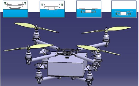
When the water-air unmanned vehicle flies in the air, only the air power mechanism works. By contrast, when water-air unmanned vehicle moves underwater, only the water power mechanism works. On the upper surface of the body frame, a turntable is installed. The propeller arms are folded at ordinary time to save space for easy storage. When the vehicle starts to fly, the propeller arms are unfolded and the air power mechanism starts to work. When the vehicle crosses the water surface, the switch between the air and water power mechanisms is achieved by the cooperation of pressure sensor and operator observation. The water entry process of the vehicle should meet certain conditions. The vehicle enters the water vertically because its attitudes in air and underwater are almost the same. In other words, the body of the vehicle should be kept stable in the water entry process (the attitude angle is 0). The design sketch and motion principle of the water-air unmanned vehicle are shown in Fig. 2.
Fig. 1The hardware of control system
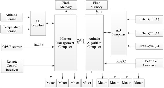
Fig. 2The design sketch and motion principle of the water-air unmanned vehicle
2.2. Dynamic model
The major focus of this study is the force of the water-air unmanned vehicle before it enters the water, and the dynamic model of the vehicle flying in air is established. The dynamic model of the normal quadrotor aircraft is given in the literature, and the following is a simple description:
Establish the ground coordinate system E:{xe,ye,ze} and the body coordinate system B:{xb,yb,zb} based on the right-hand principle, as shown in Fig. 3.
Fig. 3Body coordinate system and ground coordinate system
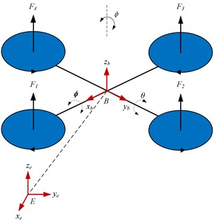
(x,y,z) are the location coordinates of the body coordinate system, and (ϕ,θ,ψ) are three Euler angles (roll angle, pitch angle, and yaw angle). The model can be divided into the linear motion subsystem and angular motion subsystem, which are shown as follows:
The transformation matrix from the body coordinate system to the ground coordinate system is shown as follows:
Linear motion dynamic model can be expressed as follows:
where, ˙ξ and V are the velocity vector in the ground and body coordinate systems, respectively.
Angular motion dynamic model can be expressed as follows:
where ˙η and ω are the angular velocity vector in the ground and body coordinate systems, respectively.
The six degrees of freedom movement of the normal quadrotor aircraft includes three directions of angular movement and three directions of linear movement. When the aircraft flies in high height, the formula of the linear motion is based on the Newton-Euler formula, as follows:
where m is the mass of the quadrotor aircraft, g is the acceleration due to gravity, ez=(0,0,1)T is the unit vector in the ground coordinate system, and uT is the total lift produced by four rotors, as follows:
where Ωi and Fi are the rotating speed and the lift produced by the ith rotor, respectively, and b is the lift coefficient.
The dynamic model of the angular motion can be expressed as follows:
where I is inertia matrix, -ω×Iω and Gaare the gyroscopic effect produced by rigid body rotation and the direction change of the propeller, respectively, and τ is the control moment, as follows:
where, Jr is the rotational inertia, l is the distance from motor to the gravity center and d is the drag coefficient.
According to Eqs. (7) and (9), the dynamic model of linear motion and angular motion are as follows respectively:
Therefore, quadrotor aircraft is typically under actuated system with 4 input of (uT,τϕ,τθ,τΨ) and 6 output of (x,y,z,ϕ,θ,Ψ). The complete dynamic model is shown as follows:
where:
The expression of control input is as follows:
2.3. IGE
I. C. Cheeseman [5] proposed a general model of the IGE of helicopters, which is shown as follows:
where r is the radius of the propeller, z is the distance from the propeller to the ground, TOGE is the thrust produced by the propeller without IGE, and TIGE is the total thrust IGE. The previously presented theoretical formula is applied to a single-rotor helicopter. For the large difference between helicopter and quadrotor aircraft, the formula cannot be used directly in calculating the IGE of the quadrotor. According to the IGE formula of a normal quadrotor [16], we introduce a correct coefficient based on Eq. (17) that can be applied to the water-air unmanned vehicle with double quadrotor structure, as shown in Eq. (18):
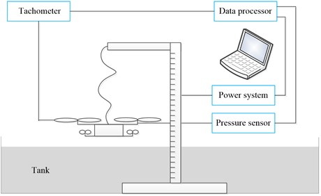
where TINPUT is the required thrust, TOUTPUT is the real thrust produced by the vehicle, rr is the propeller radius of the water–air unmanned vehicle, zr is the distance from the vehicle to the water surface, and α is a coefficient that must be determined. α is determined by experiments. The experimental setup is shown in Fig. 4, and mainly functions of each part are introduced.
Fig. 4IGE experimental setup
(1) Power system.
The power system provides the motor power, which consists of DC power supply, brushless motor and speed governor. The rated voltage of the supply is 15 V and the rotor is inner rotor brushless motor.
(2) Operation system.
The operation system adjusts the input current of the bruthless DC motor by changing the duty cycle of PWM control pulse, which can realise the control of motor rotor speed.
(3) Measurement system.
The measurement system is used to measure the speed, thrust and power consumption of the rotor wings. Tachometer is used to measure the speed. Press sensor is applied to measure the thrust and its precision is –0.019 V/10 g. The power consumption is obtained by processing the recorded data of voltage and current.
(4) Fixing equipments.
The fixing equipments are fixed at the bottom of the tank which can support the power system. The trestle has a scale which is convenient for reading out the hovering height of the water-air vehicle.
The calculation steps are as follows:
Step 1. Determine the input thrust TINPUT of the vehicle at different heights from the water surface. Typically, these values can be obtained directly. Table 1. shows the relationship between the height where the water-air unmanned vehicle hovers and the thrust it requires.
Table 1The height the water-air unmanned vehicle hovering and the thrust it required
Altitude (m) | 0.16 | 0.19 | 0.24 | 0.30 | 0.34 | 0.39 | 0.43 | 0.47 |
Thrust (N) | 22.73 | 23.09 | 23.75 | 24.25 | 24.70 | 25.0 | 25.07 | 25.16 |
Step 2. Determine the real thrust TOUTPUT at different heights from the water surface. Under the condition that the vehicle is steadily hovering, the thrust it produces is equal to its gravity, that is, TOUTPUT=mg, and TOUTPUT can be regarded as a constant.
Step 3. Fit the value of α through the least square method.
The rr and m of the water-air unmanned vehicle designed in this study are 0.15 m and 2.57 kg, respectively. In the range of 0.15 m <zr< 0.5 m, α should be a fitting formula, which can be expressed as:
Fig. 5IGE curve of water-air vehicle
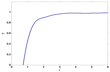
Fig. 6Change of water surface
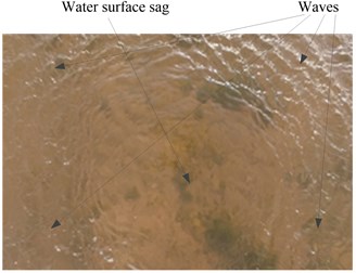
The experiments are conducted in an indoor pool, which can reduce the influence of the wind and waves in natural waters. We assume that the dimensional factors are T=TINPUT/TOUTPUT and r=zr/rr, and a smaller T indicates a more obvious IGE. When T= 1, the IGE can be ignored. Fig. 5. shows that, when r= 3.3, the IGE of the water-air unmanned vehicle is still obvious, and thereafter, the thrust changes gradually. I. C. Cheeseman [5] pointed out that the significant interval of the IGE of a single rotor is 0.5 <r<2. Li [16] pointed out that the significant interval of the IGE of the normal quadrotor aircraft is 0.5 <r< 4. In this study, the significant interval of the water-air unmanned vehicle is 0.5 <r< 3.3 in the water entry process because, when the vehicle approaches the water surface gradually, it will cause a series of complex disturbances on the still water surface. Part of the air flow between air propellers and the water surface is lost in random directions. As a result, the significant interval of the IGE of the water-air unmanned vehicle in the water entry process is larger than that of the single-rotor helicopter but smaller than that of the normal quadrotor aircraft. Fig. 6. shows the changes of the water surface when zr= 0.25 m. It can be seen that when the water-air unmanned vehicle approaches to the water surface, below it, the water sags. At the same time, waves spread around.
3. Design of the ADRC
In achieving accurate height control of the water-air unmanned vehicle, the IGE is considered in the previously presented dynamic model. The height dynamic formula is shown as follows:
The dynamic model of the water-air unmanned vehicle shows that the intercoupling problem of attitude control including roll, pitch, and yaw can be solved well by the ADRC method. The system chart of height and attitude control of the vehicle is shown in Fig. 7.
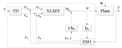
The ADRC consists of the tracking differentiator (TD), extended state observer (ESO), and nonlinear state error feedback (NLSEF), which is shown in Fig. 8.
According to the separation principle, with the pitch channel as an example, TD, ESO, and NLSEF are designed, and the discrete form of the control algorithm and the regular parameter settings are given.
Fig. 7System chart of the vehicle height and attitude control
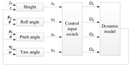
Fig. 8Active disturbance rejection controller
3.1. Tracking differentiator
where, defined fst() as follows [17]:
where:
θd is the target pitch angle, v(k) is the input signal at time k, T is the integral step of the tracking differentiator, r is the velocity factor, and h is the filtering factor. According to engineering practice, a larger r indicates a shorter transient process and a closer distance to the input signal. A smaller r indicates a longer transient process, which influences the response rate of the system. A larger h indicates a better filtering result, and the phase loss of the tracking signal is larger. In practical application, h=3T-7T.
3.2. Extended state observer
The definition of fal() is as follows:
The extended state observer is the core of the ADRC, which directly affects the control result. The nonlinear shape of fal() is determined by α. The linear interval width of fal() near the origin is determined by δ. If δ is excessively large, then the approximation capability of the nonlinear signal will weaken. If δ is excessively small, then it will cause high-frequency chattering. β1, β2, and β3 are feedback gains of state error, which affect the convergence velocity of ESO.
3.3. Nonlinear state error feedback
k1 and k2 are controller gains. The larger the value of k1, the sooner the system responds. The largeness of k1 may cause divergence of the output. The appropriate increase of k2 can improve the dynamic performance of the system and restrain overshoots in the transient process. b is the compensation factor, which determines the variation range of the estimated value of the disturbance.
3.4. Stability condition of ADRC
In an ADRC system, the role of TD and NLSEF is to accelerate response, and the system stability mainly depends upon ESO [18, 19].
For the second order discrete-time ESO proposed in this paper, when α1=α2=1, the ESO is linear. That is:
Characteristic equation of the second order discrete-time ESO is:
Assume z=ω+1/ω-1, and transform D(z) to D(ω). According to the Routh stability criterion, the stability condition of a linear second order discrete-time ESO is:
For a nonlinear second order discrete-time ESO, if (α1,α2,β1,β2) is determined:
That is the stability condition of ESO.
4. Analysis of the experimental results
An experiment comparing the ADRC and the normal PID controller is conducted to verify the superiority of the ADRC in attitude and height control of the water-air unmanned vehicle during water entry. The parameters of the model are shown in Table 2. The control parameters are determined by several experiments based on the previous regular tuning and are shown in Table 3.
Table 2Parameters of the water-air vehicle
Parameter | Value | Unit |
m | 2.57 | kg |
l | 0.32 | M |
g | 9.8 | m∙s-2 |
b | 4.32×10⁻⁵ | m∙s-2 |
d | 2.5×10⁻⁶ | N∙s-2 |
Ixx | 8.1×10⁻³ | N∙m∙s-2 |
Iyy | 8.1×10⁻³ | N∙m∙s-2 |
Izz | 14.2×10⁻³ | N∙m∙s-2 |
Jr | 6×10⁻⁵ | kg∙m2 |
Table 3Parameters of ADRC
Parameter | Roll channel controller | Pitch channel controller | Yaw channel controller | Height controller | |
TD | r | 2 | 2 | 2 | 2 |
h | 0.06 | 0.06 | 0.06 | 0.06 | |
ESO | α1 | 0.5 | 0.5 | 0.5 | 0.5 |
α2 | 0.25 | 0.25 | 0.25 | 0.25 | |
δ | 0.1 | 0.1 | 0.06 | 0.06 | |
β1 | 90 | 90 | 90 | 90 | |
β2 | 450 | 450 | 550 | 580 | |
β3 | 2600 | 2600 | 3200 | 3000 | |
NLSEF | α1 | 0.5 | 0.5 | 0.5 | 0.5 |
α2 | 1.5 | 1.5 | 1.5 | 1.5 | |
k1 | 50 | 50 | 80 | 120 | |
k2 | 30 | 30 | 75 | 100 | |
b | 123 | 123 | 80 | 100 |
4.1. Experiment on attitude control
The chief flow chart of attitude control system and program flow chart of attitude control algorithm are shown in Fig. 9. and Fig. 10., respectively.
The initial roll angle of the water-air unmanned vehicle is ϕ0=−0.13 rad, the pitch angle is θ0= 0.038 rad, the yaw angle is ψ0=0.074 rad, and all desired attitude angles are 0 rad, which is the stable hovering state. Under the control of the ADRC and the normal PID controller, the change curves of the attitude angle are shown as follows.
Fig. 9Chief flow chart of attitude control system

Fig. 10Program flow chart of attitude control algorithm
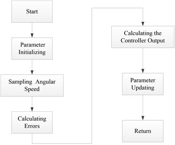
Fig. 11. shows that the attitude response curve of the ADRC can track the desired value well. Although the PID controller can also track the desired value, a large oscillation exists and a long setting time is needed. The performance indices of the ADRC and the normal PID controller are shown in Table 4. With the roll angle ϕ control as an example, the overshoot of the PID controller is 35 %, approximately four times more than that of the ADRC, which is 7.2 %. The advantage of ADRC in setting time is obvious in the water entry process of the water-air unmanned vehicle. Similar conclusions on the control of pitch angle θ and yaw ψ angle are obtained. The main reason for the aforementioned results is that a coupling interference exists in the attitude angle control channels, and this interference can be regarded as internal disturbance. ESO has the abilities to estimate and compensate, which enhance the robustness of the system significantly.
Fig. 11Attitude angle change curves of PID controller and ADRC
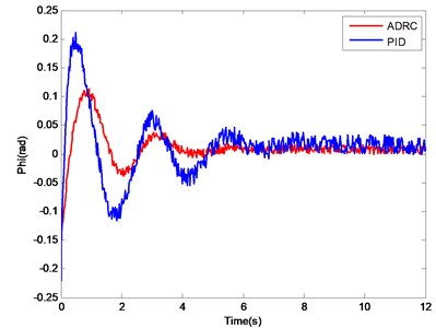
a) Change curve of roll angle
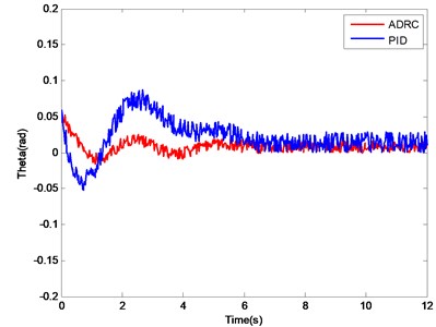
b) Change curve of pitch angle
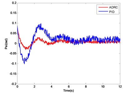
c) Change curve of yaw angle
Table 4Performance Index of ADRC controller and normal PID controller
Variable | Normal PID controller | ADRC | ||
Overshoot / % | Setting time / s | Overshoot / % | Setting time / s | |
ϕ (Phi) | 35 | 7.3 | 7.2 | 4.2 |
θ (Theta) | 27 | 7.4 | 6.2 | 4.1 |
ψ (Psi) | 25 | 8.2 | 6.5 | 4.5 |
4.2. Experiment on height control
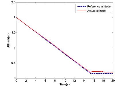
The initial height of the water-air unmanned vehicle is 2 m. When the vehicle hovers steadily at such height, the water entry order starts. Given the double-layer structure and body frame of the water-air unmanned vehicle, when its bottom touches the water, the air rotor is 0.15 m high from the water surface. The curves of the UAV height changing under the control of the PID controller and the ADRC are shown in Figs. 12. and 13.
Fig. 12. shows that, at the early stage of the descent of the vehicle, the tracking trajectory of the PID controller coincides well with the reference trajectory. However, when the height is lower than 0.5 m, the PID controller cannot track it effectively because of the increase of IGE. The maximum error is more than 0.3 m, and the root mean square error is 0.14 m. Fig. 13. shows that the tracking trajectory of the ADRC coincides well with the reference trajectory at the early stage of the descent or approach of the UAV to the water surface. In the experiment, the real descending height is 0.17 m, which is close to the theoretical value. The maximum error is 0.06 m, and the root mean square error is 0.03 m. The IGE can be regarded as an external interference, and the ADRC method can deal with such a problem.
Fig. 12Change curves of height under PID controller
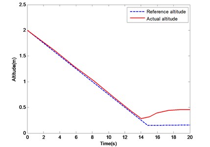
Fig. 13Change curves of height under ADRC controller
5. Conclusions
A water-air unmanned vehicle with double quadrotor structure is proposed in this study. The IGE formula of water entry is derived by the experimental method, and the dynamic model is improved at the same time. An ADRC is designed, and the parameter setting of the controller is completed by practical experience. Experiments on the water entry attitude and height control of the water-air unmanned vehicle are conducted. The results show that, compared with the PID method, the ADRC has better stability, shorter setting time, and stronger robustness.
References
-
Zhao W. D., Liu J. H., Liang J. H., Wang T. M., Yang X. B., Yao G. C. The application of CAD technology in the process of aircraft bionic design. Journal of Graphics, Vol. 35, Issue 2, 2014, p. 243-249.
-
Li X. S. The USA Develops a New Water-Air Vehicle. http://tech.huanqiu.com/diginews/2015-12/8247487.html, 2015.
-
Wang Y. H. Dynamic Response Analysis of Airborne Torpedo and Deep-mine during Water-Entry Impact and Research of the Relative Technology. Northwestern Polytechnical University, 2008.
-
Hayden J. S. The effect of the ground on helicopter hovering power required. Proceedings of the 32nd American Helicopter Society Forum, Washington, D.C., 1976, p. 10-12.
-
Cheeseman I. C., Bennett W. E. The Effect of Ground on a Helicopter Rotor in Forward flight. Technical Report, Aeronautical Research Council, 1957.
-
Heyson H. H. Theoretical Study of the Effect of Ground Proximity on the Induced Efficiency of Helicopter Rotors. http://ntrs.nasa.gov/archive/nasa/casi.ntrs.nasa.gov/19770017115.pdf, 1977.
-
Ye L., Zhao Q. J., Xu G. H. Numerical simulation on flowfield of rotor in ground effect based on unstructured embedded grid method. ACTA Aeronautica et Astronaut ICA Sinica, Vol. 30, Issue 5, 2009, p. 780-786.
-
Zhao J. G., He C. J. A viscous vortex particle model for rotor wake and interference analysis. Journal of American Helicopter Society, Vol. 55, Issue 1, 2010, p. 1-14.
-
Qi S. H. The Design and Attitude Control of a Micro Quadrotor Aircraft. Shanghai Jiao Tong University, 2013.
-
Ryan T., Kim H. J. Modeling of quadrotor ground effect forces via simple visual feedback and support vector regression. Proceedings of the AIAA Guidance, Navigation, and Control Conference, 2012.
-
Hoffmann G. M., Huang H., Waslander S. L., et al. Quadrotor helicopter flight dynamics and control: theory and experiment. Proceedings of the AIAA Guidance, Navigation, and Control Conference and Exhibit, 2007.
-
Abhijit D., Frank L., Kamesh S. Backstepping approach for controlling a quadrotor using Lagrange form dynamics. Journal of Intelligent Robots and Systems, Vol. 56, 2009, p. 127-151.
-
Lee D., Kim H. J., Sastry S. Feedback linearization vs. adaptive sliding mode control for a quadrotor helicopter. International Journal of Control, Automation, and Systems, Vol. 7, Issue 3, 2009, p. 419-428.
-
Bai Y. Q., Liu H., Shi Z. Y., Zhong Y. S. Robust flight control of quadrotor unmanned air vehicles. Robot, Vol. 34, Issue 5, 2012, p. 519-524.
-
Wang J. S., Ma H. X., Cai W. L., et al. Research on micro quadrotor control based on ADRC. Journal of Projectiles, Rockets, Missiles and Guidance, Vol. 28, Issue 3, 2008, p. 31-40.
-
Li D. J., Zhou Y., Shi Z. Y., Lu G. Autonomous landing of quadrotor based on ground effect modeling. Proceedings of the 34th Chinese Control Conference, 2015, p. 5647-5652.
-
Han J. Q. Auto-disturbances-rejection controller and its application. Control and Decision, Vol. 13, Issue 1, 1998, p. 19-23.
-
Wang Y. H., Yao Y., Ma K. M. Error estimation of second order extended state observer. Journal of Jilin University (Engineering and Technology Edition). Vol. 40, Issue 1, 2010, p. 143-147.
-
Lei Z. L., Guo C., Fan Y. S. Dynamic positioning system based on active disturbance rejection technology. Journal of Ocean University of China, Vol. 14, Issue 4, 2015, p. 636-644.

