Abstract
In this paper, an experiment for decoupling the dynamic behavior of the levitation chassis of maglev vehicle with four electromagnetic suspension (EMS) modules is implemented, which validated that the stable suspension of maglev vehicle can be achieved by controlling individual EMS modules. Then, a dynamic model for single EMS module is established. A PD controller is designed to control the vertical position of the maglev vehicle. Simulations illustrate that the robustness of the controller is weak against the periodic disturbance. To improve the robustness of the controller, a nonlinear control law for disturbance rejection is applied by combining with a periodic disturbance estimator with an adaptive notch filter, which is capable of compensating exogenous nonlinear periodic disturbance. Different from using the existing control laws, the structure, parameters and period of the disturbance is not required. Moreover, the controller designed in this work satisfies the requirement of unidirectional force input. Simulation results are presented to demonstrate the excellent dynamic performance with the proposed robust controller.
1. Introduction
As a new type of urban rail transit, the low-speed maglev is becoming more and more popular owing to its low operating noise, small turning radius, strong climbing ability as well as minimum maintenance costs [1-4]. Meanwhile, the electromagnetic suspension (EMS) system has been widely installed in maglev passenger trains, magnetic bearings [5], bearing less motors [6], and etc. The primary task of the EMS system is to eliminate the influence of gravity via electromagnetic forces, which avoids contacts, and thus, no friction. Due to its technological tractability, riding comfort and environmental friendliness, maglev vehicles have broad applications and development prospects in intercity and urban transit systems. The EMS module system control is one of the key components of the maglev vehicle. A significant amount of research work has been conducted in this area to grantee the dynamic performance of the EMS system. Unfortunately, EMS system suffers from various control complexities such as: 1) open-loop instability; 2) essential strong nonlinearity; 3) a unidirectional control force input; 4) exogenous disturbance, which brought challenges to the control method.
To overcome the challenges brought by 1)-3), researchers proposed various control strategies in the past. For example, Kim et al. [7] proposed a considerably detailed dynamic modeling technique to accurately predict the air gaps of the magnetic train under consideration. Sun et al. [4] put the vibration information of the guideway into the designed controller, and presented a novel controller to effectively eliminate the coupling vibration. The method maintains system stability and reduces the exacting requirements of system stability on the guideway properties. Therefore, the construction cost is reduced drastically. Mohamed et al. [8] demonstrated that the Q parameterization theory can be employed to auto balance the rotor of an active magnetic bearing system. Recently, much effort has been directed toward the area of the disturbance rejection within magnetic suspension systems. Rodrigues et al. [9] presented an inter-connection passivity-based control law to yield a smooth stabilizing control law of the active magnetic bearing system. Behal et al. [10] proposed a linear, bounded-input and bounded-output filter to help the employment of the standard adaptive methods that compensated for an uncertain disturbance signal. Similarly, Xian et al. [11] designed an adaptive disturbance rejection method for unknown systems using a state estimate observer in a back-stepping method to realize the asymptotic disturbance rejection.
In this paper, a test for the vertical decoupling performance is implemented to validate that the stable suspension of the low-speed maglev vehicle can be realized by independent single EMS module control. Then, the dynamic equations for single EMS module is built and a robust position controller for disturbance rejection is presented by fusing a periodic disturbance estimator with adaptive notch filter, which is capable of compensating for the nonlinear, periodic and exogenous disturbance. Differing from the previous controller, the proposed controller only requires the disturbance to be bounded. Simulation results are included to illustrate the dynamic performance of the nonlinear controller.
2. Dynamic decoupling of levitation chassis
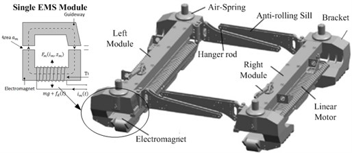
The maglev vehicle is composed of several identical levitation chassis. Every identical levitation chassis has distributed magnetic forces and four identical levitating controllers (i.e., EMS module) as shown in Fig. 2. In most of the literatures, the scholars simplify the maglev vehicle levitation control into single EMS module control [12-14], which means vertical decoupling of the EMS modules. Unfortunately, there are few experimental investigations for the reason of the simplification.
In order to simplify the whole maglev vehicle suspension control into single EMS module suspension control, the structure of the levitation chassis must be decoupled. The experiment for the vertical decoupling performance of the EMS modules should be implemented.
2.1. Structure of the maglev vehicle and levitation chassis
The maglev vehicles shown in Fig. 1 employ the distributed structure [15]. The vehicle body includes two parts, the carriage and the levitation chassis. Each carriage is supported by 3-4 identical but independently controlled levitation chassis. The levitation chassis and the carriage are connected by an air spring, while the levitation chassis is connected with the rail through electromagnetic forces. The physical structure of the levitation chassis is shown in Fig. 2. Each levitation chassis is constructed by suspension beams containing one set of linear motors and two sets of suspension magnet system in both sides coupling with the anti-roll module. 4 electromagnetic suspension (EMS) modules are connected to the levitation chassis.
Fig. 1Structure of the maglev vehicle
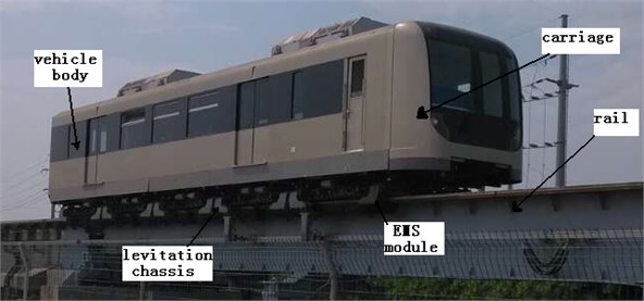
Fig. 2Structure of the maglev levitation chassis
2.2. Decoupling performance of EMS modules
The dynamic models of the levitation chassis are illustrated in Figs. 3-4. Because the structure of the chassis frame is the same in both left-right and front-back sides, Fig. 3 illustrates the force of the front of the chassis and Fig. 4, the right of the chassis.
Fig. 3Dynamic model-the front of the chassis
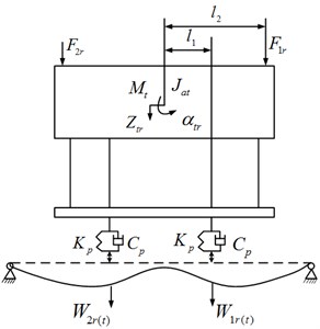
Fig. 4Dynamic model-the right of the chassis
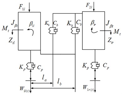
According to Figs. 3-4, the dynamics of the chassis can be expressed by the following expression:
where, X, ˙X, ¨X denote generalized displacement, velocity and accelerate respectively in the following manner:
¨X=[¨ztl,¨αtl,¨βtl,¨ztr,¨αtr,¨βtr]T,
and M, C, K are the mass matrix, damping matrix and stiffness matrix, respectively:
P denotes the generalized load matrix in the following manner:
where, Kp, Kβ, Cp and Cβ denote vertical stiffness, rolling stiffness, vertical damping and magnetic force damping respectively; Fl1, Fl2, Fr1 and Fr2 represent vertical forces from air springs of left front, left rear, right front and right rear to the chassis respectively; Wl1, Wl2, Wr1 and Wr2 represent the electromagnetic forces of left front, left rear, right front and right rear the corresponding track irregularity; ztl, ztr, βtl, βtr, αtl and αtr, denote heaving displacement, rolling angle and pitching angle of left and right of the chassis.
In order to achieve decoupling of the EMS modules, the levitation chassis must be independent of each side in structure. That is, one side of the levitation chassis with disturbance is displaced and the other side will not be affected and keep independent. According to the Eq. (1), the interaction between the right and left module is only about the rolling motion. The disturbance of FLOAD=50*time(N) is applied to the EMS module of the right levitation chassis to observe the simulation result of the left module which is shown in Fig. 5.
Fig. 5Simulation result of the left module
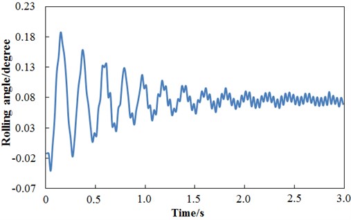
As shown in Fig. 5, the vibration of the left module lasts for 1.5 seconds and becomes steady state vibration where the maximum amplitude is 0.08 degree which is quite small. It declares that the stability of the right and left modules is mutual independent, which meets the requirements of decoupling for the levitation chassis.
The Fig. 6 illustrates the relationship between the displacement of the four displacement measuring points in Fig. 7 and the external disturbance force.
Fig. 6The simulation results of displacement
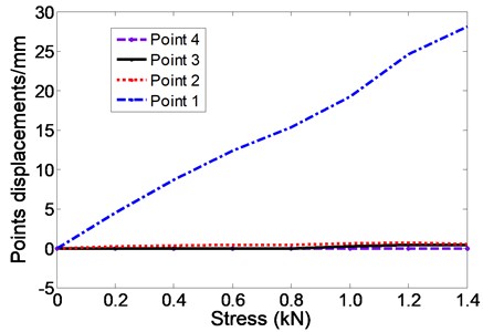
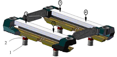
The hydraulic jacks and sensors are added to the levitation chassis which is illustrated in Fig. 7. The fulcrum of the jack in the Fig. 7 is named fulcrum 1. The locations of the four displacement sensors are named point 1, 2, 3 and 4 respectively in Fig. 7. Then, one of the four corners will be lifted up from 0 mm to 25 mm and the data of the displacement of the levitation chassis and the pressure can be obtained. The four variations of the displacements and the forces can be collected by lifting up the four jacks one by one. Thus, the decoupling capacity of the levitation chassis can be obtained.
Fig. 7Configuration of the test platform. 1 – jack, 2 – pressure sensor, (1)-(2) – displacement sensor
The value of the loads and displacements are recorded and listed in Table 1. According to Table 1, when fulcrum 1 is lifted up, the value of the diagonal fulcrum’s stress changes with the value of the fulcrum’s load and the values of the neighboring fulcrums are also in accordance. The displacement of fulcrum 1 is large while the other three fulcrums are very small, which can meet the decoupling requirements. Fig. 8 depicts the displacement of every point when fulcrum 1 is lifted up. The results for the other three fulcrums are exactly similar.
Table 1The vertical displacement
No. | Stress (kN) | Point 1 (mm) | Point 2 (mm) | Point 3 (mm) | Point 4 (mm) |
1 | 0.23 | 2.18 | –0.01 | 0.01 | 0.03 |
2 | 0.48 | 5.82 | –0.01 | –0.03 | 0.10 |
3 | 0.71 | 10.44 | –0.01 | –0.07 | 0.19 |
4 | 0.86 | 15.07 | –0.01 | –0.09 | 0.21 |
5 | 1.11 | 20.18 | –0.01 | –0.14 | 0.36 |
6 | 1.44 | 25.33 | –0.02 | –0.22 | 0.61 |
Fig. 8Displacement of every single EMS module
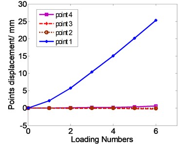
The experimental results demonstrate that the vertical displacements of single EMS modules are not interacting with each other in a certain range. The decoupling capacity of the levitation chassis is excellent. The experiment results indicate that the stable suspension of the maglev vehicle can be realized by the independent single EMS module control.
3. Dynamics model for single EMS module
Since the experiment results above demonstrate that the maglev vehicle suspension control can be simplified into single EMS Module suspension control, a single module of the electromagnetic suspension (EMS) system is shown in Fig. 9. The parameters of the magnetic suspension system in Fig. 9 are presented in Table 2.
Fig. 9Configuration of the EMS module systems
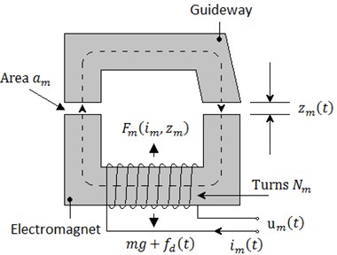
Table 2Parameters of the system
Symbol | Physical meaning |
m | Gross mass |
Fm | Magnetic force |
am | pole area of coil |
zm | Magnet displacement |
fd | Unknown disturbance |
im | current of the coil |
By Newton’s law and Kirchhoff’s law, the dynamics of the magnetic suspension system can be described by:
where, zm(t), ˙zm(t) and ¨zm(t) denote the maglev vehicle position (i.e., airgap), velocity, and acceleration, respectively, m denotes the maglev vehicle mass, g represents the gravitational acceleration constant, Fm(im,zm) represents the control force input, fd(t) denotes the vertical nonlinear, periodic and bounded disturbance force.
The uncertain nonlinear function fd(t)∈R1 is a periodical bounded function whose frequency is ω and satisfies the following equation:
In Eq. (2), Fm(im,zm) is control input. Since μ0N2mam is positive constant, Fm(im,zm) is greater than or equal to zero, which means magnetic suspension system is unidirectional control input system. Fm can be changed by regulating current im, while current im is regulating by voltage um, which can be denoted by: Rim+L˙im=um. R and L denote resistance and inductance of the electromagnet. Once the control force Fm is designed to levitate the electromagnet stably at a fixed gap, the im and um can be obtained by back-stepping approach easily. So, Fm(t) is assumed to be control input, which can be utilized to regulate the suspension height.
4. PD controller design
By Taylor expanding the nonlinear model in the equilibrium point (zref,iref), the approximate linear model can be got as follows:
where:
Pi=μ0N2mamiref2z2ref,Px=μ0N2mami2ref2z3ref,Lref=μ0N2mam2zref.
Based on the linear model, we design the following PD controller:
where, τ and Kp∈R+ are positive constant control gains.
The control schematic diagram of the system can be seen in Fig. 10. GP(s) is the transfer function of the PD controller.
Fig. 10The control schematic diagram of the system

The transfer function of the PD controller can be obtained as follows [16]:
We can obtain the open-loop transfer function of system with PD controller as:
Set the value of τ to 0.1. Through simulation calculation, the root locus of the closed-loop system and the relationship between real part of the eigenvalues and Kp are shown in Fig. 11 and Fig. 12.
Fig. 11The root locus
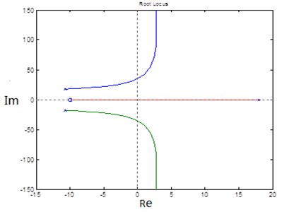
Fig. 12Real part of the eigenvalues changed by Kp
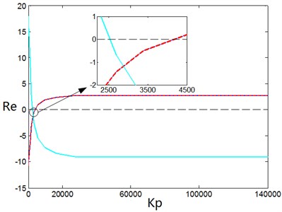
The control gains of the PD controller are chosen as: τ=0.1, Kp=4000.
The initial deviation of the electromagnet from the equilibrium point is set to 8 mm. The simulation time is set to 5 s. The simulation results of the acceleration responses of the electromagnet, the error of the airgap and phase locus of the error are shown in Figs. 13-15, respectively.
Fig. 13The acceleration responses of the electromagnet
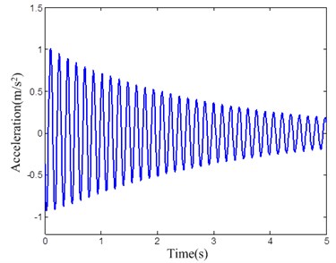
Fig. 14The error of the airgap
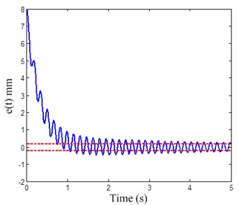
Fig. 15The phase locus of the error
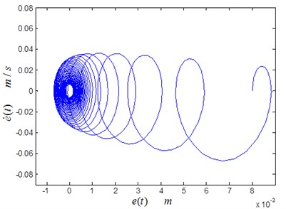
Fig. 16Periodic dynamic disturbance force
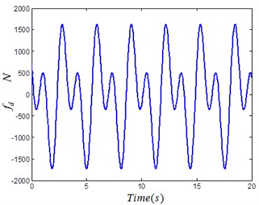
Assume that the periodic dynamic disturbance force is acted on the maglev train. The disturbance force can be defined as Fig. 16.
Apply the disturbance force into the previous control plant. The control gains stay the same and the simulation time is set to 10s. The simulation results of the acceleration responses of the electromagnet and the error of the airgap are shown in Fig. 17 and Fig. 18, respectively.
Fig. 17The acceleration responses of the electromagnet
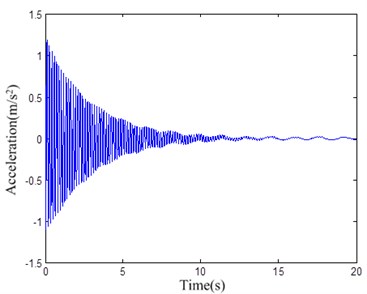
Fig. 18The error of the airgap with disturbance
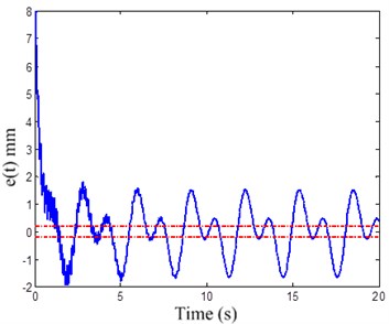
Based on the results illustrated in Figs. 13-18, it is clear that the conventional PD controller can regulate the system to be stabilized within a certain range, but the disturbance cannot be eliminated. The error of the airgap is about ±2 mm, which cannot meet the control quality request.
5. Nonlinear Disturbance Rejection Controller Design
The control objective is to specify a control force input signal which will regulate the maglev vehicle position to a desired set point in the presence of an unknown, bounded periodic disturbance force. The controller design is complicated by the lack of knowledge of the structure of the nonlinear, periodic bounded disturbance and also due to the fact that the electromagnetic suspension (EMS) systems can only implement an attraction force on the maglev vehicle. The tracking error e(t)∈Rn is defined to facilitate the following design as follow:
where, zd represents the constant desired set point position of the maglev vehicle and ξ denotes a scalar, positive control gain. It is easily to prove that if r(t) converges to zero asymptotically, ˙e(t), e(t)will converge to zero asymptotically.
According to the Eqs. (2), (3) and (8), the time derivative of tracking error (8) and can be rewrite in the following manner:
The expression of the open-loop equation above can be rewritten by mathematical manipulation:
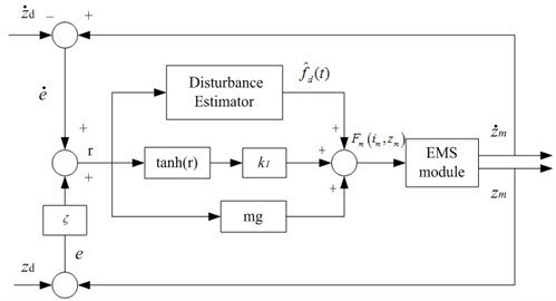
Considering the input of the controller is unidirectional, a nonlinear controller which can estimate nonlinear, periodic bounded disturbance online is designed as follows:
where, k1tanh(r) represents the nonlinear state feedback;k1 denotes the control gain; ˆfd(t) denotes the online estimation of the disturbance force fd(t) with periodic variation in the following manner:
where, the saturated function satf0(ξk) is defined as follows:
The gain of the controller must satisfy the following conditions:
Fig. 19Control block diagram of the nonlinear controller
The periodic signals are always difficult to determine in practice. So, it’s necessary to design controllers to solve the problems of a disturbance force with unknown periods. The adaptive notch filter presented in [17, 18] to estimate the unknown frequency online, then combined it with the nonlinear controller to deal with the unknown periods. The frequency of the unknown periodic signal fd(t) can be estimated online via an adaptive notch filter in following manner:
where, ˆω(t)∈R1 denotes the estimation of the frequency. ζ∈R1 denotes the damping ratio. γ∈R1 represents an adaptive gain. x(t), ˙x(t) represent the state variable of the filter. The estimation frequency ˆω(t) converges to the real frequency ω asymptotically:
Based on the method above, the frequency of the nonlinear uncertain signal fd(t) can be estimated online, and then the estimation will be applied to the nonlinear controller (11) and the estimation of the unknown disturbance force will be obtained. The control block diagram of the nonlinear controller is shown in Fig. 19.
In order to demonstrate the validity of the overall control strategy proposed in this work, the simulation of the EMS module with proposed nonlinear controller was implemented based on MATLAB [19-21].
The desired position trajectory was selected as follow:
The gross mass, initial position and initial velocity of the EMS system are chosen as:
The control gains were tuned by trial and error method [22] until a good tracking performance was achieved. This resulted in the following set of gains:
The following gains for the frequency on-line estimator were selected as follows:
And the initial frequency for the on-line estimation is selected as:
The nonlinear periodic disturbance force fd(t) is shown in Fig. 16. fd(t) is bounded and exhibits a frequency of ω=2 (Hz).
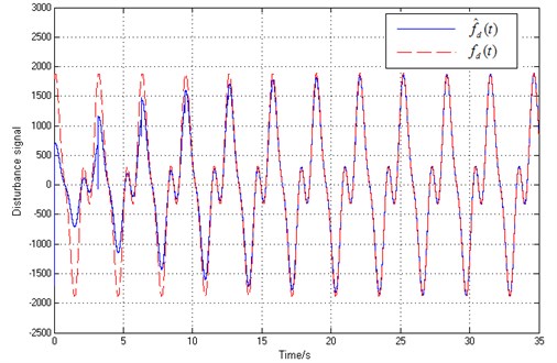
The Fig. 20 shows the maglev vehicle position tracking error e(t), while the frequency estimation signal ˆω(t) and the disturbance estimation signal of the ˆfd(t) are shown in Fig. 21 and Fig. 22, respectively.
Fig. 20Airgap error e(t) of maglev vehicle
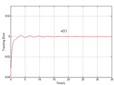
Fig. 21Frequency of disturbance force estimation
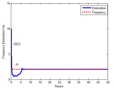
We can learn from the Fig. 16 and Fig. 18 that the error of the airgap is about ±2 mm with PD controller, but the proposed controller’s airgap error converges to zero with the same disturbance, which shows the excellent robustness. The frequency estimation ˆω(t) can converges to the real disturbance frequency within 5 s. Moreover, the disturbance estimation can estimate the real disturbance force accurately only requiring the disturbance to be bounded (the parameters, structure and period of the disturbance is not required to be known).
Fig. 22Disturbance fd(t) and disturbance estimation f^d(t)
6. Conclusions
In this paper, an experiment for the maglev vehicle is implemented to show the decoupling capacity of the levitation chassis. A dynamic model of single EMS module is constructed. A nonlinear controller for position control is proposed to reject the periodic external disturbance which ensures global asymptotic tracking desired position trajectory for the EMS module system while compensates for the unknown periodic disturbance force. Further, the controller is extended by fusing it with an on-line frequency estimator based on adaptive notch filter to remove the demand of having the period of the disturbance as a priori to carry out the controller. In addition, the EMS module system achieves maglev vehicle position regulation though the controller can only exert an attractive force onto the maglev vehicle. Simulation results are presented to validate the effectiveness of the proposed controller. Future work will focus on designing nonlinear controllers for unknown non-periodic disturbance and validating the proposed controller by experimental results.
References
-
Thornton R. D. Efficient and affordable maglev opportunities in the United States. Proceedings of the IEEE, Vol. 97, Issue 11, 2009, p. 1901-1921.
-
Lee H. W., Kim K. C., Lee J. Review of maglev train technologies. IEEE Transactions on Magnetics, Vol. 42, Issue 7, 2006, p. 1917-1925.
-
Liu S. K., An B., Liu S. K., Guo Z. J. Characteristic research of electromagnetic force for mixing suspension electromagnet used in low-speed maglev train. IET Electric Power Applications, Vol. 9, Issue 3, 2015, p. 223-228.
-
Sun Y. G., Qiang H. Y., Lin G. B., Ren J. D., Li W. L. Dynamic Modeling and control of nonlinear electromagnetic suspension systems. Chemical Engineering Transactions, Vol. 46, 2015, p. 1039-1044.
-
Denk J. Active magnetic bearing technology running successfully in Europe’s biggest onshore gas field. Oil Gas-European Magazine, Vol. 41, Issue 2, 2015, p. 91-92.
-
Asama J., Hamasaki Y., Oiwa T., Chiba A. Proposal and analysis of a novel single-drive bearingless motor. IEEE Transactions on Industrial Electronics, Vol. 60, Issue 1, 2013, p. 129-138.
-
Kim K. J., Han H. S., Yang S. J. Air gap control simulation of maglev vehicles with feedback control system. International Journal of Control and Automation, Vol. 6, Issue 6, 2013, p. 401-412.
-
Mohamed A. M., Busch-Vishniac I. Imbalance compensation and automatic balancing in magnetic bearing systems using the q-parameterization theory. Proceedings of the American Control Conference, Baltimore, USA, 2002.
-
Rodrigues H., Orgeta R., Mareels I. A novel passivity-based controller for an active magnetic bearing benchmark experiment. Proceedings of the American Control Conference., Chicago, USA, 2001.
-
Behal A., Costic B., Dawson D., Fang Y. Nonlinear control of magnetic bearing in the presence of sinusoidal disturbance. Proceedings of the American Control Conference, Arlington, USA, 2001.
-
Xian B., Jalili N., Dawson D., Fang Y. Adaptive rejection of sinusoidal disturbances with unknown amplitudes and frequencies in linear SISO uncertain systems. Proceedings of the American Control Conference, Anchorage, USA, 2002.
-
Wang H., Zhong X. B., Shen G. Analysis and experimental study on the MAGLEV vehicle-guideway interaction based on the full-state feedback theory. Journal of Vibration and Control, Vol. 21, Issue 2, 2015, p. 408-416.
-
Su X. J., Yang X. Z., Shi P., Wu L. G. Fuzzy control of nonlinear electromagnetic suspension systems. Mechatronics, Vol. 24, Issue 4, 2014, p. 328-335.
-
Ghosh A., Krishnan T. R., Tejaswy P., Mandal A., Pradhan, J. K., Ranasingh S. Design and implementation of a 2-DOF PID compensation for magnetic levitation systems. ISA Transactions, Vol. 53, Issue 4, 2014, p. 1216-1222.
-
Sun Y. G., Li W. L., Qiang H. Y., Chang D. F. An Experimental study on the vibration of the low-speed maglev train moving on the guideway with sag vertical curves. International Journal of Control and Automation, Vol. 9, Issue 4, 2016, p. 279-288.
-
Sun Y. G., Li W. L., Dong D. S., Mei X., Qiang H. Y. Dynamics analysis and active control of a floating crane. Technical Gazette, Vol. 22, Issue 6, 2015, p. 1383-1391.
-
Mojiri M., Bakhshai A. R. An adaptive notch filter for frequency estimation of a periodic signal. IEEE Transactions on Automatic Control, Vol. 49, Issue 2, 2004, p. 314-318.
-
Mojiri M., Bakhshai A. R. Stability analysis of periodic orbit of an adaptive notch filter for frequency estimation of a periodic signal. Automatica, Vol. 43, Issue 3, 2007, p. 450-455.
-
Ruan J. H., Shi Y. Monitoring and assessing fruit freshness in IOT-based e-commerce delivery using scenario analysis and interval number approaches. Information Sciences, Vol. 373, Issue 10, 2016, p. 557-570.
-
Wei W., Fan X., Song H., et al. Imperfect information dynamic Stackelberg game based resource allocation using hidden Markov for cloud computing. IEEE Transactions on Services Computing, 2016, (in Press).
-
Li J. Q., He S. Q., Ming Z. An intelligent wireless sensor networks system with multiple servers communication. International Journal of Distributed Sensor Networks, Vol. 7, 2015, p. 1-9.
-
Ruan J. H., Wang X. P. Optimizing the intermodal transportation of emergency medical supplies using balanced fuzzy clustering. International Journal of Production Research, Vol. 54, Issue 14, 2016, p. 4368-4386.
Cited by
About this article
This research is supported by Key Projects in the National Science and Technology Pillar Program of China (2013BAG19B00-01) and the National Natural Science Foundation of China (No. 51505277).

