Abstract
Chip segmentation is one of the major factors of process quality assurance while deep hole drilling. The reliable chip segmentation can be obtained if a special self-vibratory drilling head is applied. The required self-excited vibrations are maintained due to the regenerative cutting mechanism and the embedded special elastic element which provides sufficient axial flexibility. The algorithm of adaptive control with vibration velocity feedback is proposed for a self-excited vibrations maintenance. The feedback gain is adjusted by cutting continuity index in order to provide the required cutting conditions. The mathematical model of vibratory drilling process dynamics with control is presented in the paper. The results of a multi-variant simulation are also presented and analyzed.
1. Introduction
While metal drilling, continuous chip may obstruct chip removal, resulting in temperature rise in cutting area, hole surface scratch, jamming and tool breakage. Usage of vibro-drilling technology, especially for deep hole drilling, allows to provide reliable chip segmentation and removal if correct cutting conditions are used [1]. Other positive result of vibro-drilling is considerably improved quality of holes surface while machining of composite materials [2].
Vibration technology of cutting is one of the possible solutions for segmental chips obtaining. The technology feature consists of vibratory motion of tool cutting edges (or a machined workpiece) accompanying main motion of tool or workpiece rotation and feed motion while machining.
Periodical exit of tool cutting edges out of material in cutting zone and chip segmentation are possible under certain conditions [1]. As a general rule, vibration amplitude should be of an order of tool feed per tooth. The ratio of vibration frequency to rotation rate determines the amount of chip segments, formed per one revolution. But, high amplitudes and high oscillation frequency are inadmissible to avoid excessive tool wear and fatigue damage accumulation. Thus, the vibration amplitude should not considerably exceed minimal value assuring chip segmentation. In [1] it was shown that minimal amplitude of harmonic vibration, required for chip segmentation is achieved when tool oscillation amplitude is equal to a half of tool feed per tooth. Chip segmentation conditions at harmonic axial vibration for drilling could be described mathematically as follows:
where A is peak-to-peak displacement, m; a – tool feed per tooth, m/cutting edge; i – fractional portion of oscillation count, done by an instrument during one cutting edge turn.
There are two ways to excite tool axial vibration while drilling: external excitation and self-excited vibration mode. The kinematic [3] and the hydraulic [1, 4] types of exciter are commonly used for tool external excitation. In addition, vibro-drilling devices with piezoelectric [5], electro-magnetic [6] and other physical excitation mechanism are applied to provide a mechanical system with additional energy of axial oscillatory motion.
Self-excited vibrations while drilling are the subject of the present work. Vibrations arise due to the regeneration mechanism of energy supply while cutting [7]. Gist of the effect is in the act of a drill cutting edge machining a surface pre-formed by preceding passes of the cutting edges. Thus, surface irregularities, caused by previous system axial vibration affect the uncut chip thickness and cutting force at that very moment, which causes time delay in dynamic system. In that case, depending on combination of the process parameters, cutting forces can produce positive or negative mechanical work during tool axial motion causing self-excitation or damping of axial vibrations respectively.
Fig. 1 illustrates drilling process schematic drawing when vibratory holder is used. Vibratory head provides transfer of the main cutting moment and should possess sufficient lateral stiffness to exclude undesirable lateral vibrations during machining. The system axial flexibility, which is required for tool self-vibration, is ensured by a special elastic element. Mathematic modeling of a tool axial vibration for specified cutting conditions (speed rate, tool feed), material properties and tool geometry is required for the adequate choice of a vibratory head design parameters (stiffness of an elastic element, mass of a moving part) [8-12]. Special attention should be paid to the cutting forces modeling [13-15]. Paper [16] is devoted to investigation of vibro-drilling dynamics, taking into account of system torsional flexibility. Gagnol at al. [17, 18] investigated the drilling process stability without control using finite element (FE) technique for tool, vibratory head and spindle modeling. Review of the current state of self-vibration modeling while drilling is presented in [19].
The impossibility of chip segmentation control during machining process is shortcoming of such auto-vibration systems. The specific combination of vibratory head structural parameters can ensure reliable chip segmentation only under the certain cutting conditions for a given set of workpiece material properties and tool geometry. One shall take into account tool wear while machining, causing variation in its cutting characteristics. Consequently, the energy, supplied into a self-vibratory system, and vibration amplitude will change also. Moreover, in a number of practical cases the vibratory drilling with self-vibrations cannot be implemented due to the technological restrictions (e.g. limitation of machine-tool spindle speed).
Fig. 1Scheme of a self-vibratory drilling head design

It is reasonable to supplement the process based on the self-vibration mechanism by low-energy external excitation, generated, for example, by piezo actuator, built into vibratory head design [20]. The value of driving voltage supplied to actuator is determined in a feedback circuit, basing on the online measured value of the cutting force, or the acceleration of the vibratory holder moving part. Gouskov et al. [21, 22] have analyzed examples of vibratory drilling dynamics under low-energy harmonic external excitation, but without feedback control. The strategy of control by cutting continuity index was proposed in the research [23]. But the efficiency of such control for a broad range of cutting conditions was not justified.
The results of the investigation of the closed loop system model “auto-vibration vibratory head – cutting process – control system”, and the algorithm of the control, assuring chip segmentation within the specified range of material and machining parameters, are presented in this paper. The low-energy excitation is provided by a piezo actuator, flexibility of which is negligible when compared to the flexibility of the other elements of the system, and is omitted in considerations. The action of the piezo actuator is considered as the supplementary kinematic excitation. Numerical model and basic equations for the model simulation are described in Section 2. Section 3 describes the main vibratory drilling process integral characteristics, which are used later for generalization of modeling results. Section 4 contains data about the control strategy elaboration. The results of vibratory drilling multi-variant simulation taking into account control process are presented in Section 5. Section 6 lists conclusions and summary.
2. Model description
Fig. 2 shows schematic model of a drilling tool with vibratory head. Assumed, that kinematic excitation x0(t) is transferred to a vibratory head moving part by an elastic element. Moving part of a vibratory head and tool (drill) can vibrate in axial direction only, x(t) – axial coordinate of tool motion. Since a drill is considered as absolutely stiff, it is sufficient to use axial coordinate of any point of the cutting edge to define its relative distance to the machined surface. Therefore let us denote the coordinate of the point on a machined surface profile shown in Fig. 2 as s(t). The surface was generated at the last passage of the tool cutting edges in the position it occupied at the time moment t. Also feed per tooth is designated as a. At initial set t∈[-T;0] assume that x(t)=0, x0(t)=0, s(t)=at/T, where T – is the period of the cutting edges passes, associated to the tool rotation angular velocity Ω as follows T=2π/zΩ (z – number of cutting edges). The elastic element shown in Fig. 2 is non-deformed at the initial time set. The tool is immersed into the machined hole at the minimal depth, required for the full immersion of cutting edges (the hole bottom is preliminary-formed).
Fig. 2The tool model with flexible fastening
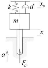
a) General model
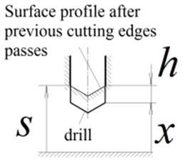
b) Cutting zone
Differential equations of the tool axially motion:
where x – is a tool axial coordinate, taken from the spring non-deformed position, m; m – mass of the moving part of a vibratory head, kg; k – stiffness of the elastic element, N/m; d – generalized coefficient of energy dissipation of moving system, N∙s/m; Fc – axial component of the cutting force, N.
The uncut chip thickness at each point of the drill cutting edges is uniform and equal to:
where H() is the Heaviside function.
Surface profile after the last cutting pass at the moment t, depends on the surface profile at the moment t-T as follows:
Hereinafter, the cutting law is presumed as an exponent function [8]:
where Kc and r – are the empirical coefficients, depending on the cutting part geometry and machined material.
Let us reduce Eqs. (2)-(5) to dimensionless form by presentation of all displacements and geometrical parameters as a ratio to feed per tooth a:
where q is the dimensionless displacement, Λ – dimensionless surface coordinate, η – dimensionless cutting depth.
Let us introduce dimensionless time τ=t/T and dimensionless cutting force Pc=Fc/ka. As the result the dimensionless set of the equations is reduced to:
with the following designations: p=√k/m/zΩ – is the ratio of the eigenfrequency of a vibratory head axial vibrations to the tooth pass frequency, ζ=d/2√km – dimensionless damping coefficient, kc=Kc/ka1-r – dimensionless cutting coefficient.
Thus obtained set of Eqs. (6)-(9) is a nonlinear one with delayed argument in the Eqs. (7), (9). In the present paper the unknown variables {q, η, Pc, Λ} are numerically determined on discrete mesh with uniform step Δτ:τj=jΔτ, j=0, 1, 2,…. At each jth time step τ∈(τj,τj+1] method of successive approximations [24] with iterative improvement of the state vector at the end of a step was applied. Algorithm of the applied method is described in Appendix. Convergence criteria of an iteration cycle was taken as:
where x={q,˙q}T is the system state vector, n – number of iteration, ε – acceptable error, herein is 0.001.
3. Integral characteristics of vibratory drilling process
The main variables which describe the tool dynamic behavior while drilling are the time-dependence of a drill axial displacement and the cutting force. In addition to those functions, the spectrum of tool displacement and cutting forces are also indicative. But to investigate the effects of machining parameters (herein – p, kc) on a system vibrations, it is necessary to introduce characteristics of the oscillating process cumulatively. As estimation, the following characteristics are proposed: the peak-to-peak displacement, the maximum cutting force and the cutting continuity index determined at a steady-state section of the process.
Peak-to-peak displacement is defined as the difference between the biggest and the smallest tool displacement on a certain preselected interval at the end of the modeling time:
where τf – final moment of the modeling time, ΤA – dimensionless time interval under consideration. When analyzing modeling results, it was assumed that ΤA=100.
Similarly, the maximum cutting force on a steady-state section of the process is defined as:
Cutting continuity index is determined as a ratio of time when drill edges are immersed into material to the complete time interval under consideration:
Dependence of the listed characteristics on the variable parameters p and kc is presented in the form of contour chart on which iso-line of a parameter under consideration is presented in-plane of 2 parameters data. To improve visualization, the areas between iso-lines are drawn in different colors.
4. Elaboration of vibro-drilling process control
4.1. Summary of piezo actuator application
Piezo actuator which transforms electrical voltage into deformation [25] is used for the tool controlled excitation. Fig. 3 shows multilayer piezoelectric actuator scheme consisting of ceramic laminates. Within operational range of voltage, the piezo actuator reaction versus controlled voltage is linear. Maximum displacement in the multilayer actuator is described as follows:
where d33 is the material piezoelectric modulus, coulomb/N; n – number of layers in piezo actuator; U – voltage, V.
Fig. 3Multilayer piezoelectric actuator
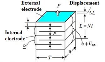
Preliminary calculations proved that piezo element is capable of deforming up to 20-40 µm, which is approximately 0.1-0.2 of a tool feed per tooth. For dynamics modeling, described in Section 2, q0 absolute magnitude is limited by value 0.1 of the tool feed.
4.2. Measuring tools
Special measuring system is required to control system correct work, capable of measuring such parameters as the vibration velocity and the cutting force.
For vibration velocity measurement can be implemented by indirect method. Piezoelectric accelerometer with build-in electronics, mounted on the moving part of a vibratory head, is reasonable to be used. The analogue signal from the accelerometer is transformed into digital signal of vibration velocity by analog to digital converter (ADC) with a charge balance. Such type of ADC allows to clear automatically the signal from noise and higher harmonics, and to integrate the acceleration signal at high speed processing about 4000 counts per second [26].
The cutting forces are measured by means of a piezo element placed between the multilayer piezoelectric actuator and the auto-vibration system. It is noteworthy that signal amplifier is required to ensure correct work of a piezo element as a force-gauge. Interrelation between force acting on a piezo element and the imposed voltage is described by the following relations:
where A – cross-section, m2; E – piezo material modulus of elasticity, Pa; L – length of piezo element, m.
The signal generated by piezo element is proportional to the sum of the cutting force and the inertial forces acting on the moving part of a vibratory head. To extract the cutting force value from the received signal, the member responsible for the inertial forces (product of the vibratory head moving part mass and the acceleration) should be subtracted from the sum. Calculation of the cutting continuity index ψ in this paper is carried out by Eq. (11), periodically with the dimensionless time interval ΤA=2 (which for 2-fluted drill corresponds to the rotation period).
4.3. Control strategy
Ensuring of the required value of the cutting continuity index ψ0 is an objective of control Since excessively high vibration amplitudes are undesirable, the range recommended value of ψ0 is (0.8; 1.0). It should be noted that ψ=1 means the continuous cutting.
It is assumed that the control law is proportional to the vibratory head moving part axial velocity:
where b – is the velocity feedback gain and is an adaptable value. Positive value of b corresponds to the system energy supply, and the negative value means the energy dissipation.
Variation of b is described by the formula:
where c – is the adaptation parameter. Factor b correction is carried out after each step of cutting continuity index ψ computation.
Thus, if vibration amplitude in a cutting zone is insufficient for assuring the target cutting continuity index, factor b is increased and additional energy is supplied into the system. As the result, the vibration amplitude is increasing and the cutting continuity index is decreasing. If vibration amplitude is excessive and ψ<ψ0, then the factor b is decreasing, and thus restricting vibration amplitude.
5. Results of modeling
The paper presents the results of the multi-variant modeling of system dynamics, described in Section 2, taking into account the control algorithm, described in Section 4.3. The integral process characteristics described in Section 3 are calculated for a set of parameters p and kc. This section describes summary of obtained results. The following parameter values were used for the simulation: ζ=0.01, r=0.75, c= 0.002, ψ0= 0.9. The integration step was taken as: Δτ=τj+1–τj= 0.01. The integration time was taken as 500 which correspond to 500 delay periods. Fig. 4 presents maps of the displacement peak-to-peak values, the maximum cutting force and the cutting continuity index. The dimensionless parameter p is depicted along abscissa axis and the dimensionless parameter kc – along ordinates axis. The two cases were considered: without control and with control including adaptation of the feedback factor b.
The results presented in Fig. 4 show the periodically repeated dependence of dynamic process characteristics on the parameter p. The system behavior on the interval 1<p<2 is quite similar to the behavior on the interval 2<p<3 and other similar intervals. That is why for example we consider only the interval 1<p<2 for the following discussions.
Darker areas in Fig. 4 present the set of parameters corresponding to vibrations with smaller amplitudes, and the lighter shades – bigger amplitudes. The only exception from that rule is used for the maps of cutting continuity index ψ: on those maps the white areas present areas of parameters where chips segmentation is absent. It should be noted that at values of 1<p<1.5 in case of control absence, there is a dark area without chips segmentation tapering upwards. In the range of 1.5<p<2 chips segmentation presents practically everywhere, except for very small values of kc.
Fig. 4Maps of the steady-state parameters of the oscillating cutting process. Left-hand side а), b), c) – without control, right-hand side d), e), f) – with control. а), d) – maps of cutting continuity index; b), e) – maps of steady-state peak-to-peak displacement; c), f) – maps of the maximum values of the steady-state cutting force
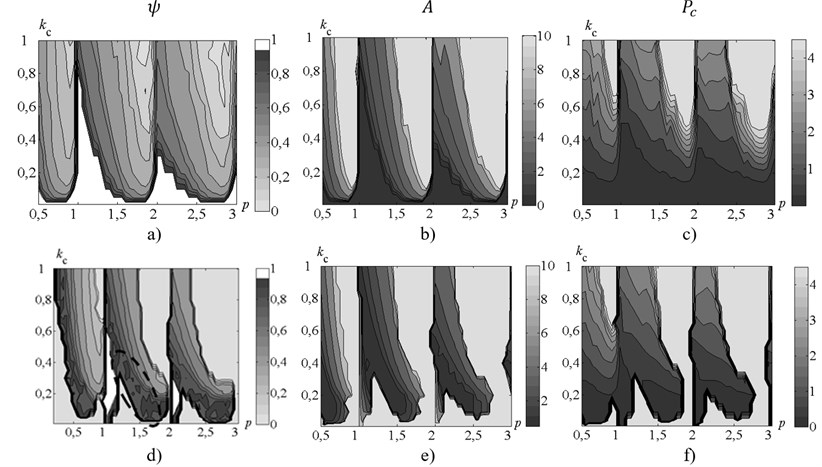
It is seen from Fig. 4(а) that the area presenting the desired range of cutting continuity index ψ∈(0.8; 1.0) is very thin. It should be noted that the cutting coefficient kc, unlike the parameter p (associated with rotation rate), as a rule, is specified with insufficient accuracy. That is why it does not seem to be possible to ensure chip segmentation with the desired value of cutting continuity index ψ without feedback. The results presented in Fig. 4(d) show, that under process control, area presenting the desired value of cutting continuity index ψ (contoured by dashed line) significantly increased and became about 0.2 wide along kc axis. Thus the control algorithm presented in this paper allows to provide chip segmentation under the conditions of considerable uncertainty (about 30 % of the desired value) of cutting coefficients values.
Fig. 5Allocation of points, for which time histories are presented. Points are on the map of cutting continuity index without control. Solid black thick lines represent the stability borders of the linearized system.
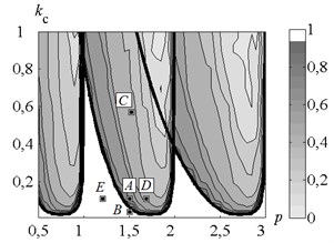
Let us consider the dynamic process time history in more detail for different values of the machining parameters. The main attention during this analysis will be paid to the region where the cutting coefficient values (i.e. cutting forces) are near the minimal required level (Fig. 5) to provide the self-excited behavior of the dynamic system. Four points (A (p=1.5; kc=0.1), B (p=1.5; kc=0.02), D (p=1.7; kc=0.1), E (p=1.2; kc=0.1)) were chosen for the detailed analysis in this region on the machining parameters plane (Fig. 5) near the linearized self-excited system stability border (solid black thick lines in the Fig. 5) which corresponds to the border between ψ=1.0 and ψ<1.0 areas. It is possible to expect the minimal required values of the actuator additional excitation to the system to provide reliable chip segmentation when operating near the stability border. The additional point C (p=1.5; kc=0.6) in the area with high values of the cutting forces coefficient and too low values of ψ was also selected for the comparative analysis. For each of those points variations in time of process variables have been analyzed. Two cases were considered: with control and without control.
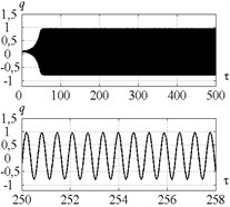
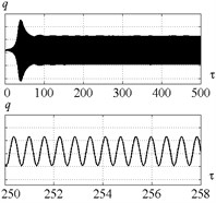
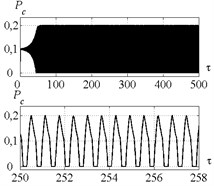
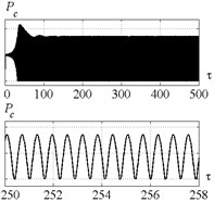
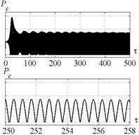
Time histories of the tool displacements and cutting forces for points A, B, C, D, E, are presented in Figs. 6, 7, 9, 11, 12 respectively. Fig. 6 indicates, that introduction of control in point A (Fig. 5) limits the system vibration insignificantly. The cutting continuity index ψ reaches the level of about 0.9. In case without control ψ≈0.7; the value indicates excessively high vibration amplitudes. The system demonstrates dynamic behavior, qualitatively similar to the behavior at point A, in all points, adjacent to the stability border (Fig. 5). The developed control algorithm demonstrates full efficiency and allows to limit peak-to-peak displacement and to provide the desired value of ψ when operating in the region with chip segmentation and excessively high amplitudes.
Fig. 6Time history of tool displacement (diagrams a), b)) and cutting forces (diagrams c), d)) in case of no-control a), c) and with control b), d). The values of the parameters p and kc correspond to A point
a)
b)
c)
d)
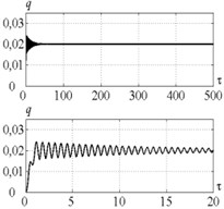
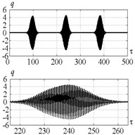
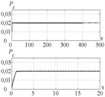
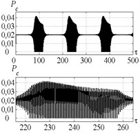
Fig. 7Time history of tool displacement (diagrams a), b)) and cutting forces (diagrams c), d)) in case of no-control a), c) and with control b), d). The values of the parameters p and kc correspond to B point
a)
b)
c)
d)
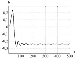
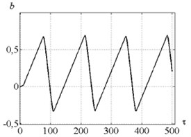
Fig. 8Time history of b – velocity feedback gain: a) for parameters combination of the point A, b) for point B
a)
b)
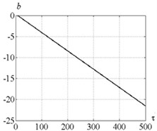
Fig. 7 indicates that in case of no-control in point B (Fig. 5) the tool vibration decreases and no chip segmentation takes place (see Fig. 7(d) where the cutting force has positive values only). Introduction of control does not make the desired steady-state process. To investigate the reason of such effect, let us consider Fig. 8 presenting dependence of the feedback gain for points A and B (Fig. 5). It indicates that at the point A the feedback coefficient has positive value at the beginning and facilitates system vibration excitation, but then it comes down below zero and thus limits the system vibrations. At the point B the feedback coefficient first gradually increases. It is required for amplitude raising and starting of chip segmentation. Then coefficient runs up to certain critical value and vibration amplitude becomes excessively high. After that feedback coefficient starts decreasing until chip segmentation has been stopped. Thus, at small values of kc the control algorithm demonstrates unstable behavior. And that is the major disadvantage of the strategy proposed in this paper.
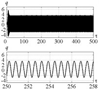
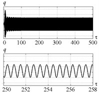
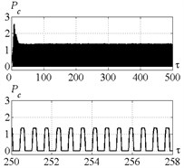
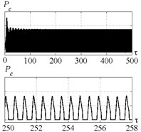
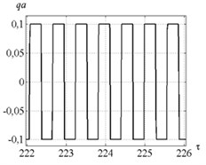
Fig. 9 indicates that introduction of control for point C (Fig. 5) limits the vibration amplitude insignificantly. The index ψ is approximately equal to 0.45. Such considerable deviation of the index from the required value is caused by the restriction imposed on the actuator’s vibration amplitudes qa (Fig. 10).
Fig. 9Time history of tool displacement (diagrams a), b)) and cutting forces (diagrams c), d)) in case of no-control a), c) and with control b), d). The values of the parameters p and kc correspond to C point
a)
b)
c)
d)
Fig. 10a) Time history of actuator elongation and b) feedback factor for parameters combination of the point C
a)
b)
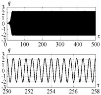
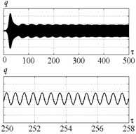
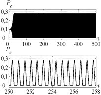
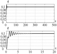
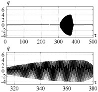
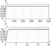
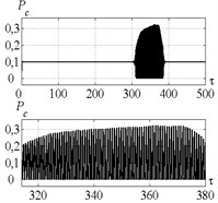
It is seen from Fig. 11 that in case of the control corresponding to the point D (Fig. 5) the actuator insignificantly restricts the vibration amplitude down to the desired value of cutting continuity index. The system dynamic behavior in this case is similar to the point A. Fig. 12 indicates that the control at point E (Fig. 5) leads to the same system vibrations destabilization similarly as for point B.
Fig. 11Time history of tool displacement (diagrams a), b)) and cutting forces (diagrams c), d)) in case of no-control a), c) and with control b), d). The values of the parameters p and kc correspond to D point
a)
b)
c)
d)
Fig. 12Time history of tool displacement (diagrams a), b)) and cutting forces (diagrams c), d)) in case of no-control a), c) and with control b), d). The values of the parameters p and kc correspond to E point
a)
b)
c)
d)
6. Conclusion
The mathematical model of a vibratory drilling process dynamics with control proportional to vibration velocity is presented in the paper. The algorithm of feedback gain adaptation with the control of cutting continuity index was elaborated. System dynamic behavior is investigated under different combination of system parameters without and with control.
It was shown by means of numerical simulation for the set of parameters combinations, that the proposed control algorithm limits vibration amplitudes down to the limit corresponding to the desirable value of cutting continuity index for a wide range of rotation rate and cutting parameters combinations. Consequently, the proposed strategy of the process control by axial vibration velocity allows to insure the required conditions in the cutting zone even in case of considerable scatter of cutting coefficient values. The obtained results prove that scatter of the cutting coefficient values up to 30 % will not disturb the desirable cutting conditions with chip segmentation due to proposed control strategy.
But when a vibration system requires energy supply, the proposed algorithm demonstrates unstable behavior. Such instability is due to the lack of vibration process control at the stage of vibration growth when a chip isn’t segmented yet. So, it is advisable in the subsequent works to investigate the system control by peak-to-peak vibration displacement.
Another factor lessening range of effective implementation of the proposed algorithm is the limitation of the actuator's vibration amplitudes. This restraint causes impossibility of essential vibration limitation in the regions where the system vibrations amplitudes are very high without control.
References
-
Poduraev V. N. Cutting with Vibrations. Machinostroenie, Moscow, 1970, (in Russian).
-
Arui S., Vijayaraghavan L., Malhotra S. K., Krishnamurthy R. The effect of vibratory drilling on hole quality in polymeric composites. International Journal of Machine Tools and Manufacture, Vol. 46, Issues 3-4, 2006, p. 252-259.
-
Jallageas J., Knevez J. Y., Cherif M., Cahuc O. Modeling and optimization of vibration-assisted drilling on positive feed drilling unit. International Journal of Advanced Manufacturing Technology, Vol. 67, 2013, p. 1205-1216.
-
Popov V. E., Vainshenker E. A., Margulis M. M. Electro-Hydraulic Drive of Vibratory Drilling Machine with Programmed Control. Patent USSR, No. 510351, 1976, (in Russian).
-
Benevolskiy V. F., Makarov B. G., Silin N. S., Utkin N. F. Tool for Vibratory Processing of Deep Holes. Patent USSR, No. 1253745, 1985, (in Russian).
-
Starov V. N., Maslennikov A. V., Barbotko A. I. Method of Vibratory Drilling with the Fine Chip Segmentation. Patent RF, No. 2412023, 2008, (in Russian).
-
Altintas Y. Manufacturing Automation. Second Edition. Cambridge University Press, New York, 2012.
-
Batzer S. A., Gouskov A. M., Voronov S. A. Modeling vibratory drilling dynamics. Journal of Vibration and Acoustics, Vol. 123, 2001, p. 435-443.
-
Tichkiewitch S., Moraru G., Brun-Picard D., Gouskov A. Self-excited vibration drilling models and experiments. CIRP Annals – Manufacturing Technology, Vol. 51, Issue 1, 2002, p. 311-314.
-
Paris H., Tichkiewitch S., Peigne G. Modelling the vibratory drilling process to foresee cutting parameters. CIRP Annals – Manufacturing Technology, Vol. 54, Issue 1, 2005, p. 367-370.
-
Moraru G. Nonlinear dynamics in drilling and boring operations assisted by low frequency vibration. Proceedings of ASME 2007 International Design Engineering Technical Conferences and Computers and Information in Engineering Conference, 6th International Conference on Multibody Systems, Nonlinear Dynamics, and Control, Vol. 5, 2007, p. 951-960.
-
Moraru G. System Behavior Study “Part-Tool-Machine” in Vibration Cutting Regime. Engineering Sciences (Physics), Arts et Métiers ParisTech, 2002, (in French).
-
Guibert N., Paris H., Rech J. A numerical simulator to predict the dynamical behavior of the self-vibratory drilling head. International Journal of Machine Tools and Manufacture, Vol. 48, 2008, p. 644-655.
-
Paris H., Brissaud D., Gouskov A., Guibert N., Rech J. Influence of the ploughing effect on the dynamic behaviour of the self-vibratory drilling head. CIRP Annals – Manufacturing Technology, Vol. 57, 2008, p. 385-388.
-
Guibert N., Paris H., Rech J., Claudin C. Identification of thrust force models for vibratory drilling. International Journal of Machine Tools and Manufacture, Vol. 49, 2009, p. 730-738.
-
Voronov S. A., Gouskov A. M., Kvashnin A. S., Butcher E. A., Sinha S. C. Influence of torsional motion on the axial vibrations of a drilling tool. Journal of Computational and Nonlinear Dynamics, Vol. 2, Issue 1, 2006, p. 58-64.
-
Forestier F., Gagnol V., Ray P., Paris H. Model-based cutting prediction for a self-vibratory drilling head-spindle system. International Journal of Machine Tools and Manufacture, Vol. 52, 2012, p. 59-68.
-
Mousavi S., Gagnol V., Ray P. Machining prediction of spindle-self-vibratory drilling head. Journal of Materials Processing Technology, Vol. 213, 2013, p. 2119-2125.
-
Voronov S. A., Guskov A. M., Ivanov I. I., Barysheva D. V., Kiselev I. A. Existing methods for ensuring low frequency tool vibrations to chip breakage in deep drilling. Science and Education of the Bauman MSTU, Vol. 12, 2014, p. 842-857, (in Russian).
-
Moraru G., Veron P., Rabate P. Drilling Head with Axial Vibrations. Patent U.S., No. 20120107062 A1, 2012.
-
Gouskov A. M., Voronov S. A. Dynamic models generalization of manufacturing systems with single-point cutting. Considering equations of new surface formation. Proceedings of the 2nd Workshop Organized by Working Group 2 “Nonlinear Dynamics and Control”, Budapest, 2001, p. 7-17.
-
Gouskov A. M., Voronov S. A., Batzer S. A. Chatter synchronization in vibratory drilling. Dynamics, Acoustics and Simulations/ASME, Vol. 68, 2000, p. 263-270.
-
Gouskov A. M. Elaboration of Methods for Development and Analysis of Machining Dynamic Models. Doctoral Dissertation, Bauman MSTU, Moscow, 1997, (in Russian).
-
Demidovich B. P., Maron I. A., Shuvalova E. Z. Numerical Methods of Analysis. Functions Approximation, Differential and Integral Equations. Nauka, Moscow, 1967, (in Russian).
-
Tichy J., Erhart J., Kittinger E., Privratska J. Fundamentals of Piezoelectric Sensorics: Mechanical, Dielectric, and Thermodynamical Properties of Piezoelectric Materials. Springer, 2010.
-
McCreary J., Gray P. All-MOS charge redistribution analog-to-digital conversion techniques. Part 1. IEEE Journal of Solid-State Circuits, Vol. SC-10, Issue 6, 1975, p. 371-379.
About this article
The research was funded by the financial support of Ministry of Education and Science, NIR N 9.1073.2014K under the design part of the State-guaranteed order in scientific research area.
