Abstract
Robotic drilling technology for aircraft flexible assembly has challenges and is under active investigation. In this work, a robotic drilling end-effector is designed and its normal adjustment system is dynamically modeled for comparison of advanced control strategies in terms of position tracking precision and dynamic quality. Three control algorithms with different computational complexity are proposed and compared: Based on computation torque control method first, a proportional and differential controller (PDC) and a sliding mode controller (SMC) are proposed respectively, and then is a model reference adaptive controller (MRAC). Simulation results show that the SMC has higher precision and a more excellent tracking property than the PDC of which the proportional and derivative gains have been optimally tuned using a modified Ziegler-Nichols’ (Z-N) tuning methods. An experiment platform is established in MatLab xPC environment to validate the effect of the SMC and MRAC. The experiment results show that the MRAC delivers a better robust performance that allows adaptiveness to the nonlinear factors such as disturbance and parameter variations than the SMC.

Highlights
- By using computation torque control method, a proportional and differential controller (PDC) and a sliding mode controller (SMC) were proposed respectively for robotic drilling system.
- To further improve the dynamical control quality, a model reference adaptive controller (MRAC) was developed.
- Experiment performed on the designed robotic end-effector verified that the MRAC achieves tracking within a desired precision.
1. Introduction
Aircraft structure is generally fastened by solid rivets, which requires a large number of drilling holes on a flexible surface. Therefore, the efficiency and quality of drilling has a prominent impact on airplane assembly cycle and quality. Since industrial robot has been successfully used in automotive production for several years, applying industrial robots to aero-structure production and assembly has aroused increasing interest [1]. Robotic drilling technology based on industrial robot platform has intrigued a lot of interests of both the industry and academia [2]. DeVlieg et al. [3] brought up a new concept of combining an off-the-shelf industrial robot and a multifunction end-effector for automated drilling, countersinking, and holes inspection, and built a drilling system named ONCE for the skin to substructure join on the F/A-18E/F Super Hornet wing trailing edge flaps. They further developed the second generation of the ONCE to drill holes as well as trim the trailing edge and tooling lugs from the Carbon Fiber Reinforced Plastic skins of Boeing 737 [4]. Moreover, Bi and Liang [5] proposed a robotic drilling system capable of weld mark inspection, one-sided clamping, drilling and reaming hole in material stack combinations of titanium and aluminum, and real-time thrust force feedback, for drilling in titanium structures.
The end effector plays a key role in the robotic drilling system. To ensure the perpendicular accuracy of drilling holes in aircraft assembly, it is essential to adjust the attitude of spindle axis to coincide with the normal vector of drilling point before drilling. Therefore, the performance of normal adjustment system of drilling end effector will have a significant effect on accuracy and efficiency of robotic drilling system [6]. Coupled to the ONCE robotic drilling system is a dedicated lightweight multifunction drilling end-effector controlled by a Fanuc CNC [3, 4]. Similar to ONCE, [7] proposed a robotic drilling end-effector used on industrial robots, which has detection capacity of dull, breakthrough and broken bit and can obtain the curve diagram of the real-time thrust force by using force feedback. It can also change the spindle speed according to different materials. Devlieg [8] likewise developed a multi-function robotic drilling end-effector for 737 inboard flaps drilling with the functions of providing one-sided pressure to the work piece, auto-normalization, self-lubrication, vacuum chips extraction, automated vision, automated touch probing, precision drilling and countersinking, hole inspection, and milling, which is controlled with the Siemens CNC. In order to drill in huge parts hard to move, Yuan et al. [9] put forward a bionics robotic drilling end-effector which moves along two mutually perpendicular flexible railways to realize flexible drilling. In contrast, Zhan and Wang [10] introduced a hand-eye vision system for calibration and positioning of a robotic drilling end-effector and analyzed the primary error of positioning. Alternatively, Zhu et al. [11] provided an approach of measurement and compensation of positioning error based on 2D vision system by using four laser displacement sensors to ensure perpendicularity of the camera optical axis to the workpiece surface and correct object distance in the measurement process. Researchers have proposed various methods of normal measurement and adjustment [12-14]. However, these efforts focus mostly on integrate multi-functional end-effector design [15], positioning and calibration method development and static accuracy ensuring, kinematics of the normal adjustment, and few studies have been investigated with respect to dynamic model and control of the normal adjustment. In order to tackle the dynamic disturbance effects and non-linearizing problems such as friction and system parameter variations, carrying out the research of the dynamic models and control of normal adjustment of the robotic drilling end-effector is of great worth. In this paper, a robotic drilling end-effector is first developed, the dynamics characteristics of the auto-normalization are next analyzed and three control strategies is further proposed and compared. Consequently, the control performance is demonstrated by simulations and experiments.
The paper is structured as follows. In Section 2, a robotic drilling end-effector is first introduced, and the dynamic characteristic of normal adjustment is then analyzed and the dynamic model is afterward presented. In Section 3, based on controller decomposition method which combines the linearized feedback of joint parameters with servo compensator, a PD controller and a SM controller are investigated respectively. Furthermore, an MRA controller is proposed. In Section 4, simulations about the PD controller and SM controller are conducted separately. In Section 5, an experiment platform is first established based on MatLab xPC RTW environment, and the experiments of SM controller and MRA controller on the designed end-effector using respectively step input and sinusoidal input are then carried out and the experimental results are subsequently compared. Lastly, the conclusions are presented in section 6.
2. Background
A diagram and a photograph of a developed robotic drilling end-effector are shown in Fig. 1. The main functions of the proposed robotic drilling end-effector include: Measuring and calculating the outward normal of the fuselage skin surface at drilling point, adjusting spindle axis to coincide with the normal and drilling after the skin is reliably compressed.
Fig. 1The designed robotic drilling end-effector
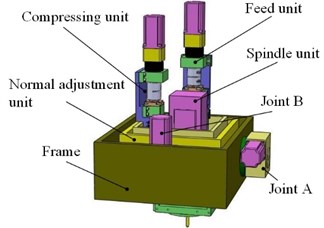
a) Illustration of the end-effector
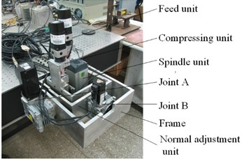
b) Prototype of the end-effector
The coordinate system of the designed robotic drilling end-effector is defined as Fig. 2. The base coordinate system is placed in the rotating joint A and is concentric exactly with joint coordinate {1}.
Fig. 2Coordination definition of the end-effector
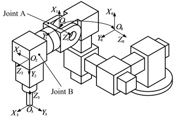
The overall rotation and translation matrices indicating terminate frame (frame {3}) of the end-effector into base (frame {0}) is given by Eq. (1):
where cθidenote cos(θi) and sθidenote sin(θi), i= 1, 2. θ1 and θ2 are the rotation angle of joint A and B, respectively.
Homogeneous Transformation matrix which represents the kinematic model of the end-effector is expressed as:
where d3 is the linear displacement of the prismatic joint of feed unit. Because the feed unit remains stationary during the normal adjustment, the effect of the d3 is ignored.
The normal adjustment is composed of joints A and B, coupled with some displace sensors. By using Lagrange equation, the dynamical equation of normal adjustment system of the designed robotic drilling end-effector is described as:
where D is the positive definite symmetric inertia matrix; H is the centrifugal and Coriolis force vector; G is the gravity vector. F(Θ,˙Θ,¨Θ) denotes friction torque vector; τd denotes disturbance torque vector. Θ=[θ1θ2]T, τ=[τ1τ2]T, τ1 and τ2 are the torques act on joint A and B, respectively.
3. Control strategies design
Utilizing controller decomposition [13], a dynamic control architecture combining the linearized feedback of joint parameters with servo compensator is adopted. The feedback linearization method which is often called computation torque control is a kind of design method based on system dynamic model. The total control quantity includes two parts: one part is the output control quantity of controller based on linearized feedback and the other part is nonlinear part and is directly computed from the model. The torque input is defined as:
with:
β=H(Θ,˙Θ)+G(Θ)+F(Θ,˙Θ,¨Θ)+τd,
where u denotes the control quantity.
Submitting Eqs. (4) and (5) into Eq. (3), it can be obtained that:
3.1. Model-based PDC
According to the approach introduced in [17], the servo control law of the PDC is defined as:
with:
Submitting Eq. (7) into Eq. (6), the error equation of the closed-loop system is deduced as:
where KP=diag(kP1,kP2) and KD=diag(kd1,kd2) are the control parameters of the PDC.
The vector equation Eq. (9) can be decoupled because that KD and KP are both symmetric positive definite matrixes. Thus Eq. (9) can be rewritten independently for each joint as:
The final input torque τ of the controller can be deduced by substituting Eqs. (5) and (7) into Eq. (4):
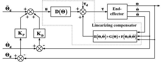
The control block diagram of the PDC based on the model with friction and gravity compensation is shown in Fig. 3, in which the frame bordered by the dashed line represents the linearizing compensator. The whole system consists of a sevo compensator and a linearizing compensator in form. We can use the method of linear system to design the controller. The output control quantity “u” of the servo compensator with the PDC acts as the input of the linearizing compensator. Consequently, the total torque “τ” input into the end-effector includes three parts expressed as Eq. (11).
3.2. Model-based SMC
On the basis of the method presented in [18, 19], a SMC with the reaching law is designed according to the dynamical model. The switch function is taken as:
where:
Using switch law can ensure the dynamic quality of the phase trajectory during reaching segment by designing the change rate function of the switch function of reaching segment [20]. This method makes the system reach the sliding surface quickly according to the dynamic characteristic of the change rate function ˙S.
Fig. 3The block diagram of PDC based on model with fiction and gravity compensation
Exponential reaching law has good dynamic characteristics that make the system reach the sliding surface quickly and eliminate system chattering effectively [21]. The exponential reaching law is expressed as:
with:
To get an insight into the stability of the proposed SMC, a Liapunov’s function is made as:
The first-order derivative of Eq. (16) is calculated as:
Substituting Eq. (12) and Eq. (13) into Eq. (15), we can obtain that:
Thus, the stability of the system with the proposed SMC is proved by using Lyapunov method.
By derivative of Eq. (12) and then substituting Eq. (6) into it, the change rate function can be obtained as:
By correlating Eqs. (13) and (16), the control quantity can be expressed as:
The final output torque τ of the controller can be deduced by substituting Eq. (17) into Eq. (4):
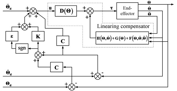
The control block diagram of the SMC based on the model with friction and gravity compensation is shown as Fig. 4. The output control quality “u” of a servo compensator with the SM controller acts as the input of the linearizing compensator. Subsequently, similar with the PDC, the total torque “τ” input into the end-effector includes three parts expressed as Eq. (16).
Fig. 4The SMC block diagram
3.3. MRAC
With the nonlinearity, time variation and strong coupling of the end-effector, the system parameters change with the joint angles, which increase the control difficulty. From the simulation of the sliding mode control, we can find that the position tracking error changes obviously with the frequency of the input sine function which implicates that the sliding mode has limitation in the dynamics control of the normal adjustment of the robotic drilling end-effector.
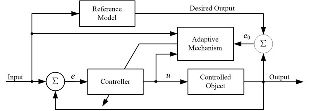
Adaptive control can modify its own performance characteristics without delay, which can adapt to not only the dynamics change of the controlled object but also the disturbance change and lead to robust performance for the overall system [22]. The MRAC is a kind of mature control system both in theoretical study and practical application [23]. The basic block diagram of MRAC is shown in Fig. 5. The design of the MRAC usually doesn’t require that the parameters of controlled object are known, but the structure and relative order of controlled object must be known [24].
Fig. 5The basic block diagram of MRAC
The reference model needs to be determined first. According to the dynamics model of the end-effector expressed by Eq. (3), then, we can confirm that the end-effector dynamics equation denotes a nonlinear second order system. And in the condition of ignoring the nonlinear factors such as friction, inertial and Coriolis force and gravity, the dynamic model is predigested into a second order linear system expressed as Eq. (19):
Hereby, we should construct a second order linear system as the reference model. And the reference model is designed to satisfy the performance requirements under the unit step input. The required indicators are presented as follows:
1) Maximum overshoot: σ % ≤ 1 %;
2) Adjusting time: ts≤ 0.01 s;
3) The steady-state output error is zero.
To attain the above desired response and to ensure the global asymptotic stability of the closed-loop, the poles of the closed-loop system can be assigned as: λ*1,2= –300 ± j200. Thus, the required reference model is described as:
Given the requirement of the reference model and the MRAC design method, M(s) must be a strictly positive real and stable minimum phase system, but the system with relative order of two doesn’t meet this condition. However, if L(s)=s+a is chosen and multiplied by M(s), N(s)=M(s)L(s) can satisfy the requirements of strictly positive realness only if the proper “a” is chosen:
To make Eq. (21) achieve the strictly positive real conditions, however, there are two prerequisites as follows:
1) N(s) is stable;
2) N(s) is positive real, that is for all ω> 0, Re[N(jω)]> 0.
By the characteristic polynomial of N(s), N(s) suffice the stability condition. Then we need to calculate the “a” that meets the positive real condition.
From Eq. (23), it can be derived that: if 0 <a< 600, then Re[N(jω)]> 0 is sufficed.
In the light of the means proposed in [25], the model reference adaptive controller is designed. The structure of the model reference adaptive controller is:
˙w(2)=Λw(2)+bλyp,
wT=[r,w(1)T,yp,w(2)T],
θT=[c0,cT,d0,dT],u=θTw
where Λ∈R(n-1)×(n-1); bλ∈Rn-1 is controllable standard form:
Identifier structure is described as the following forms:
e0=yp-ym.
Adaptive law (grade arithmetic) is expressed as:
The above controller is designed based on Lyapunov stability theory, but the proofs of the stability are complicated and prolix, [26] gives a detailed demonstration of such kind of controller.
In this system, n= 2, thus Λ=[λ1] and bλ= [1].
The parameters during the experiment is set as: a= 100, λ1= 10, g= 5.
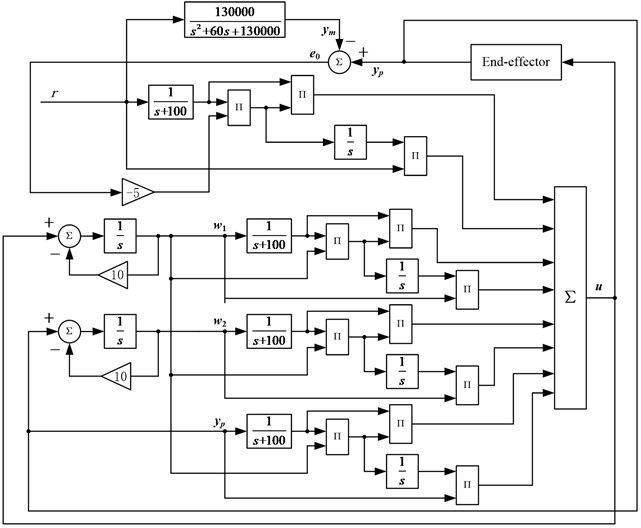
Thereby, the overall structure of the MRAC with a relative order of two, designed according to above parameters, is shown in Fig. 6.
Fig. 6The overall structure of the MRAC
4. Simulations results
4.1. Simulation preparation
In order to compensate the friction torque, it is necessary to establish a friction model to estimate the friction torque. Stribeck model is a classical friction model which describes the mechanical characteristics of various friction stages perfectly and its mathematic description is given as [27, 28]:
where ωs is Stribeck velocity; Fc denotes Coulomb friction force; Fs denotes maximum static friction force; Fv denotes viscous friction coefficient; Fe denotes the driving force; and γ is a very small positive constant.
The parameters of the Stribeck friction model of both Joints are set as Table 1 by engineering experiences.
Table 1Stribeck friction model parameters of joints A and B
Parameters | Values | Parameters | Values |
γ | 0.01 | Fc1 | 0.04 N·m |
δ | 1 | Fc2 | 0.02 N·m |
Fs1 | 0.1 N·m | Kv1 | 0.02 |
Fs2 | 0.05 N·m | Kv2 | 0.01 |
Fs1 and Fs2 are the maximum static friction force of joint A and B, respectively | |||
Given that the disturbance torques acting on the two joints are:
τd2=0.5cos(10πt).
The proportional and derivative gains of the PDC are tuned as the followings by using a modified Ziegler-Nichols’ (Z-N) tuning methods [29]:
Using the approaches introduced in [30], set the parameters of the SMC as:
4.2. Step response
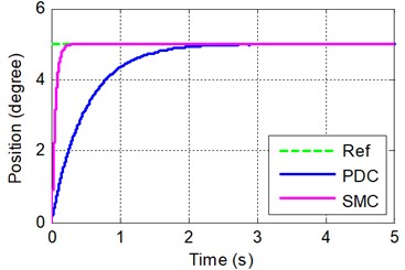
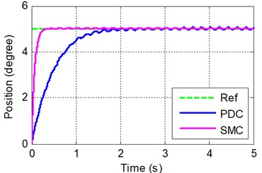
The joints A and B were acted by a step input of 5-degree in the same time. Fig. 7(a) and (b) show the step responses of the PDC and SMC of Joints A and B respectively.
For step input, the adjusting time of both joints of PDC are about 2 seconds and of SMC are only 0.2 seconds. This implicates that the SMC responds more quickly than the PDC.
Fig. 7The step response simulation of PDC and SMC
a) Joint A
b) Joint B
4.3. Sinusoid response
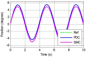
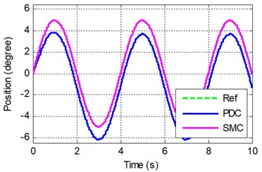
The desired trajectory of each joint is chosen to be a sine function expressed by Eq. (31). The joints A and B were acted by the trajectories in the same time. Fig. 8(a) and (b) show the sinusoid responses of the PDC and SMC of joint A and B respectively:
θd2=5sin(0.5πt),
where θ1 and θ2 are the desired angles of joint A and B, respectively.
Fig. 8The sinusoid response simulation of PDC and SMC
a) Joint A
b) Joint B
For sinusoid input, the position tracking of both joints of the PDC have obvious steady state errors and phase difference.
The simulation shows that the influence of the friction torque and disturbance of the load torque and inertia are effectively suppressed by SMC which has a strong adaptive ability to input signals. This implicates that the SMC has higher dynamic tracking precision, static precision and stronger robustness than the PDC.
5. Experiments and discussions
5.1. Experiment preparation
The speed and acceleration of the joints must be available for the feedback signals of the control system. Theoretically, speed signal can be obtained only by taking the first-order derivative of the displacement signal, and acceleration signal by the second-order derivative. However, only the signal expressed by analytic formula can be used for mathematically calculating its first or higher orders derivatives. The signal measured by sensor can’t be mathematically taken the derivatives because it has no analytic formula. Adopted in this experiment to evaluate the speed and acceleration is a third order nonlinear integration chain differentiator which has multiple integration structure and high noise suppression capability and its form is expressed as [31]:
with:
where a1= 10, a2= 10, a3= 10, α1= 1, α2= 1, α3= 1, ε= 0.01.
A first order low pass filter 1/(0.02 s + 1) is added to the second derivative output to eliminate the excessive amount of noise.
Fig. 9RTW xPC target real-time control platform principle diagram
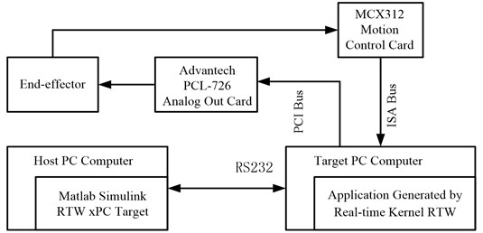
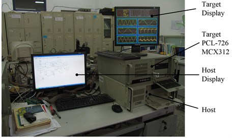
RTW xPC target real-time control platform principle diagram is shown in Fig. 9. In the experiment, Advantech PCL-726 analog output card is used to generate the control signal, and MCX312 motion control card is used for collecting the position signal from the encoder. PLC-726 can be directly driven by the corresponding module in the I/O module library of xPC target. MCX312 isn’t included in the module library and its driver must be written. In target system, the device driver must be written using C MEX S function which is a kind of S function written using C. The real-time control experiment platform based on RTW xPC target environment is shown in Fig. 10.
Fig. 10RTW real-time experiment platform
The symbolic function in the SMC expressed by Eq. (18) is replaced by a saturation function to form a quasi-sliding mode controller for reducing the chattering which is brought naturally by the SMC in the experimental system. The new control strategy is described as:
5.2. Experiment results and comparison
Because an obvious phase lag and a steady state error appeared in the sinusoidal response of the PDC, which made it difficult to achieve accurate tracking. The experiments were only carried out using SMC and MRAC.
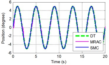
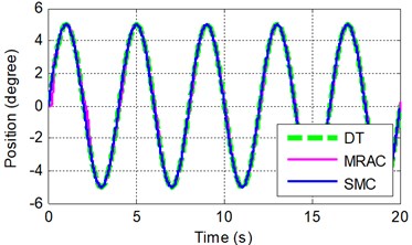
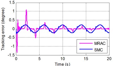
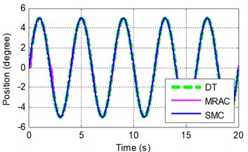
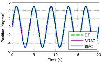
The desired trajectory of each joint is first chosen to be a sine function expressed by Eq. (31) and the joints A and B were triggered in the same time during the experiments. Fig. 11(a) and (b) show the sinusoidal responses of the MRAC and SMC of joints A and B respectively.
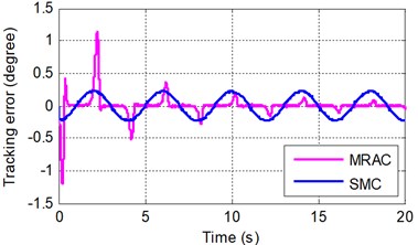
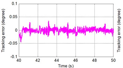
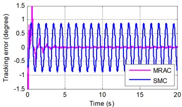
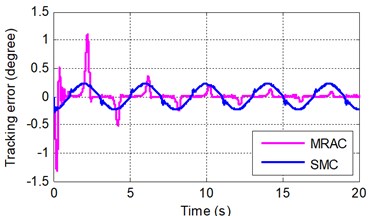
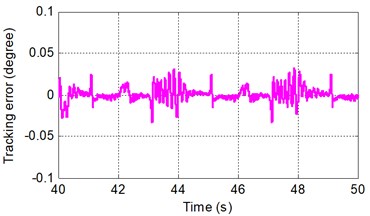
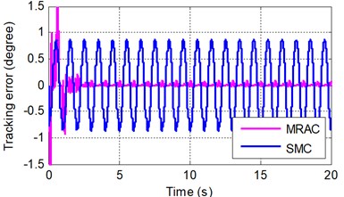
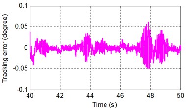
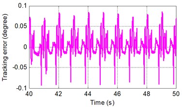
Fig. 12 shows the tracking errors of both MRAC and SMC. Fig. 13 shows the tracking error of the MRAC after the adaptive process.
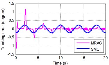
A short phase lag was present in trajectory tracking of the SMC, whilst the trajectory yielded by the MRAC coincided with the desired trajectory and had much less error after the initial transient than did the SMC. And the tracking error of the MRAC became smaller and smaller with the adaptive process while that of the SMC presented a sinusoidal wave with a constant amplitude. After the adaptive process, the tracking error of the MRAC is pretty less than that of the SMC.
Fig. 11Sinusoidal tracking at frequency of A 0.5π rad/s and B 0.5π rad/s
a) Joint A
b) Joint B
Fig. 12Sinusoidal tracking error at frequency of A 0.5π rad/s and B 0.5π rad/s
a) Joint A
b) Joint B
Fig. 13Sinusoidal tracking error under SMRC at frequency of A 0.5π rad/s and B 0.5π rad/s
a) Joint A
b) Joint B
In order to further validate the dynamic performances of the MRAC and SMC, three other experiments were carried out in which the desired trajectory of each joint is then set to be a sine function expressed by Eqs. (35)-(37) with different frequencies from the first experiment, and the joints A and B were triggered in the same time during the experiments as well:
θd2=5sin(0.5πt),
θd2=5sin(2πt),
θd2=5sin(2πt).
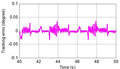
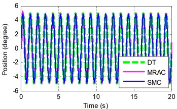
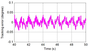
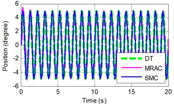
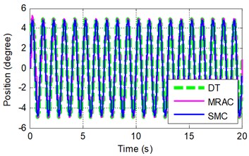
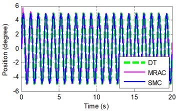
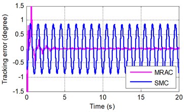
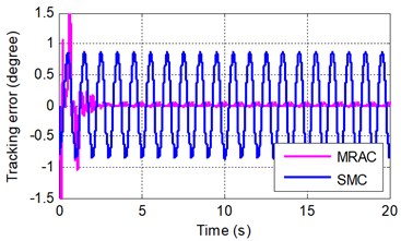
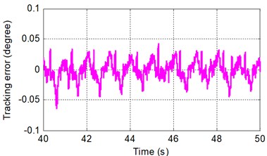
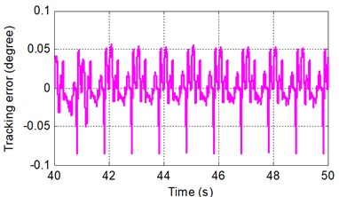
Figs. 14, 17 and 20 show the sinusoidal responses of the MRAC and SMC of joints A and B under different frequencies. Figs. 15, 18 and 21 show the tracking error of both MRAC and SMC. Figs. 16, 19 and 22 show the tracking error of the MRAC after the adaptive process.
Fig. 14Sinusoidal tracking at frequency of A 2π rad/s and B 0.5π rad/s
a) Joint A
b) Joint B
Fig. 15Sinusoidal tracking error at frequency of A 2π rad/s and B 0.5π rad/s
a) Joint A
b) Joint B
Fig. 16Sinusoidal tracking error under SMRC at frequency of A 2π rad/s and B 0.5π rad/s
a) Joint A
b) Joint B
Fig. 17Sinusoidal tracking at frequency of A 0.5π rad/s and B 2π rad/s
a) Joint A
b) Joint B
Fig. 18Sinusoidal tracking error at frequency of A 0.5π rad/s and B 2π rad/s
a) Joint A
b) Joint B
Fig. 19Sinusoidal tracking error under SMRC at frequency of A 0.5π rad/s and B 2π rad/s
a) Joint A
b) Joint B
Fig. 20Sinusoidal tracking at frequency of A 2π rad/s and B 2π rad/s
a) Joint A
b) Joint B
Fig. 21Sinusoidal tracking error at frequency of A 2π rad/s and B 2π rad/s
a) Joint A
b) Joint B
With the frequency of the desired trajectory increasing, a short phase lag was yet present in tracking of the SMC, whilst the trajectory yielded by the MRAC still coincided with the desired trajectory and had much less error after the initial transient than did the SMC. And the tracking error of the MRAC converged faster than the first experiment with the adaptive process, but that of the SMC changed in a sinusoidal fashion with a bigger constant amplitude than the first experiment. After the adaptive process, the tracking error of the MRAC does not increase obviously with the frequency increase of the desired trajectory compared with the first experiment.
Fig. 22Sinusoidal tracking error under SMRC at frequency of A 2π rad/s and B 2π rad/s
a) Joint A
b) Joint B
However, the performance of MRAC in the initial adaptive process (first five seconds) is worse than SMC. In the future work, a combination of MRAC and SMC will be proposed to tackle this problem.
6. Conclusions
In robotic control systems, nonlinearity and disturbances such as friction and system parameter variations may severely limit the performance of control. In this paper, the details of the robotic drilling end-effector, the dynamical model and control architecture of the normal adjustment system were presented. By using computation torque control method, a proportional and differential controller (PDC) and a sliding mode controller (SMC) were proposed respectively. Simulation results show that the SMC has better tracking performance than the PDC. To further improve the dynamical control quality, a model reference adaptive controller (MRAC) was developed. A real-time control experiment platform is established in xPC target environment based on MatLab RTW to verify the proposed control scheme and simulation results. Experiment performed on the designed robotic end-effector verified that the MRAC achieves tracking within a desired precision. It was showed that the PDC exhibits the worst performance. And though the simulation results indicated that the SMC presents fine, the experiment results presented that it is unmanageable and cannot meet the desired effect. Comparisons of SMC with PDC and MRAC with SMC respectively clarify that the MRAC has comparatively strong robust and an excellent advantage of adaptiveness to disturbance and parameter variations.
In future work, we will combine SMC with MRAC to improve the tracking precision of the MRAC in the initial adaptive transient.
References
-
DeVlieg R., Todd S. Applied accurate robotic drilling for aircraft fuselage. SAE International Journal of Aerospace, Vol. 3, 2010, p. 180-186.
-
Zhu W., Qu W., Cao L., et al. An off-line programming system for robotic drilling in aerospace manufacturing. The International Journal of Advanced Manufacturing Technology, Vol. 68, Issues 9-12, 2013, p. 2535-2545.
-
DeVlieg R., Sitton K., Feikert E., et al. ONCE (one-sided cell end effector) robotic drilling system. SAE Technical Paper, No. 2002-01-2626, 2002.
-
DeVlieg R. Robotic trailing edge flap drilling system. SAE Technical Paper, No. 2009-01-3244, 2009.
-
Bi S. S., Liang J. Robotic drilling system for titanium structures. The International Journal of Advanced Manufacturing Technology, Vol. 54, Issues 5-8, 2011, p. 767-774.
-
Wang Z., Qin X., Bai J., et al. Design and implementation of multifunctional automatic drilling end effector. IOP Conference Series: Materials Science and Engineering, Vol. 187, 2017, p. 012032.
-
Liang J., Bi S. S. Design and experimental study of an end effector for robotic drilling. The International Journal of Advanced Manufacturing Technology, Vol. 50, Issues 1-4, 2010, p. 399-407.
-
Devlieg R. High-accuracy robotic drilling/milling of 737 inboard flaps. SAE International Journal of Aerospace, Vol. 4, 2011, p. 1373-1379.
-
Yuan P. J., Wang T., Ma F., et al. A design and simulation of aircraft drilling end-effector based on bionics. IEEE Conference on Multisensor Fusion and Integration for Intelligent Systems, 2012.
-
Zhan Q., Wang X. Hand-eye calibration and positioning for a robot drilling system. The International Journal of Advanced Manufacturing Technology, Vol. 61, Issues 5-8, 2012, p. 691-701.
-
Zhu W., Mei B., Yan G., et al. Measurement error analysis and accuracy enhancement of 2D vision system for robotic drilling. Robotics and Computer-Integrated Manufacturing, Vol. 30, Issue 2, 2014, p. 160-171.
-
Tian W., et al. Auto-normalization algorithm for robotic precision drilling system in aircraft component assembly. Chinese Journal of Aeronautics, Vol. 26, Issue 2, 2013, p. 495-500.
-
Yu L., et al. Research on surface normal measurement and adjustment in aircraft assembly. Precision Engineering, Vol. 50, 2017, p. 482-493.
-
Yuan P., et al. The attitude adjustment algorithm in drilling end-effector for aviation. Advances in Mechanical Engineering, Vol. 8, Issue 1, 2016, p. 1-9.
-
Gray T., Orf D., Adams G. Mobile automated robotic drilling, inspection, and fastening, SAE Technical Paper, No. 2013-01-2338, 2013.
-
Zhang Q., Xiao J., Wang G. Neural network-based compensation control for trajectory tracking of industrial robots. Australian Journal of Mechanical Engineering, Vol. 13, Issue 1, 2015, p. 22-30.
-
Cheah C. C., Li X., Yan X., et al. Simple PD control scheme for robotic manipulation of biological cell. IEEE Transactions on Automatic Control, Vol. 60, Issue 5, 2015, p. 1427-1432.
-
Bartolini G., et al. A survey of applications of second-order sliding mode control to mechanical systems. International Journal of control, Vol. 76, Issues 9-10, 2003, p. 875-892.
-
Sabanovic A. Variable structure systems with sliding modes in motion control – a survey. IEEE Transactions on Industrial Informatics, Vol. 7, Issue 2, 2011, p. 212-223.
-
Hung J. Y, Gao W. B., Hung J. C. Variable structure control: A survey. IEEE Transactions on Industrial Electronics, Vol. 40, Issue 1, 1993, p. 2-22.
-
Fallaha C. J., Saad M., Kanaan H. Y., et al. Sliding-mode robot control with exponential reaching law. IEEE Transactions on Industrial Electronics, Vol. 58, Issue 2, 2011, p. 600-610.
-
Yechiel O., Guterman H. A survey of adaptive control. International Robotics and Automation Journal, Vol. 3, Issue 2, 2017, p. 0053.
-
Zhang D., Wei B. A review on model reference adaptive control of robotic manipulators. Annual Reviews in Control, Vol. 43, 2017, p. 188-198.
-
Pourseif T., Andani M. T., Ramezani Z., et al. Model reference adaptive control for robot tracking problem: design & performance analysis. International Journal of Control Science and Engineering, Vol. 7, Issue 1, 2017, p. 18-23.
-
Landau I. D. A survey of model reference adaptive techniques – theory and applications. Automatica, Vol. 10, Issue 4, 1974, p. 353-379.
-
Barkana I. Simple adaptive control – a stable direct model reference adaptive control methodology – brief survey. International Journal of Adaptive Control and Signal Processing, Vol. 28, Issues 7-8, 2014, p. 567-603.
-
Olsson H., Åström K. J., De Wit C. C., et al. Friction models and friction compensation. European Journal of Control, Vol. 4, Issue 3, 1998, p. 176-195.
-
Chacko V., Khan Z. A. Dynamic simulation of a mobile manipulator with joint friction. Tribology in Industry, Vol. 39, Issue 2, 2017, p. 152-167.
-
Meshram P. M., Kanojiya R. G. Tuning of PID controller using Ziegler-Nichols method for speed control of DC motor. International Conference on Advances in Engineering, Science and Management, 2012, p. 117-122.
-
Pisano A., Usai E. Sliding mode control: A survey with applications in math. Mathematics and Computers in Simulation, Vol. 81, Issue 5, 2011, p. 954-979.
-
Wang X., Chen Z., Yuan. Z. Design and analysis for new discrete tracking-differentiators. Applied Mathematics-A Journal of Chinese Universities, Vol. 18, Issue 2, 2003, p. 214-222.
Cited by
About this article
This work is supported by National Natural Science Foundation of China (51765031) and Natural Science Foundation of Gansu Province (1508RJZA075), China.

