Abstract
Regenerative self-excited vibrations (chatter) often occur in boring operation due to low stiffness of a slender cantilever holder of a tool. These vibrations lead to significant defects of a machined surface and cutting tool damages. The new chatter suppression method is proposed in the paper. Displacement signal measured in the direction which is orthogonal to machined surface is used for generating a control action in the feed direction. Linear proportional control law is applied. Mathematical model of boring process dynamics with control has been developed for validation of the proposed method efficiency and searching better values of feedback gain.
1. Introduction
The problem of self-excited vibrations is one of the most important in metal cutting. Hard-to-machine workpiece material and insufficient tool stiffness redouble this issue. These vibrations (commonly named as chatter) can decrease the tool life and the quality of machined surface [1]. That’s why the solution of this problem will bring the increase in the productivity of manufacturing process. The following study is concerned with the boring of inner cylindrical surface which is greatly influenced by chatter.
Chatter is mainly caused by the regenerative effect in cutting process [1, 2]. This effect occurs because of the following: a cutting tool at each moment of time is processing not only an initial workpiece surface but also its fragments obtained at previous tool passes. The variable cutting force will appear and there will be energy supply to the oscillating system under certain conditions. This energy supply will excite chatter. As chatter vibrations are inherent but unwanted for metal cutting many researches are aiming to analyze methods of chatter suppression [3-15] and chatter prediction [16-23].
There are two conventional approaches to chatter prediction:
1) Construction of stability diagrams in system parameters space;
2) Numeric integration of dynamic model equations and subsequent analysis of solution in time domain.
The first approach is based on derived delayed linearized differential equations. They allow to investigate non-perturbed motion stability. As for the second approach, it requires high computational costs. Nevertheless, the advantage of this method lies in fact that a lot of important nonlinear effects can be taken into consideration. A possible tool exit from material in case vibration magnitudes are too high [16], a nonlinear cutting forces dependence on a cut-off thickness [17], energy dissipation on a tool flank face [18], complicated 3D geometry of a tool and of a workpiece [19, 20], variable dynamic properties of a workpiece [19] are examples of these nonlinear effects.
We turn our attention to chatter suppression. There are passive and active chatter suppression strategies. The increase of the system stiffness and special dampers are applied in case of the passive strategy to eliminate the negative effect of chatter. Active strategies are based on the application of a control system. The system suppresses vibrations using actuator and embedded measurement sensor feedback [24].
Let’s review active vibration control strategies which were applied by different investigators in case of turning and boring processes. There are two most widely used strategies. These are spindle speed modulation and active control of tool displacement. Yilmaz [3] applied stochastic low-frequency spindle speed modulation. The approach of sinusoidal spindle speed modulation investigated by Insperger and Stepan [4] showed better results. Shiraishi and Kume [5] were the first investigators who applied tool position control to suppress chatter. They used feedback that is proportional to vibrational displacement and vibrational velocity. The last two values were measured instantaneously and with one revolution period delay (PD-control with delay). The performed experiments proved that implementation of the tool position control decrease the chatter amplitude. Hajikolaei [8] investigated the efficiency of applying both the spindle speed modulation and adaptive tool displacement control to suppress chatter. Experiments were not carried out during the research. The turning process was simulated instead. The simulation verified the algorithm and proved high efficiency of joint use of approaches. It is needed to mention that the direction of applied control action is the same as direction of measured data in all researches where the strategy of tool position control was applied.
In this paper, we shall present a new method of chatter suppression in the process of cylindrical surface boring. The method applies tool displacement control in feed direction which is based on the measured displacement in the direction that is normal to workpiece cylindrical surface. The control signal is transferred to instrument by a piezo actuator embedded into tool support. Efficiency of the proposed strategy is investigated basing on the special nonlinear mathematical model of the boring process dynamics.
The paper is organized as follows. Section 2 describes proposed chatter suppression strategy including possible schematic design of tool holder, control circuit and control law. The 3D mathematical model of boring dynamics with control circuit and geometrical models of tool and workpiece are described in the Section 3. Simulation results and its discussion are adduced in the Section 4. Section 5 contains conclusion.
2. Description of chatter suppression strategy
Fig. 1 shows the process of cylindrical surface boring with proposed chatter suppression system. The cantilever boring bar radial flexibility greatly exceeds axial one. Kinematic excitation of the tool vibrations in the feed direction z will suppress vibrations in the direction which is orthogonal to workpiece surface. Besides, oscillations in z direction do not influence machining accuracy and surface finish. At the same time the imposed vibrations can affect chip size and stabilize oscillations in radial direction.
Fig. 1Schematic design of chatter suppression system. ur – measured radial displacement of the tool, f – feed, uz – axial displacement of the tool implied by the piezo actuator
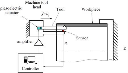
A piezoelectric actuator is used for displacement control of the tool. The actuator elongates under applied electric voltage and the cutter receives additional displacement uz. The piezo actuator elongation is proportional to the voltage within certain operational range.
The signal ur measured by the sensor, as shown in Fig. 1, is used to calculate the control signal uz. The linear control law is proposed:
where uz [mm] – axial displacement of the actuator, k1> 0 – displacement feedback gain, ur [mm] – measured tool displacement in the direction orthogonal to workpiece surface (Fig. 1).
Then the amplified control signal is transmitted to the piezo actuator which elongates and, therefore, tool tip will have the additional axial displacement uz.
Let’s consider mechanism of the proposed vibration suppression strategy. Let’s assume that displacement ur of the tool is positive, or directed upwards (see Fig. 1) into material, at the specific point of time. Chip section area increases at that point of time and cutting force also increases. According to (1) actuator moves the tool towards the negative direction of axis z. This additional displacement is opposite to feed direction and decreases the uncut chip section area and cutting force. If the displacement ur is directed out of material (negative r direction) actuator moves the tool in positive z direction-into material. Thereby actuator operation with negative feedback leads to decrease cutting force oscillations and consequently to decrease energy supply caused by the regenerative effect.
It should be mentioned that the proposed idea is applicable both for turning and boring operations as the equations of motion for both process models are similar. The values of feedback gain k1 may be chosen based on the simulation results or after preliminary experiments.
3. Mathematical model
Mathematical model of boring process is similar to [20] and consists of: 1) dynamic models of tool and workpiece, 2) model of cutting forces, 3) geometric model of the process used for uncut chip thickness computation and new surface generation. The workpiece is assumed to be much stiffer than the tool and its vibrations are neglected. The simulation is performed in time domain.
Dynamic model of tool. It’s assumed that tool can be reduced to a single DOF system presented by the schematic model, as shown in Fig. 2. The equation of tool vibrations in radial direction ur is:
where m [t] – reduced tool mass, b [N·s/mm] – damping coefficient, k [N/mm] reduced tool stiffness in radial direction, Fr(t) – radial component of cutting force applied to the tool (N), which nonlinearly depends on the relative position of tool cutting edge and machined surface.
The tool displacement in axial direction is defined by feed motion f and the additional displacement given by actuator uz Eq. (1). Deformations of tool and its holder in axial and circumferential directions are ignored.
It’s convenient to use the dimensionless damping coefficient as input parameter which is expressed:
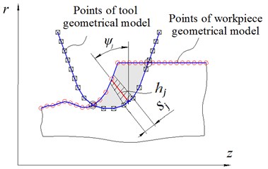
Model of cutting forces. Tool cutting edge is modeled as a set of line segments, as shown in Fig. 3, which quantity and lengths are chosen to satisfy the calculation accuracy. Radial component Fr of cutting force is determined as a sum of elementary cutting forces applied to each line segment of the cutting edge geometric model:
where Frj is computed for each jth line segment of the cutting edge according to the Eq. (4):
where sj [mm] – length of jth line segment; hj [mm] – uncut chip thickness, which computation is described below; ψj – angle between jth line segment and radial direction (Fig. 3); H() – Heaviside step function; Kc [MPa], Ke [N/mm] – empirical coefficients, depending mainly on workpiece material. These coefficients are taken for steel C45 [21].
Fig. 2Schematic model of tool dynamic. Fc – distributed cutting forces
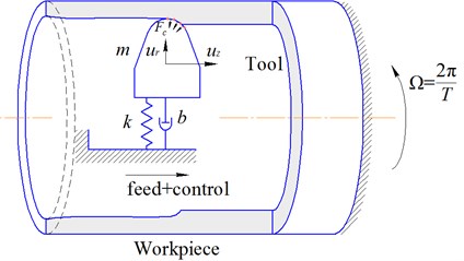
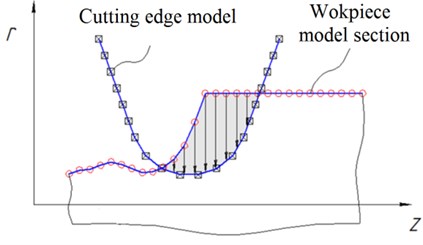
Fig. 3Illustration for algorithm of uncut chip thickness computation for line segment of the cutting edge geometric model
Geometric model includes cutting edge geometric model (described above), workpiece surface geometric model, algorithms of uncut chip thickness computation and new surface generation.
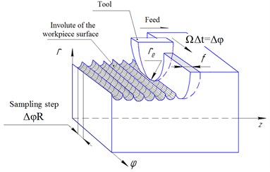
The workpiece surface is modeled as a cylinder involute which is discretized in axial and circumferential directions (Fig. 4). The time step of integration is chosen so that it corresponds to the circumferential sampling step of surface model:
where Ω [rad/s] – speed of the workpiece rotation, ∆ [s] – time step of integration, [mm] – radius of the workpiece, [rad] – angular sampling step of the surface model.
Thereby at every discrete time moment the tool cutting edge is situated in the plane of the workpiece surface model discretization (one such section is depicted in Figs. 3, 4(b).
Fig. 4Scheme of machined surface formation modeling
a)
b)
Coordinates of point of the cutting edge model at each time moment are defined as a sum of initial coordinates, displacement due to feed, actuator elongation and tool model displacement :
where , [mm]-actual coordinates of point ; , [mm] – initial coordinates of the point; [s] – simulation time.
The uncut chip thickness is determined as a distance from th segment of the cutting edge to the machined surface (Fig. 3). If the segment is out of material, 0.
If the tool is emerged in material at the end of current time step, material is cut and surface model should be modified. The surface model radial coordinates are recalculated as shown in Fig. 4(b).
Fig. 5Algorithm of simulation in time domain
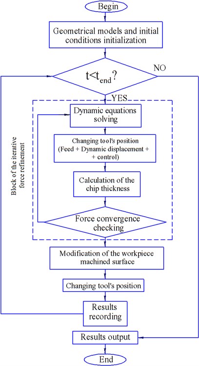
Algorithm of simulation. At each simulation point of time the instantaneous uncut chip thickness is computed. Then cutting force is calculated using Eq. (4). The Eq. (2) is integrated at current time interval considering cutting force at beginning and end of the interval. The initial conditions (vibrational displacement, vibrational velocity) and cutting force at the beginning of each time step are equal to its values at the end of previous time step. The specified steps are being iterated till convergence condition is satisfied. After the solution has been converged at current time step the tool model is displaced to the next step considering its calculated dynamic displacement, feed value and additional axial displacement . At the same time workpiece surface model is modified taking into account cut material. The algorithm of simulation in time domain is presented in Fig. 5.
4. Simulation results and discussion
The simulation of boring process dynamics was performed for the purpose of efficiency estimation of the proposed chatter suppression method. Several cases were analyzed: without control and with control with different values of feedback gain . Fig. 6 shows the shape of cutting edge. Parameters of tool and workpiece, coefficients of tool dynamic model and cutting force model are represented in Table 1.
Table 1Parameters of the process simulation
Parameter | Value | |
Natural frequency of tool in -direction | 426,26 Hz | |
Dimensionless damping coefficient | 0,1 | |
Cutting force coefficient | 1437 N/mm2 | |
Cutting force coefficient | 37,7 N/mm | |
Fillet radius of cutting edge | 1,2 mm | |
Length of straight segment of cutting edge | 20mm | |
Angle between straight segments of cutting edge | 45° | |
Depth of cutting | 0.4 mm | |
Total amount of line segments in cutting edge model | 150 | |
Length of the workpiece | 150 mm | |
Radius of the workpiece | 75 mm | |
Total amount of points in workpiece model in tangential direction | 600 | |
Total amount of points in workpiece model in axial direction | 900 | |
Quantity of workpiece revolutions applied for modeling | 1600 | |
Feed | 0,1 mm/rev | |
Tool stiffness in -direction | 1000 N/mm | |
Cutting speed | 400 mm/min | |
Spindle speed | 849,3 RPM |
Fig. 6Geometry of cutting edge
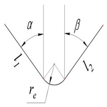
Fig. 7Surface topography after simulation without control
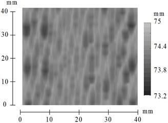
The results of process simulation without control are shown in Fig. 7 and Fig. 8. The shape of machined surface computed by simulation of boring of cylindrical workpiece with inner radius equal to 75 mm is shown in Fig. 7. It should be noted that that the quality of machined surface is low because of the significant chatter vibrations. Time history of tool displacement is presented in Fig. 8. The significant chatter vibrations arise while processing. The maximum vibration amplitude is about 5 mm. Such a high value is inadmissible and it was numerically determined without considering possible nonlinear effects, including flank face interactions, and some other limitations.
Let’s consider results of the simulation with control defined by Eq. (1). The Poincare maps were used for investigation of feedback gain influence on vibration amplitudes during processing operation. The value is depicted along abscissa axis; the local extreme values of the tool displacements are depicted by points along ordinate axis.
Fig. 8Time history of tool displacement in case without control
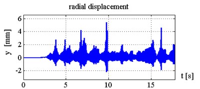
Fig. 9Poincare map of tool vibrations under control with k1= 0,…, 5
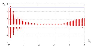
Poincare map (Fig. 9) indicates that chatter suppression is efficient when value is between 1.8 and 3.8. Machined surface topography and time histories of tool displacements and cutting forces for the cases 1; 2.5; 4 are presented in Figs. 10-15. Fig. 10 illustrates that chatter isn’t completely suppressed but steady-state vibration amplitudes are limited on the level 0.22 mm.
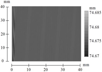
When feedback gain equals to 2.5 and 4.0 (see Figs. 12-15) suggested method of control almost eliminate chatter. The surface finish is much better in this case than when 1.
Fig. 10Time histories of tool displacements and cutting forces in case with control, k1= 1
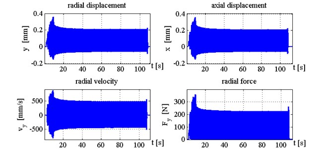
Fig. 11Surface topography after simulation with control, k1= 1
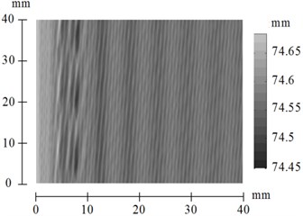
Fig. 12Time histories of tool displacements and cutting forces in case with control, k1= 2.5
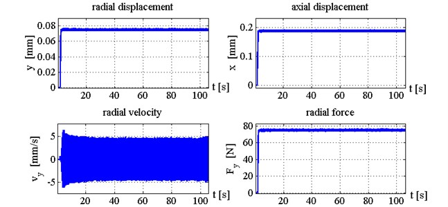
Fig. 13Surface topography after simulation with control, k1= 2.5
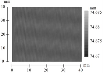
Fig. 14Time histories of tool displacements and cutting forces in case with control, k1= 4
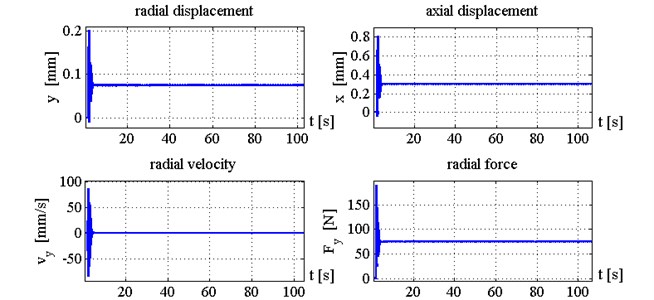
Fig. 15Surface topography after simulation with control, k1= 4
5. Conclusions
The algorithm of chatter suppression in boring process is proposed and investigated in the paper. The process control by displacement feedback is used. The mathematical simulation of boring dynamics was performed for several cases: without control and with control for different values of feedback gain. The range of values of feedback gain providing efficient suppression of vibrations was defined by the numerical simulations. 3D machined surfaces geometry and time histories of the tool displacements and cutting forces were computed. Analysis of computed surface finish showed that the proposed chatter suppression system greatly improves quality of the boring and machined surface.
References
-
Tobias S. A. Machine Tool Vibration. Blackie and Sons Ltd., Glasgow, 1965.
-
Altintas Y., Weck E. Chatter stability of metal cutting and grinding. CIRP Annals – Manufacturing Technology, Vol. 53, 2004, p. 619-642.
-
Yilmaz A., Al-Regib E., Ni J. Machine tool chatter suppression by multilevel random spindle speed variation. Journal of Manufacturing Science and Engineering, Vol. 124, 2002, p. 208-216.
-
Insperger T., Stepan G. Stability analysis of turning with periodic spindle speed modulation via semi-discretisation. Journal of Vibration and Control, Vol. 10, 2004, p. 1835-1855.
-
Shiraishi M., Kume E. Suppression of machine-tool chatter by state feedback control. CIRP Annals – Manufacturing Technology, Vol. 37, Issue 1, 1988, p. 369-372.
-
Moradi H., Movahhedy M. R., Vossoughi G. R. Robust control strategy for suppression of regenerative chatter in turning. Journal of Manufacturing Processes, Vol. 11, Issue 2, 2009, p. 55-65.
-
Xiao M., Karube S., Soutome T., Sato K. Analysis of chatter suppression in vibration cutting. International Journal of Machine Tools and Manufacture, Vol. 42, 2002, p. 1677-1685.
-
Hajikolaei K. H., Moradi H., Vossoughi G., Movahhedy M. R. Spindle speed variation and adaptive force regulation to suppress regenerative chatter in the turning process. Journal of Manufacturing Processes, Vol. 12, Issue 2, 2010, p. 106-115.
-
Pratt J. R., Nayfeh A. H. Design and modeling for chatter control. Nonlinear Dynamics, Vol. 19, Issue 1, 1999, p. 49-69.
-
El-Sinawi A. H., Kashani R. Improving surface roughness in turning using optimal control of tool’s radial position. Journal of Materials Processing Technology, Vol. 167, Issue 1, 2005, p. 54-61.
-
Chen F., Lu X., Altintas Y. A novel magnetic actuator design for active damping of machining tools. International Journal of Machine Tools and Manufacture, Vol. 85, 2014, p. 58-69.
-
Kakinuma Y., Enomoto K., Hirano T., Ohnishi K. Active chatter suppression in turning by band-limited force control. CIRP Annals – Manufacturing Technology, Vol. 63, Issue 1, 2014, p. 365-368.
-
Matsubara A., Maeda M., Yamaji I. Vibration suppression of boring bar by piezoelectric actuators and LR circuit. CIRP Annals – Manufacturing Technology, Vol. 63, Issue 1, 2014, p. 373-376.
-
da Silva M. M., Venter G. S., Varoto P. S., Coelho R. T. Experimental results on chatter reduction in turning through embedded piezoelectric material and passive shunt circuits. Mechatronics, Vol. 29, 2015, p. 78-85.
-
Munoa J., Beudaert X., Dombovari Z., Altintas Y., Budak E., Brecher C., Stepan G. Chatter suppression techniques in metal cutting. CIRP Annals – Manufacturing Technology, Vol. 65, Issue 2, 2016, p. 785-808.
-
Tlusty J., Ismail F. Basic non-linearity in machining chatter. CIRP Annals – Manufacturing Technology, Vol. 30, Issue 1, 1981, p. 299-304.
-
Budak E. Mechanics and Dynamics of Milling Thin Walled Structures. Doctoral Dissertation, University of British Columbia, 1994.
-
Tunc L.T., Budak E. Effect of cutting conditions and tool geometry on process damping in machining. International Journal of Machine Tools and Manufacture, Vol. 57, 2012, p. 10-19.
-
Kiselev I., Voronov S. Methodic of rational cutting conditions determination for 3-D shaped detail milling based on the process numerical simulation. International Conference on Multibody Systems, Nonlinear Dynamics, and Control, 2014.
-
Lazoglu I., Atabey F., Altintas Y. Dynamics of boring processes: Part III – time domain modeling. International Journal of Machine Tools and Manufacture, Vol. 42, 2002, p. 1567-1576.
-
Sortino M., Totis G., Prosperi F. Development of a practical model for selection of stable tooling system configurations in internal turning. International Journal of Machine Tools and Manufacture, Vol. 61, 2012, p. 58-70.
-
Budak E., Ozlu E. Analytical modeling of chatter stability in turning and boring operations. A multidimensional approach. Annals of the CIRP, Vol. 53, 2007, p. 401-404.
-
Urbikain G., Fernandez A., Lopez de Lacalle L. N., Gutierrez M. E. Stability lobes for general turning operations with slender tools in the tangential direction. International Journal of Machine Tools and Manufacture, Vol. 67, 2013, p. 35-44.
-
Gouskov A., Voronov S., Ivanov I., Nikolaev S., Barysheva D. Investigation of vibratory drilling model with adaptive control. Part 1: control of cutting continuity index. Journal of Vibroengineering, Vol. 17, Issue 7, 2015, p. 3702-3714.
Cited by
About this article
The research was funded by the financial support of Ministry of Education and Science, NIR N 9.1073.2014K under the design part of the State-guaranteed order in scientific research area.

