Abstract
In order to accurately study the dynamic characteristics of soft clay under vibrating loads, the classical double-yield surface model is improved in this paper, and it is introduced time effect which is proposed by Borja to build a constitutive model. The constitutive model considers creep and is suitable for analysis on dynamic characteristics of soft clay. Next, GDS dynamic triaxial experiment is carried out in the indoor, and validation analysis is conducted by means of the experimental data. In order to verify its actual effect, the improved model is applied to settlement calculation of soft clay during subway operation under vibrating loads, and then the calculation result is compared with the experimental data. It shows that the improved double-yield surface model which considers time effect can describe the dynamic deformation characteristics of soft clay more reasonably. And the proposed model is suitable for analysis on settlement of soft clay under vibrating loads of subway.
1. Introduction
Soft clay refers to fine-grained soil which is mainly grey in appearance, with its natural void ratio more than 1.0 and its water content larger than liquid limit [1]. The partial subway foundation is located in muddy clay which is soft clay with large settlement [2]. Under the vibrating loads of subway, soft clay will have an obvious creep phenomenon which can last for 10 years. The creep phenomenon has a huge influence and may damage the stability of subway structure [3]. In addition, the serious vibration for a long time will affect safety, water proof performance and durability of the structure. And an excessive settlement will affect the smoothness of the rail, ride comfort and the normal operation [4]. Liu [5] researches settlement during subway operation, and then he analyzes the causes of settlement and its influences. Tang [6] indicates that the subway damage is caused by the long time vibration.
References [7-9] prove that the effect of subway vibrating loads on soft clay can be simulated by means of dynamic triaxial experiment in the indoor. Meanwhile, a constitutive model with considering the characteristics of soft clay needs to be proposed, so that settlement can be calculated more accurately. There are many models currently, among which elliptic parabolic double-yield surface model has been widely used [10]. This model can reflect the dilatancy from the theory, and describe the different stress paths, but it cannot describe the creep characteristics of soft clay under vibrating loads.
The elliptic parabolic double-yield surface model is improved in this paper, with time effect taken into account. And the hysteretic deformation theory proposed by Borja is introduced into volume strain and shearing strain [11] to build an improved double-yield surface model. Next, GDS dynamic triaxial experiment is carried out in the indoor, and validation analysis is conducted by means of the experimental data. In order to verify its actual effect, the improved model is applied to settlement calculation of soft clay during subway operation under vibrating loads.
2. Building the constitutive model of soft clay under vibrating loads
2.1. Double-yield surface model
Equations of the classical elliptic parabolic double-yield surface model are shown as follows [11, 12]:
where q=√((σ1-σ2)2+(σ2-σ3)2+(σ3-σ1)2)/2 is the deviation stress. p=(σ1+σ2+σ3)/3 is the effective stress mean. Under the experimental conditions of the axial symmetry, q=σ1-σ3. p01=hεpvpa/(1-mεpv) is the hardening parameter of F1, wherein εpv is the plastic volume strain, h and m are determined by consolidation and rebound experiment. pr is the intercept of failure line qf-p on axis p. M1 is a parameter which is larger than M. p02=εps=∫√2((dεp1-dεp2)2+(dεp2-dεp3)2+(dεp3-dεp1)2)/3 is the hardening parameter of F2, wherein εps is the plastic deviation strain. a is the proportion of strain in the total deformation, and it is determined by the relation curve between volume strain and deviation strain. G is the elastic shear modulus and it can be obtained according to specifications. M2 is determined by the relation curve between the deviation stress and shear strain.
2.2. Creep characteristic
According to the hysteretic deformation theory proposed by Borja, the total strain equals to the sum of elastic strain, plastic strain and the hysteretic deformation with considering time effect. The creep strain caused by time effect consists of volume creep εtv and deviator strain creep εts, and equations are as follows:
where the superscripts such as e, p and t indicate elasticity, plasticity and creep, while the subscript such as v andsindicate volume and deviation strain.
The volume creep and deviator strain creep are substituted in the elliptic parabolic double-yield surface model to serve as the hardening parameters [11]:
where ψ indicates creep parameter which is determined by the constant pressure experiment. e is void ratio of soft clay. tv and td are calculation time. A, ¯α, ¯D and m are determined by the relation curve between creep shear strain and time. (td)t is the reference factor of time, and it is set to be 1 in this calculation. Eqs. (5) and (6) in the paper are from Eqs. (8) and (9) in reference [11]. How to determine Δt is explained in details in reference [11]. The reference points out that Δt in Eq. (5) is determined according to reading time which is made by a lot of consolidation experiments. Δt in Eq. (6) is determined according to the shear strain rate which is also made by experiments. According the method [12] put forward by some scholars, the calculation is simplified. In order to solve the viscosity shear strain εts, the viscosity volume strain εtv can be solved at first, and then the overstress ϕ=εtv/(∂F/∂p)is substituted into εts=ϕ∂Q/∂q to obtain the viscosity shear strain.
2.3. Derivation of flexibility matrix
To conveniently derive the theory, plasticity and viscidity are combined to plastic strain which is changing with time. The constitutive relation is derived by flexibility matrix according to theories of plasticity [13].
p01 is explained in Eq. (1). p01 is only the function of εpv in Eq. (1), and time effect is not taken into account. Next, the improved double-yield surface with considering time effect is put forward based on the classical double-yield surface model in this paper. As a result, p01 will be the function of εpv and time effect t:
According to Cambridge model, the following equations can be obtained:
where λ, K and ψ are parameters of Cambridge model, and they can be obtained by CU and CD experiments. p0 is the initial consolidation pressure.
In case of the instantaneous loading, the following equations will be obtained:
When the limit value of Δt in Eqs. (10) and (11) is set to be 0, the following equation will be obtained:
Eq. (12) is from Eqs. (19) and (20) in reference [11]. Derivation of the equation is explained in details in reference [11], wherein the limit value of Δt is set to be 0, and derivation is conducted based on the data limit method. Due to that the length of the paper is limited, and the detailed derivation process is not given here.
p02 is explained in Eq. (2). p02 is only the function of εps in Eq. (2), and time effect is not taken into account. Next, the improved double-yield surface with considering time effect is put forward based on the classical double-yield surface model in this paper. As a result, p02 will be the function of εps and time effect t:
The above equations are substituted into dε=[Cp]dσ. According to plastic mechanics, plasticity flexibility matrix [Cp] is made of two matrixes which are the first plasticity flexibility matrix [Cp1] and the second plasticity flexibility matrix [Cp2], respectively. Two matrixes are from derivative of Eqs. (1) and (2), respectively:
In order to solve plasticity flexibility matrix [Cp], [Cp1] and [Cp2] must be obtained firstly. According to the correlative flow theory, Eq. (1) is changed into the following type:
[Cp1] is obtained by solving derivative of Eq. (15), and then the following equation is shown:
The detailed expression of [Cp1] and A1 can be obtained by solving {∂g1/∂σ}, {∂f1/∂σ}T, F' and {∂g1/∂p}. Their expressions are shown as follows:
Then, Eqs. (17) to (19) are substituted into Eq. (16). [Cp1] and A1 are obtained finally. In the similar way, [Cp2] and A2 can be also obtained as follows:
Finally, plasticity flexibility matrix [Cp] and A are solved as follows:
3. Dynamic triaxial experiment in the indoor
3.1. Soft clay sampling process
The soft clay sampling location is near the subway station, which is buried in 9.5 m-12 m, right in soft clay layer [5]. Soft clay is sampled by thin wall sampler and static pressure method, and the quality of the sampled soft clay reaches level II. Water and soft clay acquired should be marked, packaged in time. Meanwhile, the effective quakeproof measures are taken. Finally, the samples must be sent to the laboratory in time, and vibration should be avoided during transportation. The basic parameters are acquired as shown in Table 1 through the common experiment.
Table 1Physical parameter indexes of soft clay from subway station
Item | W (%) | Gs | e0 | Es (MPa) | Ip | ρ |
Mean value | 40.3 | 2.73 | 1.1 | 2.72 | 18.2 | 1.77 |
3.2. Experimental equipment
The equipment is GDS dynamic triaxial system from British. It can apply vibrating load, as shown in Fig. 1.
Fig. 1GDS dynamic triaxial equipment
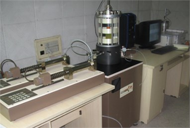
Fig. 2Sample preparation process
3.3. Sample preparation and experimental process
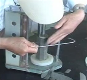
Sample preparation is carried out for soft clay from the site. The soft clay samples are cut into cylinders with the diameter of 3.8 cm and height of 8 cm before experiment, as shown in Fig. 2.
Fig. 3Vibrating loads in the vertical direction for the dynamic triaxial experiment
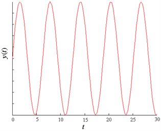
To simulate the effect of soft clay under vibrating loads of subway, sine loading is adopted, and the operation process is as follows.
Saturation stage: to increase the saturation, air exhaustion is carried out for soft clay, and then the initial saturation is tested before anti-pressure saturation. Saturation pressure and anti-pressure are 50 kPa and 45 kPa, respectively.
Solidification process: let the soil solidify under k0 status, the solidification pressure during this process is 50 kPa, 100 kPa and 200 kPa, respectively.
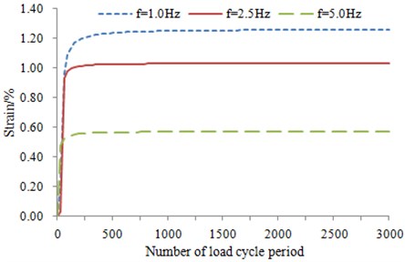
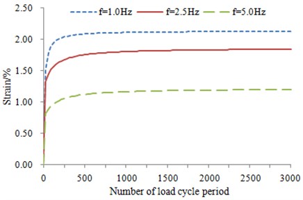
Vibrating loads: the shape of subway vibrating loads [14] is similar to sine wave, as shown in Fig. 3. The load amplitudes are set as 20 kPa, 30 kPa and 40 kPa in sequence. Frequencies are 1 Hz, 2.5 Hz and 5 Hz, respectively. Number of load cyclic period is 3000 times.
3.4. Analysis on the experimental results
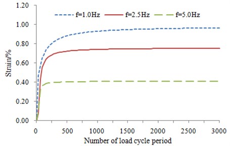
The data are acquired through dynamic triaxial experiment which is used to simulate vibrating loads of subway [15], and then analysis is carried out. In the experiment, three groups of data are tested, and each group of data is not completely the same. The interval-dot value method is used to process the experimental data, and it is an averaging process in fact. As a result, three groups of data are averaged, and the average value is taken as the final result. Based on this method, a lot of curves are obtained by means of this method, as shown in Fig. 4.
According to the above figures, the curve of the accumulated plastic strain is in exponential form, and the curves also show how the vibrating loads and loading frequency change. The accumulated strain gradually increases with the increase of the number of load cycle period, and the attenuation rules are consistent. They can all be divided into three stages. It is an elastic process which is approximate to a line at the initial stage. Then, an abrupt turn occurs, and it enters into elastic-plastic stage. Finally, it enters into the steady-state process which tends to be smooth. However, the divisions of each stage vary under the different dynamic stress amplitudes and vibration frequencies.
As the frequency increases, time of vibrating loads is shorter and shorter, and the accumulated plastic strain of the soft clay is smaller and smaller. According to the figures, the relation between the frequency and the deformation may not be a straight line. The curve corresponding to f= 1 Hz is closer to the curve corresponding to f= 2.5 Hz, while the curve corresponding to f= 5 Hz is lower.
The larger vibrating loads are, the larger the accumulated plastic deformation will be. The larger the effective pressure is, the smaller the clearance among soft clay will be, and the deformation under vibrating loads will be smaller.
4. Validation and analysis of the improved model
4.1. Determination of the basic parameters
To conveniently decide model parameter, the triaxial experiment is deemed as a test with step-by-step loading and unloading. Meanwhile, CU and CD experiments are also carried out, and their stress amplitudes are consistent with that of the triaxial experiment [16]. In addition, consolidation and rebound experiments are also conducted. According to descriptions in the isopiestic experiment specifications, the loading levels of the confining pressure should be 12.5 kPa, 25 kPa, 50 kPa, 100 kPa, 200 kPa, 400 kPa and 800 kPa. During the rebound experiment, the confining pressure is loaded to a big value at first. Then, the confining pressure is removed when the state is stable. Finally, the unloading process is stopped until the loading levels of the confining pressure in the above are realized. In the calculation of this paper, vibrating load is σs= 40 kPa, and the confining pressure is σ3= 200 kPa and f= 2.5 Hz.
1) Determination of KG and n
KG and n are 58 and 0.35 according to the Fig. 5 and some formula.
2) pr, M1, M2
According to experience, C=31.3 kPa, ϕ= 11°, pr=ccotϕ, M=6sinϕ/(3-sinϕ), M1=1.2M, M2=1.09M.
3) h and t
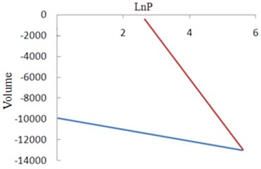
h and t are determined by the consolidation and rebound experiments in all directions, as shown in Fig. 6.
4) a is 0.2 according to experience.
Fig. 4The curve of relation between strain and number of cyclic load
a)σs= 20 kPa, σ3= 200 kPa
b)σs= 30 kPa, σ3= 200 kPa
c)σs= 40 kPa, σ3= 200 kPa
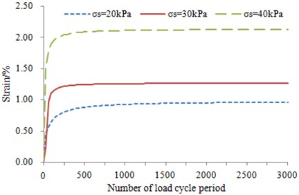
d)f= 1.0 Hz, σ3= 200 kPa
Fig. 5The curve of q-εs relation
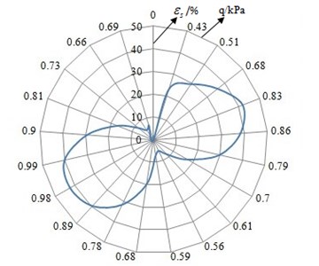
Fig. 6Curve of consolidation and rebound test
4.2. Determination of creep parameters
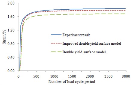
In the calculation of this paper, all the model parameters are determined as follows. KG= 62, n= 0.45, pr= 40, M1= 1.06, M2= 1.02, h= 150, t= 3.55, a= 0.32, Cα= 0.015.
The results in Fig. 7 show that three curves are consistent at the elastic stage. In the elastic-plastic stage, the model considering time effect is close to the experimental value, which proves that the improved model has good reliability.
Fig. 7Validation for the improved constitutive model
5. Engineering applications
Subway is deeply buried in the soft clay layer which is 9 m-12 m away from the ground. Settlement generated during operation is large. The subway operation company set the benchmark in 2004 to conveniently monitor settlement. The monitor period is approximate two months. Settlement at the stations is small, while settlement at the other sections is large, in particularly in the unstable settlement tank where settlement reaches 114 mm [5].
Stress of the subway foundation can be acquired through the finite element method. The subway model has too many meshes. As a result, the calculation cost will be very high and the efficiency will be also low. It is considered that the model is symmetrical. In order to improve the efficiency and speed up the convergence process, half of the model is used as the calculation model in this paper.
The subway model is divided into lining (concrete) and tunnel (soft clay). The contact problem is taken into account in this calculation. There are 120 elements and 155 nodes in the lining model, as shown in Fig. 8(a). There are 9,196 elements and 9,404 nodes in the tunnel model, as shown in Fig. 8(b). The material properties of lining are expressed by the conventional physical parameters such as elasticity modulus, density and Poisson’s ratio. The material properties of soft clay are replaced by the programs of the improved double-yield surface model. Next, the models of lining and soft clay are combined by the common node method. The model is finally obtained as shown in Fig. 10. By the above analysis, the improved double-yield surface model is organically combined with the commercial FEM software.
Lining is concrete with the thickness of 300 mm. The total horizontal length is 10D=60 m.The distance between the ground and the center of the tunnel is 12 m, the distance between the bottom and the center of the tunnel is 30 m in total.
Fig. 8Mesh model of lining and tunnel
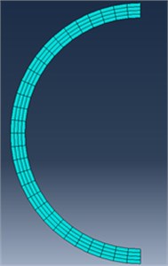
a) Mesh model of lining (concrete)
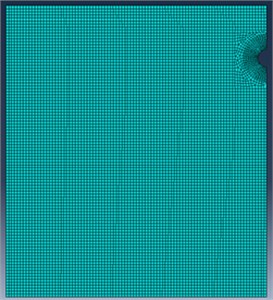
b) Mesh model of tunnel (soft clay)
The subway operates 16 hours in everyday, with one subway passing by every 4.5 minutes. The same position bears 2000 vibrations by the subway everyday and 700,000 vibrations every year. It is considered that the effect of the vibrating load on the ballast bed is uniform linear load, and the formula for its relation with time is as follows:
where P(t) is the actual wheel-rail load. i=2 is the number of subway bogies. j=2 is the number of wheels of each pair of bogies. L is the length of single subway, K= 0.7 is dispersion coefficient of calculation.
Fig. 9Diagram of vibrating loads for subway
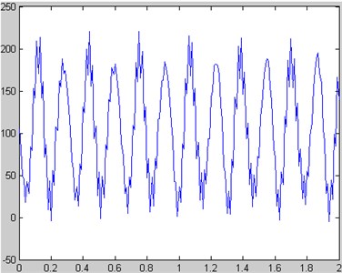
Fig. 10The finite element model of subway
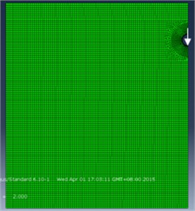
As shown in Fig. 9, the subway vibrating loads calculated are half-sine wave [17], and then they are substituted into the finite element model for the numerical simulation, as shown in Fig. 10. The arrow in Fig.10 indicates the loading direction of force.
According to the finite element model, the field of stresses with considering time effect can be obtained, as shown in Fig. 11.
Fig. 11The field of stresses with considering time effect
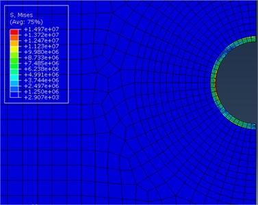
Fig. 12Relation curve between stresses and time
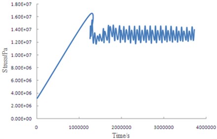
According to Fig. 11, the stress values are not uniformly distributed in the subway model. After stability, the maximum value (1.497e7 Pa) and the minimum value (2.907e3 Pa) differ greatly. The data at the maximum stress in Fig. 11 is exported to obtain the curve which is used to describe how this field changes in time, as shown in Fig. 12. It is shown in the figure that, before 1,200,641 s, stress and time show a linear relation. With time increase, the maximum value of stress is 1.663e7 Pa, and the model mainly stays at the elastic deformation stage before its stress reaches the maximum value. When the time is more than 1,200,641 s, the stress shows a stable fluctuation. At this moment, the model stays at the plastic deformation stage. The stress value is smaller than the maximum value at the elastic deformation stage.
In order to verify the engineering effect of the improved model, the double-yield surface model without considering time effect is also substituted into the commercial FEM software to calculate the field of stresses, as shown in Fig. 13. It is compared with Fig. 11. According to the comparison results, the stress value (1.497e7 Pa) with considering time effect is bigger than the stress value (3.426e6 Pa) without considering time effect. This is mainly because that time delay will generate the extra stresses. Therefore, there will be some big problems in the results when the double-yield surface model without considering time effect is directly used to analyze the actual engineering. Time effect must be taken into account in order to realize the effective analysis.
Fig. 13The field of stresses without considering time effect
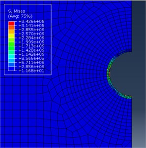
Fig. 14The curve of settlement-time of the subway
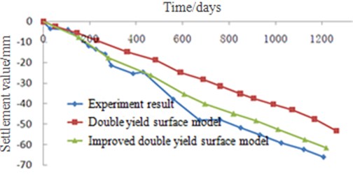
The stress calculated by the finite element method is substituted into the analytical solution of the constitutive model, and the final settlement is calculated by means of splitting summation method, as shown in Fig. 14.
Comparison and validation show that the calculation result of the improved model is basically consistent with the experimental data, which shows that the modified formulas have good applicability in the actual engineering.
6. Conclusions
The following conclusions can be obtained from the above researches.
1) The dynamic triaxial experiment in the indoor is carried out on soft clay of subway to simulate the status under vibrating loads during subway operation. The different frequencies and vibrating loads are set to acquire the relation curve between the accumulated plastic strain and number of load cycle periods, and then analysis is carried out.
2) Hysteretic deformation theory is introduced to the classical elliptic parabolic double yield surface model, and then the improved double-yield surface model with considering time effect is proposed. The improved model is reliable to calculate strain of soft clay by means of a series of analysis.
3) The improved double-yield surface model is applied to the actual engineering. The stress value of the foundation for subway is simulated by the finite element method. The settlement value during operation is calculated by means of splitting summation method, and it is compared with the experimental data. The results show that the improved model is suitable for analyzing the settlement of subway.
References
-
Li G. H., Huang T., Xi G. Y. Review of researches on settlement monitoring of metro tunnels in soft soil during operation period. Journal of Hohai University (Natural Sciences), Vol. 39, Issue 1, 2011, p. 277-284.
-
Huang G. L., Wei M., Han A. M. Analysis on the subsidence of tunnel foundation in Nanjing Yangtze River valley flat. Hydrogeology and Engineering Geology, Vol. 33, Issue 3, 2006, p. 112-116.
-
Liao S. M., Bai T. H., Peng F. L. Longitudinal settlement forms and structural response of shield tunnel. Underground Space and Engineering, Vol. 2, Issue 5, 2006, p. 765-769.
-
Ye Y. D., Zhu H. H., Wang R. L. Analysis on the current status of metro operating tunnel damage insoft ground and its causes. Underground Space and Engineering, Vol. 3, Issue 1, 2007, p. 157-160.
-
Liu F. Long-Term Settlement of Metro in Soft Ground and Its Influence on Safety. Nanjing University, Nanjing, 2013.
-
Tang Y. Q., Zhao H., Wang Y. D. Characteristics of strain accumulation of reinforced soft clay around tunnel under subway vibration loading. Journal of Tongji University (Natural Sciences), Vol. 7, Issue 1, 2007, p. 972-977.
-
Zhang X., Tang Y. Q., Zhou N. Q. Dynamic response of saturated soft clay around a subway tunnel under vibration load. China Civil Engineering Journal, Vol. 40, Issue 2, 2007, p. 85-88.
-
Tang Y. Q., Li R. J., Wang Y. D. Experimental study on strain softening of reinforced soft clay around the subway tunnel under the vibration load. Journal of Jilin University (Earth Science Edition), Vol. 39, Issue 2, 2007, p. 1-7.
-
Liu S. The Study on the Rheological Properties of Saturated Soft Clay around the Tunnel under Subway Loading. Tongji University, Shanghai, 2007.
-
Yin Z. Z. A double yield surfaces stress-strain model of soil. Chinese Journal of Geotechnical Engineering, Vol. 10, Issue 4, 1998, p. 64-71.
-
Borja R. I., Kavazanjian E. Jr. A constitutive model for the stress-strain-time behaviour of ‘wet’ clays. Geotechnique, Vol. 35, Issue 3, 1995, p. 283-298.
-
DunCan J. M., Chang C. Y. Nonlinear analysis of stress and strain in soils. Journal of Geotechnical Engineering Division, ASCE, Vol. 96, Issue 5, 1970, p. 1629-1653.
-
Zhang K. Y., Wen D. B., Ma Q. H. Three-dimensional anisotropic revision and experimental verification of elliptic parabolic double yield surface elastoplastic model. Chinese Journal of Rock Mechanics and Engineering, Vol. 32, Issue 8, 2013, p. 1692-1700.
-
Zhang Y. E., Bai B. H. The method of identifying train vibration load acting on subway tunnel structure. Journal of Vibration and Shock, Vol. 19, Issue 3, 2000, p. 68-76.
-
Huang M. S., Li J. J., Li X. Z. Cumulative deformation behavior of soft clay in cyclic un-drained tests. Chinese Journal of Geotechnical Engineering, Vol. 28, Issue 7, 2006, p. 891-895.
-
Zhang M. L., Qian J. H., Chen X. L. Tests on rheological behavior of soft soil and rheologic model. Chinese Journal of Geotechnical Engineering, Vol. 15, Issue 4, 1995, p. 54-62.
-
Feng J. H., Yan W. M. Numerical simulation for train stochastic vibration loads. Journal of Vibration and Shock, Vol. 27, Issue 2, 2007, p. 49-52.
About this article
The project is supported by the National Natural Science Foundation of China (51308234, 51408242), the Promotion Program for Young and Middle-aged Teacher in Science and Technology Research of Huaqiao University (ZQN-PY112), and the Open Research Fund of State Key Laboratory for Geo-mechanics and Deep Underground Engineering, China University of Mining and Technology (SKLGDUEK1304).
