Abstract
In this paper, the problem of automatic tuning of vibration technological machines (e.g. vibrating screens) to resonant mode is considered. The purpose of the study is to develop a control system to provide the initial resonant setup and its control, regardless parameters variations such as operating loads. To achieve this two control algorithms are proposed. The first algorithm is based on linear approximation, while the second one is based on the preliminary analysis of some relations between the system parameters. The advantages and disadvantages of the proposed algorithms are considered and the applicability limitations are determined.
1. Introduction
One of the problems in designing high-performance vibration technological machines is stabilization of the resonant mode. Resonance tuning might significantly reduce power consumption and improve the performance [1-7]. The problem of resonant tuning is associated not only with operating loads fluctuations and nonlinear mechanical characteristics, but also with the dynamic interaction of the machine and vibratory drive, in particular, the Sommerfeld effect [2, 7-12]. This problem is particularly important for the machines with asynchronous motor, which are now mainly operated in below-resonance or above-resonance modes. Obviously, this problem can be solved by application of feedback control system. The choice of control parameters and algorithms greatly depends on the mechanical system and motor drive properties.
The problem of resonant mode stabilization for the machines with the unbalanced exciter and DC motor by using feedback into the angular velocity control system is now well-developed [1, 3]. Similar problems of resonant tuning occur in the use of electromagnetic, magnetostrictive and piezoelectric exciters (see, for example, [13]), which are successfully solved by feedback inclusion into control system by means of adjusting the phase shift of the feedback signal.
Conditions of existence and stability of resonant oscillations excited in the autoresonant machine with synchronous motor are described in [2, 3], which discusses excitation of self-oscillations and oscillation control by changing the phase shift in the feedback, and proposes some schemes of the self-resonant mode implementation.
Another way to improve stability of resonant machines with high Q-factor without automatic control is based on excitation of the parametric oscillations implementing multiple combinational resonant modes [5, 14].
A large number of studies on the control of asynchronous motors are known [15-18]. However, the issue of stabilization resonant mode of the systems with asynchronous motor (the most widely used in vibration machines) is poorly understood so far and requires further development.
Designing effective control systems for resonant modes of such machines causes significant difficulties due to nonlinear interaction between electrical and mechanical subsystems as well as ambiguous relationships of the parameters.
Analysis of steady-state oscillations for technical systems with limited power motor is usually carried out considering its static characteristics [1, 2, 8]. This approach allows to easily identify main characteristics of system behavior, including the Sommerfeld effect, rotating rotor jam, frequencies and amplitudes jumps at “quasi-static” resonance zone passing.
However, calculations based on static characteristics would just approximately describe system behavior within one driving cycle (turnover). Usage of these characteristics would neither allow to identify the features of transient regimes, nor explain significant dynamic peak loads in the system.
Linearized dynamic characteristics of the motor, which take into account its intrinsic time constant and represent relations of coordinates and velocities not only with driving force (torque) but also with its derivative, are typically used to describe transient modes. However, the linearized dynamic characteristics also limit both the ability of dynamics analysis and feedback inclusion into control system.
In this work, we consider a vibrating machine in which the working body performs unidirectional oscillations caused by rotation of unbalanced exciter with asynchronous AC motor. Comparative analysis of two possible control system (CS) algorithms ensuring stability of the resonant mode is also presented.
We assume that the natural frequency of the machine is not initially known. Also any parameter of the system, such as process load, may change during operation. Therefore the CS should provide the initial resonant setup and its maintenance, regardless parameters variations.
2. Mathematical model of the machine
Design scheme of the machine is shown in Fig. 1. Platform with motor and operating loads is represented in the form of a rigid body with mass . Visco-elastic support has linear characteristics: stiffness and damping coefficient . The platform can oscillate in vertical direction only. Unbalanced exciter with asynchronous three-phase AC motor is rigidly attached to the platform. The exciter has unbalanced mass and eccentricity . The rotation of the rotor is caused by the action of electromagnetic torque . We also assume constant resistance torque . Many design schemes of machines with multiple exciters implementing unidirectional exciting force can be reduced to a similar calculation scheme. This scheme allows to identify and describe the most important dynamic features of real machines [2, 6, 7].
Fig. 1Design scheme of the mechanical system: 1 – control unit, 2 – inverter
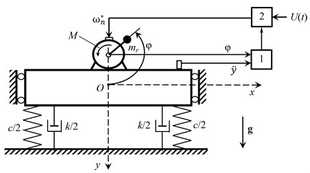
Motion of the system is considered in the fixed coordinate system . Its origin is aligned with the position of the common center of mass, and vertical axis coincides with the direction of gravity . Angle of rotation of the rotor is described by , counterclockwise from the positive direction of the axis .
Our task specific requires an adequate description of the system motion in both steady and transient modes. Therefore, in contrast to the commonly used description of the driving torque as a function of the angular velocity (static characteristics of the motor), in this paper we consider the relationship between flux linkages and currents which could be derived from voltage equilibrium conditions for all phases of the stator and rotor [18-20]. So the driving torque of the motor could be determined from the analysis of the considered relationship.
Equations of motion for the system are [21]:
here , is the reduced moment of inertia of the motor with unbalanced rotor, dots denote the total derivative with respect to time , is the number of poles of the motor, and are stator and rotor windings resistance respectively, , are column vectors of flux linkages for the stator and the rotor, is column vector of instantaneous values of the voltages in phases of the stator winding, and are amplitude and frequency of supply voltage respectively, are known matrix of inductances and , are mutual induction matrix, which are specified by the motor nameplate parameters: main inductance and leakage inductances of stator and rotor, respectively.
Thus, Eq. (1) completely describes the system oscillations excited by an unbalanced rotor of the motor. Detailed analysis of the system dynamics is given in [21].
3. Control system and algorithms
Operation principle of the control system is based on periodic measurement of the phase shift between the platform displacement and disturbing force, which at resonance must be equal to [7]. The value of the disturbing forces applied to the platform is determined by its projection on the vertical axis (Fig. 1). Therefore, as a measured parameter for this force it is natural to consider the position of the rotor, which is detected by the angular position sensor, such as, encoder. Displacement and frequency of the platform oscillations are measured by vibration sensor, for example, piezoelectric accelerometer, with subsequent double integration. Measured signals are processed in the control unit.
As a control parameter, we considered frequency of the supply voltage, applied to the motor via inverter. This method allows to adjust the rotation speed of the rotor in a wide range and to minimize energy consumption [15-18]. In this case, the main difficulty lies in choice of control algorithm, since the relationship between the phase shift and frequencies and in systems with variable load and limited power motor is not known beforehand. The numerical algorithm for determining the phase shift and the correction value of the control parameter is implemented in the control unit. The control system monitors vibrations of the platform and angular position of the unbalanced rotor. For each current time (here is index corresponding to present moment of time) when , motor speed and phase shift are computed. When:
it is believed that the system reached its steady-state mode (here is number of periods which are used to estimate steady-state fluctuations, is the ahead given accuracy). In accordance with a specified algorithm the supply frequency corresponding to the resonant mode is computed and then it is supplied to the motor. Setting up the system to the resonant mode is completed if .
To determine the correction value for control parameter in this paper we consider two possible algorithms.
Algorithm No. 1. Is based on successive approximation to the resonant frequency, when necessary change of supply frequency at each regulating step is determined from analysis of the system with unlimited power drive, for which (linearized Eq. (1)). In this case the motion of the system within each step of regulation will be determined by linear equation of the form [2, 7]:
The phase shift is determined by the solution of Eq. (2):
here:
If at any time the system has some a-priori unknown mass , and the debalance rotates with a given frequency , then we can derive the natural frequency of the system by measured phase shift from Eq. (3), which corresponds to the current mass of the system (if stiffness and damping parameters of the system are determined):
Using Eq. (4), the supply frequency which corresponds to the resonant mode could be defined as .
Setting up the system to the resonant mode was considered to be complete if the phase shift is within the control precision. Otherwise the control cycle repeats itself.
Algorithm No. 2. The idea of the algorithm is based on the preliminary analysis of the dynamics of system Eq. (1) in order to establish the relationship between the supply frequency of the motor, phase shift and eigenfrequency of the system. We call this relationship “dynamic portrait” of the system (see Fig. 2, where , , , – frequency scale factor, rad/s).
Fig. 2“Dynamic portrait” of the system
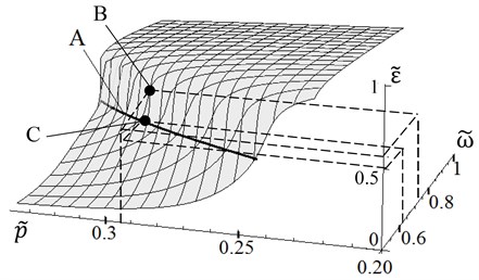
As it was in the previous case, we suppose that at some point in time mass of the system is unknown. At given supply frequency and measured phase shift the natural frequency which corresponds to the current parameters of the system is computed using the dynamic portrait (point B in Fig. 2). Using this computed natural frequency , the supply frequency which corresponds to the phase shift (point C in Fig. 2) is determined. Then this frequency is supplied to the motor through the inverter.
4. Comparative analysis of the proposed algorithms
In this paper we study the work of the proposed control algorithms under quasi-static change of the dynamic properties of the system. As a variable parameter we consider mass of the system, which can vary in an arbitrary manner, e.g. because of the fluctuations of mass of the processed medium in real processes [2, 6, 7]. In simulating the operation of the control system we considered that change of mass is determined by the piecewise linear function of time (see Fig. 3, where ). In the initial state the system is at rest. At time voltage with predetermined frequency is supplied to the electric motor. The effectiveness of the algorithms was estimated by its ability to adjust the system to the resonant mode, period of time necessary to reach resonant mode, and required number of regulation steps.
Numerical simulation was carried out for the following parameters of the mechanical system and the motor: 2.6×10⁻³ kg∙m2, 1.5 kg, 50 kg, 0.02 m, 444 kN/m, 0.5 kN∙s/m, 220 V, 0.02 N∙m, 2, 9.81 m/s2, 0.01, 5, 0.089 H, 0.156 H, 1.364 H, 56.84 Ω, 46.23 Ω.
Fig. 3Change of the platform mass
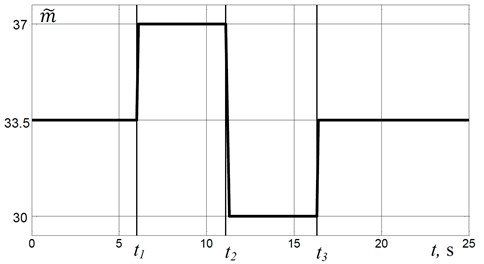
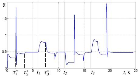
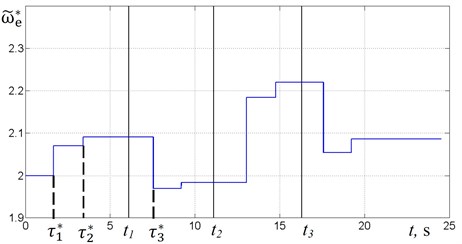
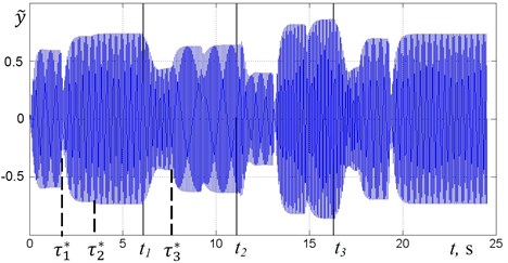
Fig. 4 shows the graphs of the phase shift , the supply frequency and displacement for the change of mass (Fig. 3) in case of using the algorithm No. 1.
After the motor starts, CS determines time corresponding to the end of the transition process and computes the phase shift (Fig. 4(a)). In this case, the platform oscillates on the below-resonant frequency (). Then the system calculates the correction value of the supply frequency and the regulation process occurs. It is reflected at time as a jump on the graph of the supply frequency (Fig. 4(b)). Thus on the graph of oscillations (Fig. 4(c)) there is a transition process that ends with the steady-state oscillations of the platform with new values of the amplitude and frequency at time . In this case, as shown in Fig. 4(a), the resonant mode is not achieved, and therefore the re-adjustment is performed, so that for a given precision the system enters in the resonant mode.
In accordance with the law of mass change (Fig. 3) the mass increases at time , so the natural frequency of the system reduces. Since the frequency of the excitation remains unchanged, then the system appears in above-resonant mode, as evidenced by an increase in the phase shift (Fig. 4(a)); the oscillation amplitude decreases (Fig. 4(c)). After the end of the transition process at time CS adjusts the supply frequency. In case of this new value of the mass two regulation steps are required to tune to a resonant mode. The first step provides below-resonant mode, however on the second step the value of the frequency is refined, and this allows to adjust to the resonant mode.
At the mass decreases sharply, it leads to an increase in the natural frequency, and hence the system goes to below-resonant mode. In this case, a two-step regulation is also required to adjust the system to the resonant mode. At the mass sharply increases to its initial level. Fig. 4(a)-(c) shows that the resonant mode is achieved, as in the previous cases, in two steps, and the supply frequency that provides resonant mode corresponds to the frequency reached at time (Fig. 4(b)).
Fig. 4Time diagrams for algorithm No. 1
a) Phase shift
b) Supply frequency
c) Platform oscillations
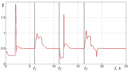
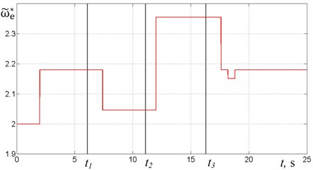
Fig. 5 shows graphs of , , for the same law of mass change (Fig. 3) but in case of using the algorithm No. 2. It can be seen (Fig. 5(b)) that when 0 resonant tuning requires one regulation step, however when tuning requires a two-step regulation.
From the presented results, it follows that both algorithms are capable of adjusting the system to the resonant mode for the given law of the mass change. The number of regulation steps required and, hence the regulation time depends on the magnitude of the mass changes. There is a difference in supply frequencies corresponding to resonant modes (Fig. 6) in case of using algorithm No. 1 and algorithm No. 2. There is also the difference in regulation accuracy: in case of using algorithm No. 2 the phase shift is almost equal to (Fig. 5(a)) whereas in case of using algorithm No. 1 deviation of from is larger (Fig. 4(a)). In the case of using algorithm No. 2, resonant tuning is generally faster and requires fewer steps than in case of using algorithm No. 1.
Fig. 5Time diagrams for algorithm No. 2
a) Phase shift
b) Supply frequency
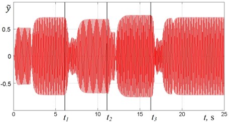
c) Platform oscillations
Fig. 6Comparison of supply frequency for algorithm No. 1 (curve 1) and algorithm No. 2 (curve 2)
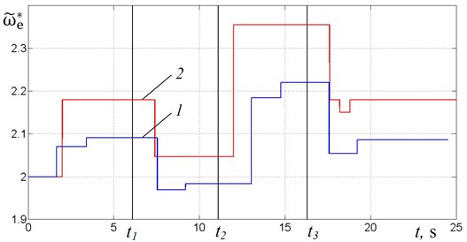
To define the boundaries of acceptable values of the mass change, the mass was changed abruptly up to a certain value . We estimated fundamental ability of the algorithms to tune the system to resonance mode, as well as the time required for this tuning depending on the ratio . It is found that in case of using algorithm No. 1, the control system provides resonant tuning if . The upper limit of this range is due to the assumed maximally permitted process load. To be noted that with increasing value the regulation time also increases. In case of using algorithm No. 2, the control system provides resonant tuning if .
5. Conclusions
As a result, it is found that both of the proposed algorithms are able to adjust the system to the resonant mode automatically in case of mass change. The algorithm based on “dynamic portrait” requires less time and less number of regulation steps for adjustment than the algorithm based on the linearized model. The estimation of ranges of the mass change demonstrates that the range is wider for the algorithm based on the linearized model. It should be also noted that the algorithm based on “dynamic portrait” requires a complex preliminary dynamics analysis, which can be only performed numerically with a pre-known parameters of the motor and exclusively for a predetermined region of possible changes in other system parameters.
Therefore, to choose control system algorithm it is necessary to consider the operating conditions of a machine, as well as the possibility and requirement of the control system re-configuration in case of machine unit replacement.
References
-
Astashev V. K., Kolovsky M. Z., Babitsky V. I. Dynamics and Control of Machines. Springer-Verlag, Berlin Heidelberg, 2000.
-
Blekhman I. I. Vibrational Mechanics. Nonlinear Dynamic Effects, General Approach, Applications. World Scientific Publishing Co., Singapore, 2000.
-
Astashev V., Babitsky V., Sokolov I. Autoresonant vibration excitation by synchronous motor. Journal of Machinery Manufacture and Reliability, Vol. 4, 1990, p. 41-46.
-
Wagg D., Neild S. Nonlinear Vibration with Control: For Flexible and Adaptive Structures. Springer International Publishing, Vol. 218, 2015.
-
Antipov V. I., Palashova I. V. Dynamics of a two-mass parametrically excited vibration machine. Journal of Machinery Manufacture and Reliability, Vol. 39, Issue 3, 2010, p. 238-243.
-
Wu A., Sun Y. Granular Dynamic Theory and Its Applications. Springer-Verlag, Berlin Heidelberg, 2008.
-
Lavendelis E. E. Vibration in the Technique: Handbook in 6 Vols. Vol. 4. Vibration Processes and Machines. Mechanical Engineering, Moscow, 1981.
-
Kononenko V. O. Oscillatory Systems with Limited Excitation. Nauka, Moscow, 1964.
-
Balthazar J. M., Cheshankov B. I., Ruschev D. T., Barbanti L., Weber H. I. Remarks on passage through resonance of a vibrating system with two degrees of freedom, excited by a non-ideal energy source. Journal of Sound and Vibration, Vol. 239, Issue 5, 2001, p. 1075-1085.
-
Felix J. L. P., Balthazar J. M., Brasil R. M. L. R. F. On Saturation control of a non-ideal vibrating portal frame foundation type shear-building. Journal of Vibration and Control, Vol. 11, 2005, p. 121-136.
-
Tomchin D. A., Fradkov A. L. Control of passage through a resonance area during the start of a two-rotor vibration machine. Journal of Machinery Manufacture and Reliability, Vol. 36, Issue 4, 2007, p. 380-385.
-
Shiriaev A. S., Fradkov A. L. Stabilization of invariant sets for nonlinear systems with applications to control of oscillations. International Journal of Robust and Nonlinear Control, Vol. 11, 2001, p. 215-240.
-
Astashev V. K., Babitsky V. I. Ultrasonic Processes and Machines. Dynamics, Control and Applications. Springer International Publishing, 2007.
-
Antipov V. Dynamics of vibrating machines with combined parametric excitation. Journal of Machinery Manufacture and Reliability, Vol. 2, 2001, p. 13-17.
-
Sobczuk D. L. Feedback linearization control of inverter fed induction motor – DSP implementation. IEEE International Symposium on Industrial Electronics, Vol. 2, 2002, p. 678-682.
-
Maaziz M. K., Boucher P., Dumur D. A new control strategy for induction motor based on nonlinear predictive control and feedback linearization. International Journal of Adaptive Control and Signal Processing, Vol. 14, 2000, p. 313-329.
-
Boukas T. K., Habetler T. G. High-performance induction motor speed control using exact feedback linearization with state and state derivative feedback. IEEE Transactions on Power Electronics. Vol. 19, 2004, p. 1022-1028.
-
Skubov D., Khodzhaev K. S. Non-Linear Electromechanics. Springer-Verlag, Berlin Heidelberg, 2008.
-
Tcheutchoua D. O., Fossi Woafo P. Dynamical behaviors of a plate activated by an induction motor. Journal of Sound and Vibration, Vol. 329, Issue 17, 2010, p. 3507-3519.
-
Holopainen T. P., Tenhunen A., Arkkio A. Electromechanical interaction in rotor dynamics of cage induction motors. Journal of Sound and Vibration, Vol. 284, Issues 3-5, 2005, p. 733-755.
-
Niselovskaya E. V., Panovko G. Ya., Shokhin A. E. Oscillations of the mechanical system, excited by unbalanced rotor of induction motor. Journal of Machinery Manufacture and Reliability, Vol. 42, Issue 6, 2013, p. 457-462.
About this article
The reported study was partially supported by RFBR, research project No. 13-08-00461_а.
