Abstract
This paper proposes one of the possible schemes of realization of the debalance for an inertial vibration exciter of a resonant vibrating machine that can automatically change the amplitude of the disturbing force by changing the eccentricity and, thus, maintain the required characteristics of the vibration process (vibration velocity, vibration acceleration, etc.) as the mass of technological load and, consequently, resonant frequency of the system changes.
1. Introduction
In modern practice, vibration machines with inertial exciters are widely used, which develop a disturbing force transmitted to the object being processed due to the rotation of an unbalanced element (debalance) with a given angular velocity [1-4]. In most cases, inertial vibration exciters with a constant static moment of a debalance are used. Usually, vibration machines with inertial vibration exciters are operated at beyond-resonance frequencies, which requires the use of vibration exciters with a significant imbalance and with a large drive power. The resonant mode of oscillations of the dynamic system of the vibrating machine can be provided by a vibration exciter with a significantly lower imbalance and, consequently, a drive with lower power, which ensures high energy efficiency of the processes. However, due to the instability of the resonant modes of operation of vibrating machines for their implementation, in particular, when the mass of technological load is changing, the control system [5-7] is used.
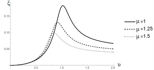
It is known that the indicators of various vibration technological processes (such as the speed of the process, machine performance, etc.) are often determined by the vibration velocity or the vibration acceleration of the working body of the vibrating machine. Despite a slight change in the natural frequency of the system (within 5-15 % of the natural frequency of the unloaded machine), caused by a change in the mass of the technological load on a vibrating machine with a constant imbalance, when it is tuned to resonance, there is a significant change in the amplitude of the working body oscillations (within 20-50 %, depending on the damping). In Fig. 1 for illustration the amplitude-frequency characteristics (AFC) curves are built for three different total mass values of the system, where indicated: ξ=A/Δlst, υ=ω/ω0, μ=(m0+mg)/m0, where A – the amplitude of resonant oscillations, Δlst=m0g/k – the static deformation of the machine’s elastic suspension with stiffness k, ω0 – the natural frequency, m0, mg – the mass of the unloaded machine and mass of technological load, g - gravity acceleration.
In this case, the vibration velocity or vibration acceleration of the working body may vary by several times. For example, when the total mass of the system is changed by 1.5 times, it can lead to a change in vibration velocity by 2.25 times, and vibration accelerations – by 2.75 times, which can significantly affect the performance indicators of the process.
In this regard, it is necessary to implement the principle of automatic variation of the disturbing force amplitude, at which the necessary amplitude of the working body oscillations is ensured in accordance with the required value of vibration velocity (or vibration acceleration) when the mass of the technological load changes. This automatic change in the amplitude of the disturbing force can be realized by changing the eccentricity of the debalance.
The authors of this paper have previously proposed the model of a self-regulating debalance of an inertial vibration exciter capable of automatically changing the amplitude of the disturbing force by changing the eccentricity, and thereby maintaining the required characteristics of the vibration process (vibration velocity, vibration acceleration, etc.) when the mass of the technological load and resonance frequency of a system change [8].
This paper describes one of possible debalance realization schemes with an automatic change in eccentricity, satisfying the conditions of constant vibration velocity or vibration acceleration of the technological process.
Fig. 1AFC of the system depending on the total mass change
2. Description and calculation of parameters of self-regulated debalance
The debalance of the exciter consists of two parts Fig. 2 (a), (b). The main part of the debalance is made in the form of a solid 1 with a cavity in which the counterweight 2 is placed, pressed against the base of the cavity by the elastic element 3. The distance from the center of mass of the main body to the axis of rotation is rd1, and the center of mass of the counterweight to the axis of rotation in the initial state is rd2. Moreover, the centers of mass of the main body and the counterweight are located opposite to the axis of rotation. The static moment of the main body (without counterweight) is set greater than the static moment of the mass of the counterweight at any of its possible displacements inside the cavity, i.e. md1rd1>md2δ, for rd2≤δ≤δmax where md1 – the mass of the main body, md2 – the mass of the counterweight, δ – the displacement of the counterweight from the axis of rotation of the debalance, δmax – the maximum constructively possible displacement of the counterweight.
Fig. 2Self-regulating debalance of inertial vibrator
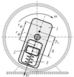
a)
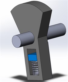
b)
During acceleration, the counterweight under the action of centrifugal force is displaced from the axis of rotation by a distance δ=δ(ω), which is determined from the equality of the centrifugal force and the restoring force F(δ) of the elastic element, i.e.: δ(ω)=F(δ)/md2ω2. The total eccentricity of such a composite debalance is rd(δ)=(md1rd1-md2δ)/md, where md=md1+md2 is the total mass of the debalance.
So the total eccentricity of the debalance increases when the frequency of rotation of the vibration exciter decreases, thereby increasing the amplitude of the disturbing force and, consequently, the amplitude of oscillations of the vibrating machine's working body and, conversely, increasing the frequency of rotation of the vibration exciter leads to decreasing the amplitude of oscillations of the working body. The force F(δ) is a previously unknown function of the counterweight displacement, and the type of this function depends on the design scheme of a particular machine and the requirements for the parameters of the generated vibration. The characteristic of the elastic element should be chosen, in particular, from the condition of constant vibration velocity (or vibration acceleration) of the vibrating machine's working body.
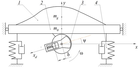
The calculation of the design parameters of such debalance proposed below is based on a simplified calculating scheme of a vibrating transport-technological machine, the oscillations of which are excited when the self-regulating debalance 3 rotates Fig. 3. The working body of the machine is a tray 2, mounted on linear elastic-viscous elements 4 of stiffness k and damping b, which, in turn, are set on a fixed base. Located on the tray, the mass of the processed material (technological load) 1 may slowly vary in time relative to the oscillation period of the platform. In this scheme, it is assumed that the tray is an absolutely rigid body and can oscillate only in the vertical direction along the y axis, which is measured from the position of the static equilibrium of the center of mass of the unloaded vibrating machine. It is also assumed that when the technological load mass changes, the resonance tuning is supported by the frequency control system with feedback on the mutual phase shift between the disturbing force and the working body oscillations [5].
Fig. 3Calculating scheme of resonance vibrating machine with the self-regulating debalance
Debalance is characterized by five main parameters: the mass of the main body of debalance md1, its eccentricity rd1, mass of counterweight md2, maximum and minimum eccentricity rd2 and δmax which are related by the following relations:
The range of variation of the total imbalance depends on the range of natural frequencies of the loaded and unloaded vibrating machine. In this paper, for definiteness, it is assumed that the range of mass variation of the entire system m∈[m0,1.3m0]. In this case, it is most often possible to isolate the nominal mass of the vibrating machine mnom=m0+0.8mgmax, on which it is required to maintain the operating frequency and amplitude of oscillations. It may be assumed that the efficiency of the technological process is ensured by the constant vibration velocity of the working body, regardless of the change in the oscillation frequency:
At the same time, to minimize the power consumption of the drive of the exciter, the debalance should have a minimum moment of inertia.
To design such a debalance, it is necessary to define a specific geometry of all the constituent elements. For definiteness, the debalance is proposed to have the form presented in Fig. 4, where two extreme positions of the counterweight are shown. This form is close to the form of debalance, usually used for the debalances with a constant value of the static moment [2].
Due to the interdependence of the geometric parameters, part of the parameters is set from strength considerations (hst, hdn, rv, hpr), and part varies (H, φ, R1, hd2, h), where h is the width of the debalance.
Fig. 4Calculating scheme of resonance vibrating machine with the self-regulating debalance
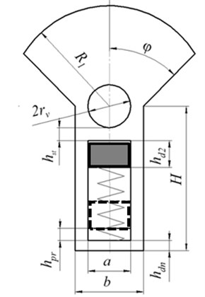
The mass characteristics are determined by the density of the debalance material, which allows, if necessary, to reduce its size when using the material with a density greater than the density of the main debalance body.
For further we will move on to dimensionless parameters by entering the following scales: m0 – mass of an unloaded vibrating machine, ω0 – natural frequency of an unloaded vibrating machine, k=ω20m0 – stiffness of an elastic suspension of a vibrating machine, Δlst=m0g/k – static deformation of the suspension of an unloaded vibrating machine, bkr=2√km0 – critical damping of an unloaded vibrating machine.
Dimensionless natural frequency of the system υ=√1/μ, where μ=m/m0 and υ=ω/ω0, moreover, for an unloaded machine υmax=υ0= 1, and for a loaded machine – υmax=√1/1,3μ. From the condition of constant vibration velocity Eq. (1), the required dimensionless amplitudes of resonant oscillations at maximum and minimum loads ξmax=υnomξnom/υmax and ξmin=υoptξopt, where ξ=A/Δlst.
The dimensionless resonant amplitude [10]: ξres=μd˜rd/˜b, where ˜b=b/bkr, μd=md/m0 and ˜rd=rd/Δlst. Dimensionless static moments of the debalance that provide resonant amplitudes of oscillations of an unloaded and loaded vibrator according to Eq. (1) have the form μd˜rdmin=ξ0˜b, μd˜rdmax=ξmax˜b/υmax.
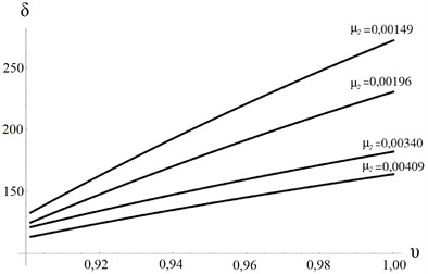
When calculating, the following debalance design parameters were determined: dimensionless displacement of the counterweight ˜δ∈[˜rd2,˜δmax] depending on the resonant frequency υ for various values of the counterweight mass μ2:
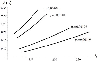
Dimensionless force characteristic of the elastic element ˜F(˜δ) of the debalance depending on the displacement ˜δ at various values of the mass of the counterweight μ2:
By specifying three parameters, for example ˜R1, φ and ˜H, and using the parameter search with a certain step, the corresponding parameters ˜h and ˜hd2 can be obtained and an array of geometrically possible debalance realizations that provide the desired change in the static moment. For each option, the dimensionless mass of the main body and the counterweight, the total mass and the total minimum and maximum eccentricity, the minimum and maximum inertia of the debalance are determined. Among these options, in accordance with the specific conditions (for example, the minimum moment of inertia), the feasible option is chosen.
Further, the process is iterative in nature – a verification strength analysis is carried out, the structural dimensions are reduced (increased) and the variable sizes are recalculated in order to achieve an optimal result.
Fig. 5 shows the graphs of the displacement of the counterweight depending on the natural frequency Fig. 5(a) and the mass of the counterweight and the power characteristics of the elastic element Fig. 5(b). The main feature of the obtained graphs is almost a linear characteristic of the rigidity of the elastic element of the debalance.
Fig. 5Dependencies: a) displacement of the counterweight depending on the natural frequency, b) the power characteristics of the elastic element depending on the mass of the counterweight
a)
b)
3. Conclusions
Summing up, it can be concluded that the proposed design of self-regulating debalance makes it possible to maintain the required vibration velocity of the working body of a resonant vibrating machine, regardless of the change in the mass of the process load.
References
-
Gutman I. Industrial Uses of Mechanical Vibrations. Business Books Limited, London, 1968.
-
Vibration in Engineering: Handbook. Vol. 4, Mechanical Engineering, Moscow 1981.
-
Bykhovsky I. Fundamentals of the Theory of Vibration Technology. Mechanical Engineering, Moscowl, 1968.
-
Goncharevich I., Frolov K. Theory of Vibration Technique and Technology. Science, Moscow, 1981.
-
Panovko G., Shokhin A., Eremeikin S. The control of the resonant mode of a vibrating machine that is driven by an asynchronous electro motor. Journal of Machinery Manufacture and Reliability, Vol. 44, Issue 2, 201, p. 109-113.
-
Panovko G., Shokhin A., Eremeykin S., Gorbunov A. Comparative analysis of two control algorithms of resonant oscillations of the vibration machine driven by an asynchronous ac motor. Journal of Vibroengineering, Vol. 17, Issue 4, 2015, p. 1903-1911.
-
Afanasiev A., Potapov V., Suslov D., Chirkova A. Twomasses resonant clatter with linear controlled engine. Transbaikal State Univercity Journal, Vol. 23, Issue 8, 2017, p. 19-24.
-
Krestnikovski K., Panovko G., Shohin A. Determination of elastic characteristics of self-regulating debalance for inertial exciter. Journal of Machine Construction and Engineer's Education, Vol. 4, 2018, p. 20-25.
Cited by
About this article
The research was supported by Russian Science Foundation (Project No. 18-19-00708).

