Abstract
Dynamic visual cryptography scheme based on time-averaged fringes generated by Ronchi-type geometric moiré gratings on finite element grids is proposed in this paper. A single cover image is used to encode the secret image and is formed on the surface of a deformable structure. Time-averaged moiré fringes leak the secret when the structure is oscillated according to a predefined Eigen-shape. The envelope functions determining the motion induced blur of the Ronchi-type moiré grating depend on the characteristic features of the motion. And though harmonic oscillations do not result into a completely uniform time-averaged image of the Ronchi-moiré grating, initial phase scrambling and phase normalization algorithms are used to encode the secret in the cover image. Theoretical relationships between the amplitude of the Eigen-shape, the order of the not completely developed time-averaged fringe and the pitch of the deformable one-dimensional Ronchi-type moiré grating are derived.
1. Introduction
Visual cryptography (VC) is a cryptographic technique which allows visual information (pictures, text, etc.) to be encrypted in such a way that the decryption can be performed by the human visual system, without the aid of computers. VC was pioneered by Naor and Shamir in 1994 [1]. They demonstrated a visual secret sharing scheme, where an image was broken up into a number of shares so that only someone with all shares could decrypt the image. Each share was printed on a separate transparency, and decryption was performed by overlaying the shares. When all shares were overlaid, the original image would appear. Since 1994, many advances in visual cryptography have been made. Visual cryptography for color images has been proposed in [2, 3]. Ideal contrast visual cryptography schemes have been introduced in [4]. A general multi-secret visual cryptography scheme is presented in [5]; incrementing visual cryptography is described in [6]. A new cheating prevention visual cryptography scheme is discussed in [7].
An image hiding technique, when the secret image leaks in a form of a time-averaged moiré fringe in an oscillating non-deformable cover image, was first presented in [8]. A stochastic moiré grating is used to embed the secret into a single cover image, and the secret can be visually decoded by the naked eye only when the amplitude of the harmonic oscillations corresponds to an accurately preselected value. The fact that the naked eye cannot interpret the secret from a static cover image makes this image hiding technique similar to VC. Special computational algorithms are required to encode the image, but the decoding is completely visual. The difference from VC is that only a single cover image is used and that it should be oscillated in order to leak the secret. Some additional security measures are implemented as described in [9], where the secret is leaked only when pattern, containing secret information, is oscillated according to a predefined law of motion.
An alternative image hiding scheme is based on deformable moiré gratings, where secret image is leaked from the cover image not when it is oscillated according to a pre-determined law of motion – but when it is deformed along the longitudinal coordinate of the stochastic moiré grating. Such implementation requires a special strategy for the formation of the cover image and opens new possibilities for optical control of vibrating structures. A natural extension of such image hiding technique would be a dynamic visual cryptography (DVC) scheme based on harmonic oscillations of the deformable moiré grating according to a pre-selected Eigen-shape of an elastic structure [10]. However, the formation of a moiré grating with a harmonic variation of grayscale levels on a surface of a deformable structure remains a challenging technological problem, especially if micro-electro-mechanical systems (MEMS) are considered. Thus, the main objective of this manuscript is to construct the algorithms for the formation of cover images based on Ronchi-type moiré grating for such demanding applications.
For the time-averaged fringes to form correctly using Ronchi-type moiré grating, triangular waveform oscillation function is required. The triangular waveform vibrations are often found in practical applications, such as investigating multilayered structures or image processing. Zig-zag scan hysteresis is found after image compression, which, in case of insufficient number of bits’ available, results in macro blocking. Zig-zag scan hysteresis also appears in nano-systems, when using near-field scanning optical microscopes [11]. A layer wise zig-zag model for the vibratory response of soft-cored nonsymmetrical sandwich beams is proposed in [12]. Zig-zag effect is used to perfectly bond together adjacent layers of laminate [13]. Thus, it is natural to adapt zig-zag/triangular waveform in DVC.
This paper is organized as follows. Optical background of the problem is discussed in section 2; the construction of a deformable moiré grating is presented in section 3; the DVC scheme based on deformable gratings is illustrated in section 4; concluding remarks are given in section 5.
2. Optical relationships
Let us consider two different one-dimensional geometrical moiré gratings – a harmonic moiré grating:
and a Ronchi-type moiré grating:
where x is the longitudinal coordinate; λ is the pitch of the grating; the numerical value 0 corresponds to the black color; 1 – to the white color.
Firstly, let us assume that these gratings are formed on a surface of non-deformable structure which does oscillate around the state of equilibrium according harmonic law of motion:
where a is the amplitude of oscillations, ω is the angular frequency and fi is the phase of harmonic oscillations. Moiré gratings are blurred due to these oscillations; the motion induced blur in the time-averaged image reads [8]:
where T is the exposure time and J0 is the zero order Bessel function of the first kind. The decay of the contrast of the time-averaged harmonic moiré grating at increasing amplitudes of harmonic oscillation is non-monotonous. Time-averaged moiré fringes are formed at such amplitudes which correspond to the roots of J0:
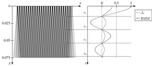
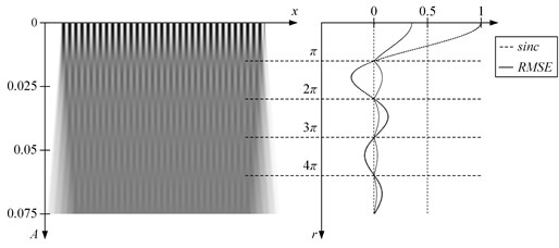
where rk is the k-th root of J0. However, the relationship (4) does not hold for the Ronchi-type moiré grating – time-averaged fringes do not form at any amplitude of harmonic oscillations [9] (Fig. 1). Ronchi-type moiré gratings generate time-averaged fringes only if the waveform of the oscillation is triangular [9] – this phenomenon could be exploited as an additional factor of encoding security in DVC applications.
Fig. 1Oscillation of the inelastic one-dimensional moiré grating (λ=0.03) produces time-averaged fringes. Time averaged image is shown on the left; the RMSE errors from the equilibrium and graph of sinc or Bessel function – at the right part of the figure. Time-averaged fringes do form correctly if harmonic cover image is oscillated according harmonic law (a). If image is oscillated according triangular wave-form function (b), fringes does also form, but at sinc function’s roots
a)
b)
To prove and adapt this phenomenon on dynamic visual cryptography it could be split into two parts. Firstly, provided idea can be simplified by using harmonic moiré grating instead of Ronchi-type moiré grating, oscillated according triangular wave-form function. If amplitudes, where time-averaged moiré fringes forms, could be verified on the simplified version, hypothesis that Ronchi-type moiré grating also forms at the same amplitudes could be proved experimentally.
Thus, a cover image formed on a surface of a deformable structure would not oscillate according to the law described in (3). Let’s define triangular wave-form function used in oscillations with period 2π and value range from -1 to 1:
Let the deformation from the state of equilibrium at the point x at time moment t be equal to u(x,t). Then the explicit deformation of the moiré grating reads:
if only x can be explicitly expressed from the equality:
in the following form:
Let us describe an oscillation around the state of equilibrium with function u(x,t):
It is the simple form of triangular wave-form function, where a(x) is the Eigenshape of in-plane oscillations and time t∈[-1,1]. The field of amplitudes a(x) can be linearized around the point x0:
where a0=a(x0); ˙a0=da(x)dx|x=x0. Then equalities 8, 9 and 10 yield:
Finally, the grayscale level of the moiré grating at coordinate x and time moment t reads:
2.1. Non-deformable moiré grating
Let us assume that a(x)=A (A is a constant) and oscillations are done using triangular wave-form function. This means that the deflection, which describes the oscillation of a non-deformable body around the state of equilibrium, equals u(x,t)=At [8]. Then the grayscale level of the moiré grating at time step t reads:
Time-averaging techniques can be used to register the image of the grating [8, 14]:
where sinc(x)=sin(x)x is cardinal sine function. Note that the distribution of the grayscale level in the time-averaged image does not depend on characteristics of triangular wave-form function (9) and this is why the simple form could be used in provided calculations.
Gray time-averaged moiré fringes do form when sinc(x)=0 – what happens at amplitudes 2πλAk=rk (rk=πk are roots of sinc(x); k=1,2,…) and are illustrated in Fig. 1(b).
2.2. Deformable moiré grating; linear deformation field
Next assume that a(x)=Ax. The principal difference from non-deformable moiré gratings (described in Section 2.1), is that the moiré grating will deform proportionally to the coordinate x, when the body is oscillated in time. However, harmonic moiré grating can still be formed on the surface of the one-dimensional body in the state of equilibrium.
Linearization around x0 yields: a(x)=Ax0+A(x-x0); a0=Ax0; ˙a0=A. Thus, Eq. (12) now reads:
Note that a singularity occurs at A=1 in Eq. (15). Thus, it is assumed that 0<A≪1. Finally, the time-averaged image reads:
Fig. 2Deformable one-dimensional moiré grating produces time-averaged fringes when oscillated according to the triangular wave-form. One period (t∈-1, 1) of oscillations is shown in the top left image; one-dimensional time-averaged image at A*=0.05 is shown at the bottom on the left; the formation of time-averaged fringes then different amplitudes is illustrated on the right; A=0.001, 0.1-
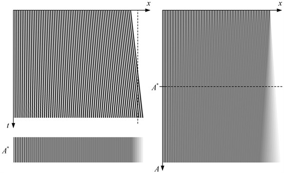
In this case, time-averaged moiré fringes form at 2πλAx=rk=πk; k=1,2,…. Figure 2 shows the oscillating moiré grating in the left upper image. The one-dimensional moiré grating is motionlessly fixed on the left side and the right side of the grating deforms at an amplitude A*=0.05. The vertical dashed line marks the equilibrium state of the one-dimensional deformable structure; the pitch of the moiré grating is λ=0.015. The right part of Fig. 2 shows the time-averaged images of the one-dimensional moiré grating at different amplitudes A. The left bottom part of Fig. 2 illustrates time-averaged moiré fringes at A*=0.05.
2.3. Deformable moiré grating; nonlinear deformation field
The main objective of this paper is to develop an image hiding scheme based on deformable moiré gratings on finite element grids under the assumption that the deformation field a(x) is a nonlinear function. Without losing the generality we set x0=0. Let us denote ˉa(x)=a0+˙a0x. Now, Eq. (12) reads:
If ˙a0≪1 and t2≤1 then a0˙a0t2≪1 and:
Note that ∫1-1sin(2πλˉa(x)t)dt=0 due to the evenness of the sine function. Then, the time-averaged image reads:
Thus, time averaged moiré fringes form at 2πλˉa(x)=rk=πk; k=1,2,…, which corresponds well to the results produced in Sections 2.1 and 2.2. The goal is to transform the whole image into a time-averaged moiré fringe (only by varying the pitch λ(x)). Thus, the distribution of the pitch reads:
In previous relationship λ still depends on the linearized field of amplitudes ˉa(x). The conjecture that ˉa(x) can be replaced with a(x) will be tested and validated by using computational tools. Let us assume that a one-dimensional elastic structure oscillates according to the following law:
The above stated presumption implies that a time-averaged moiré fringe must form in the whole domain of x when the stationary moiré grating has the variable pitch in respect of x:
The parameter k is fixed to 1, because the contrast around the first time-averaged moiré fringe is the highest (the first root of sincr1=π). Now, instead of applying the oscillations of the moiré grating according to Eq. (21) we set the oscillation process to:
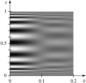
where the parameter b is varied from 0 to 0.2 (Fig. 3). It can be clearly seen that the time-averaged moiré fringe does form at b=0.1. Thus, the conjecture stating that that the linearized field ˉa(x) can be replaced by a(x) in Eq. (20) does hold.
Fig. 3Time-averaged image of the one-dimensional grating (the variation of the pitch is determined according to Eq. (22)); the variation of the amplitude b is determined by Eq. (23)
3. Ronchi-type moiré gratings on finite element grids
The main objective of this paper is to develop an image hiding scheme based on deformable Ronchi-type moiré gratings on finite element grids. In other words, cover image should only have two colors black or white. In section 2 it was proved, that time-averaged fringes forms then harmonic moiré grating is oscillated according triangular wave-form function. This raises a hypothesis that the same should hold true with Ronchi-type moiré gratings Eq. (2).
Fig. 4Time-averaged fringes do form correctly if Ronchi-type moiré grating is oscillated according triangular wave-form function. Fringes form, at sinc function’s roots rk=πk
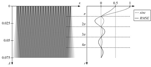
Hypothesis can be confirmed experimentally the same way as with harmonic moiré gratings. From Fig. 4 it can be seen that time averaged fringes do form correctly at rk=πk if Ronchi-type moiré grating is oscillated according triangular wave-form function.
4. Dynamic visual cryptography based on deformable moiré gratings on Finite Element grids
The time-averaged moiré fringes will be formed using previously mentioned nonlinear deformation fields. This process does results only in 1D moiré gratings, thus to extend it to 2D model, the field of deformations should be sliced horizontally (or vertically). The deformation field must be determined by FEM computations. This process is illustrated in Fig. 5.
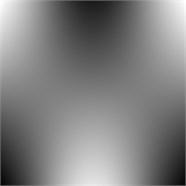
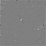
The 2D deformation field is shown in Fig. 5(a), there the 10-th Eigen-shape of a plate is selected. White zones stand for no oscillation and dark zones for maximum deformations from the equilibrium. The resolution of Fig. 5(a) is 500×500 pixels, so all further calculations are related to this size. Because, provided model forms only one-dimensional time-averaged moiré, an array of 500 one-dimensional moiré gratings must be formed and concatenated vertically. This results in 2D stationary moiré grating shown in Fig. 5(b). Grating pitch is constructed using Eq. (22), there the linearized deformation field ˉa(x) is replaced by ka(x)+b. This transformation of the numerical values of the Eigen-shapes a(x) is necessary in order to avoid singularities at the points where the amplitudes a(x) become equal to 0. k, b are positive constants greater than 0, and all further computations is set to k=0.0045 and b=0.0055. Thus, if the initial range of the Eigen-mode is [-1,1], after this transformation the working range of amplitudes becomes [0.001,0.01].
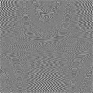
Now, we must note that initial phase of all 500 horizontal 1D gratings is the same and equals to 0. This results in clean pattern and especially – interpretable Eigen-shape function. To avoid this the stochastic initial phase scrambling algorithm [8] should be used to complicate the pattern (Fig. 5(c)) (during this process the pitch in every single one-dimensional grating is not altered).
After this preparation, every one-dimensional grating is time-averaged according to the x-axis, using triangular function. These in-plane unidirectional oscillations result in completely gray image (except the left and right boundaries where the image becomes slightly uneven) shown in Fig. 5(d).
Fig. 5Triangular wave-form oscillations according to the 10-th Eigen-mode of a Ronchi-type moiré, produce a gray two-dimensional image; part (a) shows the Eigen-shape; part (b) illustrates the stationary moiré grating (the pitch of the grating varies in the interval λ=0.002, 0.02; λ(x)=2a(x); part (c) shows the cover image produced from the moiré grating; part (d) illustrates the time-averaged image when the cover image is oscillated according the 10-th Eigen-mode
a)
b)
c)
d)
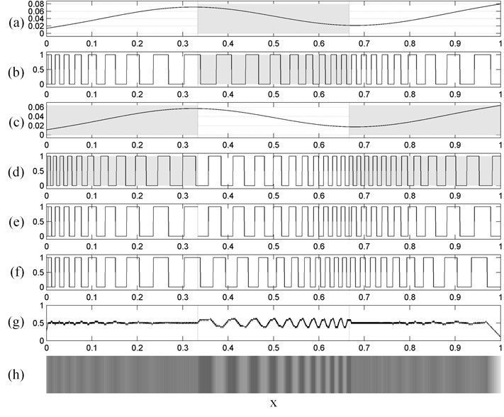
We have experimentally proved that Ronchi-type moiré, when oscillated according to triangular wave-form function, as well works with nonlinear amplitude functions. The last step is to encode secret image into the cover image, which is done by modifying the phase regularization algorithm introduced in [8] (Fig. 6). The variation of the amplitude a(x) is depicted in Fig. 6(a). The corresponding grayscale level of the one-dimensional moiré grating is illustrated in Fig. 6(b). Let us place the block of “secret” information in the middle of the grating, meaning that time-averaged moiré fringe should form everywhere, except in the middle.
Now, the white zones (the left and right-third of Fig. 5(b) and the middle-third of Fig. 5(d)) are taken into the composite grating illustrated in Fig. 6(e). Direct copying results into a non-continuous grating with phase jumps at the joining points, which are eliminated with phase-regulation algorithm (Fig. 6(f)). Note that the variation of the pitch is not altered in this process. Lastly, time-averaging of Fig. 6(f) results into Fig. 6(g) as it is oscillated by the law defined by Eq. (8) and the field of amplitudes a(x) is determined by Fig. 6(a). Time-averaged moiré fringes do form in the middle-third of the time-averaged image; the left-third and the right-third of the image does clearly stand out from the gray background.
Fig. 6A schematic diagram illustrating the encoding of the secret in a one-dimensional moiré grating. Part (a) shows the field of amplitudes a(x); part (b) illustrates the corresponding moiré grating. Part (c) shows the field of amplitudes used in the regions occupied by the secret; part (d) illustrates the corresponding moiré grating. The composite moiré grating uses the left and the right thirds from part (b) and the middle third from part (d). All discontinuities in part (e) are eliminated by the phase regularization algorithm (part(f)). The time-averaged image of (f) is shown in parts (g, h).
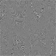
Provided image hiding scheme effective embeds dichotomous images into the cover images. To assure the functionality of such image hiding scheme based on dynamic visual cryptography, lets embed secret dichotomous image Fig. 7(a) into the cover image Fig. 7(b). The cover image generated according to the 12-th Eigen-mode, where initial phase is stochastic in all horizontal one-dimensional gratings and phase regularization algorithms are used to hide the secret. The encoding result is uninterpretable to naked eyes.
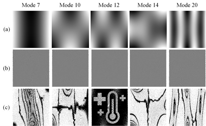
Moreover, decoding process dependency on the initial Eigen-shape of the structure, introduces one more security feature: secret information is inaccessible without using correct Eigen-shape to oscillate the cover image. Thus, the Eigen-mode itself can be considered as a key for the visual decoding procedure. Such dependence is shown in Fig. 8 where visual decoding is executed using different Eigen-modes. The contrast enhancement procedures [15] are used to highlight moiré fringes in time-averaged images.
Fig. 7The secret image is shown in part (a); the cover image with the embedded secret according to the 12-th Eigen-mode is shown in part (b).

a)
b)
Fig. 8The Eigen-mode serves as the key for visual decryption of the cover image. The first row shows different Eigen-shapes; the row column – time-averaged images; the third row – contrast enhanced time-averaged images
5. Conclusions
Dynamic visual cryptography scheme based on Rochi gratings and triangular waveforms is presented in this paper. An image encoding scheme in deformable one-dimensional moiré gratings oscillating according to a predefined Eigen-mode is developed and implemented for the construction of two-dimensional digital dichotomous secret images. The secret is leaked from the cover image when it is oscillated according to a predefined Eigen-mode. The efficiency of the proposed scheme is illustrated by computational examples.
References
-
Naor M., Shamir A. Visual cryptography. Advances in Cryptology, Eurocrypt ’94 Proceeding, Springer, 1995, p. 1-12.
-
Luo Hao, Chen Hua, Shang Yongheng, Zhao Zhenfei, Zhang Yanhua Color transfer in visual cryptography. Measurement, Vol. 51, 2014, p. 81-90.
-
Yang Ching-Nung, Chen Tse-Shih Colored visual cryptography scheme based on additive color mixing. Pattern Recognition, Vol. 41, Issue 10, 2008, p. 3114-3129.
-
D’Arco P., De Prisco R., De Santis A. Measure-independent characterization of contrast optimal visual cryptography schemes. Journal of Systems and Software, Vol. 95, 2014, p. 89-99.
-
Shyu Shyong Jian, Huang Shih-Yu, Lee Yeuan-Kuen, Wang Ran-Zan, Chen Kun Sharing multiple secrets in visual cryptography. Pattern Recognition, Vol. 40, Issue 12, 2007, p. 3633-3651.
-
Gupta Ankit, Saxena Kshitiz Region incrementing visual cryptography. International Conference on Medical Imaging, m-Health and Emerging Communication Systems, 2014, p. 247-250.
-
Pei-Yu Lina, Ran-Zan Wanga, Yu-Jie Changc, Wen-Pinn Fangd Prevention of cheating in visual cryptography by using coherent patterns. Information Sciences, Vol. 301, Issue 20, 2015, p. 61-74.
-
Ragulskis M., Aleksa A. Image hiding based on time-averaging moiré. Optics Communications, Vol. 282, Issue 14, 2009, p. 2752-2759.
-
Ragulskis M., Aleksa A., Navickas Z. Image hiding based on time-averaged fringes produced by non-harmonic oscillations. Journal of Optics A: Pure and Applied Optics, Vol. 11, Issue 12, 2009, p. 125411.
-
Vaidelys M., Ragulskiene J., Aleksiene S., Ragulskis M. Image hiding in time-averaged moiré gratings on finite element grids. Applied Mathematical Modelling, Vol. 39, Issue 19, 2015, p. 5783-5790.
-
Seibel E. J., Pollack G. H. Imaging ‘intact’ myofibrils with a near field scanning optical microscope. Journal of Microscopy, Vol. 186, Issue 3, 1997, p. 221-231.
-
Xavier Pascal B., Chew C. H., Lee K. H. An improved zig-zag model for the vibration of soft-cored unsymmetric sandwich beams. Composites Engineering, Vol. 4, Issue 5, 1994, p. 549-564.
-
Ferreira A. J. M., Roque C. M. C., Carrera E., Cinefra M., Polit O. Two higher order zig-zag theories for the accurate analysis of bending, vibration and buckling response of laminated plates by radial basis functions collocation and a unified formulation. Journal of Composite Materials, Vol. 45, Issue 24, 2011, p. 2523-2536.
-
Kobayashi A. Handbook on Experimental Mechanics. 2nd ed., Bethel, SEM, 1993.
-
Ragulskis M., Aleksa A., Maskeliunas R. Contrast enhancement of time-averaged fringes based on moving average mapping functions. Optics and Lasers in Engineering, Vol. 47, Issues 7-8, 2009, p. 768-773.
