Abstract
Heave compensator attenuate vessel heave motion during drilling operation of drillship. Heave compensator functions as damping form motion of drillship, such as principle spring of suspension system. The load transfers on the parts of heave compensator. Stress and deformation of all parts is evaluated to diagnose the stability of the compensator. This study makes a decision on the safety of structure. Results of analysis confirm the structure stability of heave compensator for simulation. This result can be used as data for structural analysis to determine safety of a structure.
1. Introduction
1.1. Outline
The compensator located on the upper part of the derrick for compensation of heave motion of wave applied during a drilling work is a compensation device which uses an oil pressure cylinder, and is affected by the load of the drill string and the load from the external environment. Accordingly, it is important to determine safety of structure considering various loads. This system is consist of drill string compensator(DSC) and active heave compensator, put the oil and air pressure control to use. Drill string compensator serves to reduce the disturbance to 90 % for the external environment. The Active Heave Compensator is designed to be added to the Drill String Compensator to play the role of reducing disturbance of heave motion by about 5 % and to apply control force to the part supporting the heavy object, and can attenuate disturbance of heave motion by applying control force in positive or negative direction. An oil pressure system is used in general to apply the control force. Various motion control devices are used to compensate for the vertical motion of the vessel.
J. T. Hatleskog researched compensation system by the 5 body (platform, crown block, traveling block, upper drill string and lower drill string). The input data of platform’s behavior is period [1, 2]. But, in this study, the safety of the structure was not determining. Nam-Kug Ku researched dynamic behavior of vessel’s hosting system in order to analyze dynamic behavior of multi-body dynamics system using developed kernel [3]. This study conducted dynamic analysis about heave compensation system. In addition, this studied load of drill string depending on compensation system following system mechanism. But, Safety of compensator structure having external loads is not studied. K. D. Do examined the operation of the drilling system using mathematical model [4]. But, in this research, the stress state of the structure was not identifying. Therefore, this study confirms influence of AHC-cylinder and DSC-cylinder to identify the safety compensator structure of heave compensator. Heave compensator is modeled by the finite element. The stress distribution and safety was judged to the working compensator.
1.2. Wave load
Unlike the case of the ground, the drillship operating on offshore drilling is influenced by live load, dead load and environmental load. Therefore, Environmental load considers wave height of target area influence. Once analysis, ocean waves are irregular and random in shape, height, length and speed of propagation. Regular travelling wave is propagating with permanent form. It has a distinct wave length, wave period and wave height. Therefore, analysis has to take them into consideration.
Fig. 1Six degrees of freedom of vessel
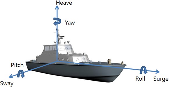
Analysis of ocean floating structure is import to take six degrees of freedom (surge, sway, heave, roll, pitch and yaw) into consideration. Fig. 1 shows the six degrees of freedom of vessel. For a floating structure the vertical displacement of the structure can be written as:
where z is vertical displacement of platform, and it is meant value that the different coordinates add up. because it is affected on rolling, pitching and heaving motion. ζ3(t) is heave translational motion, ζ4(t) is roll rotational motion, ζ5(t) is pitch rotational motion.
The stress distribution the topside structure is governed by the structural design of the topside, local loads and ship accelerations and deformation. The total design force for topside/deck equipment is calculated as follow:
where Fv is force on the structure due to gravity and vertical acceleration, Ft is force on the structure due to transverse acceleration, Fl is force on the structure due to longitudinal acceleration, γs is load factor for static loads, γw is environmental load factor, g is acceleration of gravity (9.81m/s2), av is vertical acceleration at the relevant C.O.G. calculated by hydrodynamic analysis with annual probability of exceedance, at is transverse acceleration calculated at the relevant C.O.G. by hydrodynamic analysis, θ is roll angle of ship, al is longitudinal acceleration at the relevant C.O.G. by hydrodynamic analysis, Φ is pitch angle, m is mass of the structure/equipment [5].
Roll, pitch and heave in the equations above are deducted by value for acceleration. When value of roll and pitch are 13 degrees and 8 degree, av, at and al are 3.6 m/s2, 6.4 m/s2 and 4.5 m/s2, respectively.
1.3. Multi-body dynamics
Development of the product is necessary that achieve the desired performance, the vibration analysis, a structure stress evaluation, a noise characteristics of fatigue life prediction in pursuance stability of the structure and vibration characteristics. Recently, Trend of mechanical structure is high speed and light weight ranging from high-precision machine to large machine. Performance of mechanical structure depends on static stiffness, dynamic stiffness and thermal characteristic. Behavior analysis of structure on dynamic load part is becoming more and more important [6-9].
Multi-body dynamic is based on Lagrange Equation. Which is the calculation of motion and position, speed and acceleration through time-integrating, also reaction force is calculated in the joint. Therefore, it judges behavior of parts according to load and deformation, the design error between parts can be checked.
The multi-body dynamics solution from ANSYS offers extensive versatility in handling the degree of required complexity. Multi-body dynamics from ANSYS Workbench supports two methods. One is rigid dynamics the other is flexible multi-body dynamic. Multi-body dynamics analysis is used on joint to connect parts. Multi-body dynamics simulates motions and forces of parts interconnected to one another via sets of constraints modeled as joints.
2. Simulation
2.1. Heave compensator modeling
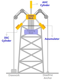
The 3D model of the heave compensator was made using CATIA v5. Fig. 2 is the shape of 3D model using CATIA. 3D model composed with crown block as the center, frame connect derrick is fixed position of crown block. AHC-cylinder is on the crown block, Slanted DSC-Cylinder 4 sets are under crown block. The locker-arm is located flank the crown block. Fig. 3 shows the arrangement of heave compensator. In this research, dynamic analysis of the heave compensator apply to the flexible body. First, heave compensator is modeled by the finite element. And, the stiffness and damping of the cylinder was applied to a kinetic model. Second, Environmental loads used in the analysis were applied to the wave loads in sea. Third, the stress distribution and safety examined heave compensator.
Fig. 2Heave compensator 3D model from CATIA
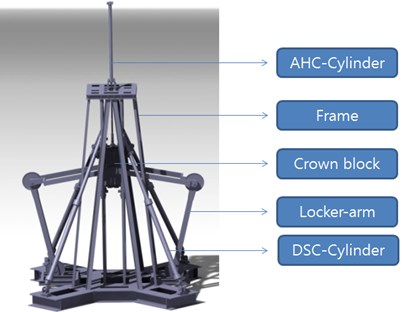
Fig. 3Compensator arrangement
2.2. Boundary conditions
Fig. 4 shows the joint condition of multi-body dynamics analysis from ANSYS program. This joint select between the connection to the parts necessary for the analysis. Interconnection of parts via joints is greatly simplified by considering the finite motion at the two nodes forming the joint element. Revolute joint is a two-node element that has only on primary degree of freedom, the relative rotation about the revolute axis. Translational joint element is a two-node element that has on relative displacement degree of freedom. Cylindrical joint element is a two-node element that has on free relative displacement degree freedom and one free relative rotational degree of freedom (around the cylindrical or revolute axis). Conditions appropriate for each part of the joint was applied as follows:
A. Revolute condition was applied on pin for connection of each parts.
B. Translational condition was applied on between Frame and crown block.
C. Cylindrical condition was applied on DSC-Cylinder and AHC-Cylinder.
D. Fixed support was applied while there is no movement between each part.
E. DSC-Cylinder is applied a spring condition for damping role.
Fig. 4Boundary conditions of ANSYS
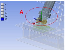
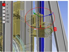
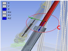
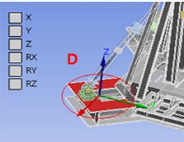
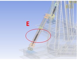
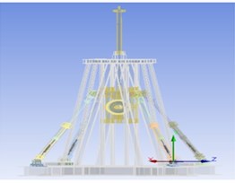
Fig. 5Mesh of compensator model
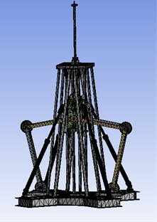
Mesh is generated for finite-element analysis. Cylinder is applied to the hex-dominant. The other parts are applied to the tetrahedrons. Nodes number are 402,841 and elements number are 216,595. The size of mesh is 50 mm to 100 mm. Mesh number is a sufficient to indicate the stress distribution. Therefore, compensator is big and complex. Fig. 5 shows the finite-element analysis.
The material used in finite-element analysis is DH36 structural steel. Thick plate of DH36 with high strength is applied as material in the finite-element analysis. Table 1 shows material property of DH36. The yield strength of the DH36 steel agrees with the requirement of DNV. In addition, while comparing the yield strength in ASTM with DNV, DNV is superior to ASTM.
Table 1Material properties of DH 36
ASTM A131 steel, DH 36 | |
Density | 7850 kg/m |
Yield strength | 350 MPa |
Ultimate strength | 490-630 MPa |
Young’s modulus | 216 GPa |
Poisson’s ratio | 0.26 |
2.3. Load condition
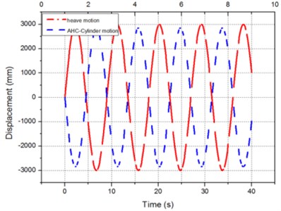
Sheave of crown block is applied 1040 ton of live load (standard is drill depth the 10000 m class). Heave motion is applied wave period (height 6 m, period 9 s) of target area to control of AHC-Cylinder. Acceleration is applied consider rolling, Pitching and heaving. Fig. 6 shows the load condition of Heave compensator. A live load of 908 ton was applied to the sheave of the crown block, and its own weight was taken into account. Fig. 7 shows the motion of AHC-Cylinder motion and heave motion.
A sine wave with 3,000 mm amplitude and 9 second cycle was applied to the frame connected to the derrick to take into account the flow of the external fluid (heave motion) transferred to the hull, and a sine wave with 2,850 mm amplitude and 9 second cycle was applied in reverse waveform to take into account the control force of the AHC cylinder over such heave motion.
Fig. 6Load condition of analysis for heave compensator
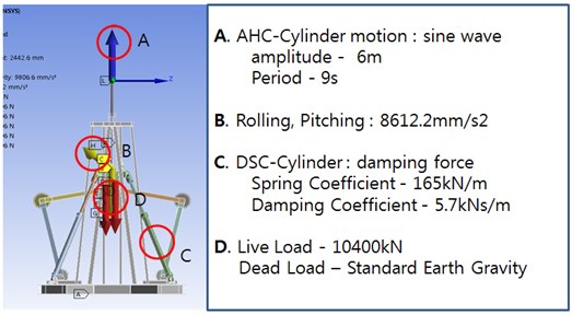
Fig. 7Motion of heave and AHC cylinder
3. Results
Fig. 8 shows the result of equivalent stress analysis. Maximum stress generate on the rod of AHC-Cylinder connect crown block. Where, Maximum stress value is 181.22 MPa. AHC-Cylinder rod stress value is 147.82 MPa, DSC-Cylinder rod stress value is 114.64 MPa. The rod of AHC-cylinder is show the maximum value. Because, AHC-cylinder lifts the loads, it acts as the rise of the crown block. Stress value of crown block top part and frame bottom part is 50-70 MPa. Safety factor means allowable stress/von-mises stress. This is using the von-mises method of finite element analysis. Safety factor of structure is 1.8.
This analysis is further applied to the motion of AHC-Cylinder. Stress concentration is generated on the rod of AHC-Cylinder and DSC-Cylinder influence of the live load and motion of the parts. This position is AHC-Cylinder rod. Fig. 9 shows result of equivalent elastic strain. Maximum value of equivalent elastic strain is 0.001122 mm. This position is AHC-Cylinder rod.
Fig. 8Results of analysis of equivalent stress
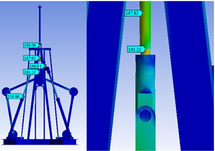
Fig. 9Results of analysis of equivalent elastic strain
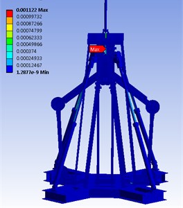
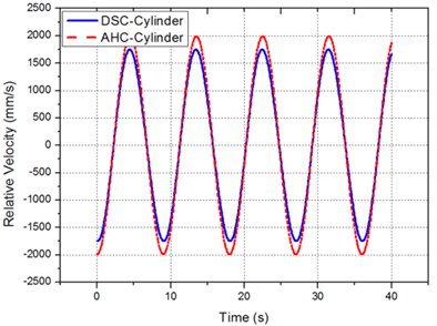
Fig. 10 shows the result of displacements from the initial locations of the crown block and the frame obtained through MBD analysis. Fig. 11 shows the speeds of the DSC cylinder and the AHC cylinder by time band. When the compensation rate for heave movement of ±3,000 mm was 95 %, the maximum speeds of the DSC cylinder and the AHC cylinder were 1.750 m/s and 1.989 m/s respectively. This result can be used as data for structural analysis to determine safety of a structure.
Fig. 10Position of crown block and frame
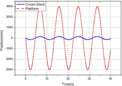
Fig. 11Velocity of AHC and DSC cylinder
4. Conclusions
This study is structure analysis of true size assembly for technical development of heave compensator. Safety assessment of structure is simulation of true environment by multi-body dynamics of ANSYS.
1) Result of simulation is high stress concentration to AHC-Cylinder rod. But, Safety coefficient consequential stress distribution of structure is 1.8. Standard of a design is DNV rules. It standard safety coefficient is 1.2-1.3. Therefore, Heave compensator is safe taking DNV rule into consideration. Result of this study is only considers wave condition. Thus, safety decision of structure is to consider additional external load.
2) The speeds of the AHC cylinder and the DSC cylinder were confirmed through MOD analysis when the attenuation is 95 %. The design speed of the 1/5 size cylinder model is 1.5 m/s. The AHC cylinder speed of 1.989 m/s and the DSC cylinder speed of 1.750 m/s obtained through a dynamics analysis are confirmed, and can be utilized for design of an actual size cylinder.
References
-
Hatleskog J. T., Dummigan M. W. Passive compensator load variation for deep water contact operation. Conference of OCEANS, 2006, p. 18-21.
-
Hatleskog J. T., Dummigan M. W. Peer-reviewed technical communication-passive compensator load variation for deep-water drilling. IEEE Journal of Oceanic Engineering, Vol. 32, Issue 3, 2007, p. 593-602.
-
Ku N. K., Ha S., Roh M. I. Study on the applicability of a new multi-body dynamics program though the application to the heave compensation system. Journal of the Computational Structural Engineering Institute of Korea, Vol. 26, 2013, p. 247-254.
-
Do K. D., Pan J. Nonlinear control of an active heave compensation system. Ocean Engineering, Vol. 35, 2008, p. 558-571.
-
DNV Offshore Standards. DNV-RP-C102, Appendix B, 2002.
-
Jang J. S., Sohn J. H. Dynamic analysis of wave energy generation system by using multibody dynamics. The Korean Society of Mechanical Engineers, Vol. 35, Issue 12, 2011, p. 1579-1584.
-
Park K. P., Cha J. H., Lee K. Y. Analysis of dynamic response of a floating and a cargo with elastic booms based on flexible multibody system dynamics. Journal of the Society of Naval Architects of Korea, Vol. 47, Issue 1, 2010, p. 47-57.
-
Oh Y. S., Kim S. S. Development and implementation of real time multibody vehicle dynamics model. The Korean Society of Mechanical Engineers A, Vol. 25, Issue 5, 2001, p. 934-840.
-
Jo A. R., Ku N. K., Cha J. H., Park K. P., Lee K. Y. Simulation of contacts between wire rope and shell plate of a block for shipbuilding industry based on multibody dynamics. Transactions of the Society of CAD/CAM Engineers, Vol. 17, Issue 5, 2012, p. 324-332.
-
Andrzej Piotr Koszewnik, Zdzislaw Gosiewski Frequency domain identification of the active 3D mechanical structure for the vibration control system. Journal of Vibroengineering, Vol. 14, Issue 2, 2012, p. 451-457.
About this article
This research is financially supported by Korea Institute of Original Technology Development Project of Ministry of Knowledge Economy (No. 10035350).
