Abstract
This paper proposes an optical experimental technique for the optical control of chaotic oscillations. Technique is based on the application of dynamic visual cryptography for chaotic oscillations. Initially, the secret information is encoded into a single stochastic moiré grating, which is fixed onto the surface of the vibrating structure. It is shown, that the secret can be visually decoded if the cover image oscillates according to a chaotic law. Therefore, a simple visual inspection can be used to determine if the parameters of the chaotic oscillations remain in the allowed range.
1. Introduction
Visual cryptography is a special encryption technique used to hide visual information in a way that it could be decrypted purely by the human visual system and no computational techniques are required. Classical visual cryptography was first introduced by M. Naor ir A. Shamir in 1994 [1]. Image encoding in visual cryptography is based on dividing the original image into n semi-transparent shares in such a way that original image could be obtained if only all the shares are superposed. Many advantages have been introduced in visual cryptography since 1994. Encryption scheme for encoding and visual decoding of the color images was presented in [2]. A new secret image sharing scheme for true-color secret images was demonstrated in [3]. A visual cryptography scheme using random grids was proposed in [4]. C. N. Yang and C. B. Ciou described a new two-in-one image secret sharing scheme, which combines visual cryptography and a polynomial-based image sharing scheme in [5]. New algorithms using random grids for the encryption of the secret greyscale and color images were introduced by S. J. Shyu in [6, 7]. Moiré cryptography where moiré grating [8, 9] is used for the encoding of the secret information was introduced in [10]. Moiré cryptography allows decryption directly by observing the moiré pattern, which is obtained by superposing transparencies sharing the secret message [10].
Dynamic visual cryptography was first introduced in 2009 [11]. This method is based on the application of time-averaging techniques for the single cover image instead of the superposition of separate shares [11]. It is one-image method, the secret information is not split into separate shares. Secret is encoded into the stochastic moiré grating and can be decoded in a form of a time-averaged fringe if only the secret image is oscillated around the state of equilibrium according to a predefined law of motion. Complex numerical algorithms are used for the embedding of the secret information into the stationary moiré image; although the decoding is completely visual. This paper introduces optical method based on dynamic visual cryptography for the evaluation of chaotic oscillations by a naked eye.
2. Theoretical background
Let’s suppose that the greyscale intensity of one-dimensional harmonic moiré grating can be expressed as:
where x is the longitudinal coordinate, λ is the pitch of the grating. Numerical values of function F(x) equal to 1 correspond to white color, equal to 0 – to black color, all intermediate values correspond to the appropriate greyscale levels.
Let us suppose that the moiré grating (Eq. (1)) is oscillated around the state of equilibrium in the direction of longitudinal axis according to a predefined time function ξ(t) and time-averaging techniques are used to obtain the time-averaged image. Thus time-averaged greyscale intensity reads:
where T is the exposure time.
Every periodic moiré grating with the pitch λ can be expanded into Fourier series:
where λ is the pitch of the grating, a0, ak, bk (k= 1, 2, 3,…) are the coefficients of Fourier series. Note, that Fourier coefficients are equal to a0=1, a1=1/2, ak+1=bk=0 (k=1, 2, 3,…), if moiré grating is supposed to be a harmonic function (as in Eq. (1)).
Let us assume that the density of the statistical distribution of deflections ξ(t) from the state of equilibrium is denoted by pξ(x). If the moiré grating is oscillated according to the time function ξ(t), then time-averaged moiré image can be calculated as follows:
where Pξ(2πk/λ) is the Fourier transform of pξ(x).
If ξ(t) is approximated by a series of normally distributed random numbers with zero mean and σ2 variance (ξ(t)~N(0,σ)), then Pξ reads:
where σ is the standard deviation of the Normal distribution.
In this case the envelope function of time-averaged image takes the form:
It is obvious that time-averaged fringes do not form in case of stochastic oscillations. Greater values of the standard deviation σ determine more blurred time-averaged moiré image. When σ= 0, time-averaged moiré grating corresponds to the moiré grating in the state of equilibrium [12]. Greyscale intensity of the time-averaged moiré image converges to value 0.5 if the standard deviation σ is sufficiently high (σ→∞) [12].
Image encryption in dynamic visual cryptography is based on the selection of two different moiré gratings with slightly different pitches: one pitch of the moiré grating is preselected for the secret area and slightly different pitch – for the background. Phase regularization and chaotic phase scrambling completely hide the secret image in the static share [11]. It was shown, that secret image is decoded in a form of time-averaged fringe, when the static share is oscillated around the state of equilibrium according to a harmonic function and time-averaging techniques are used [13].
Let us analyze the case of chaotic oscillations. Let us consider two moiré gratings with the different pitches – if the oscillations are chaotic and the exposure time is sufficiently long, both time-averaged gratings become blurred. It can be noted, that time moments when each of the gratings becomes almost continuously blurred are different, although the realization of the non-linear oscillations is the same. However, if the exposure time is sufficiently short, the secret is visible in time-averaged image due to the difference of greyscale intensities in the background and in the secret. Therefore, limitation of the exposure time enables us to apply chaotic dynamic visual cryptography in practice.
3. The experimental set-up
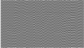
Let us suppose that one-dimensional moiré grating with the pitch of the grating λ0=5.4 mm is used to encode the background and another moiré grating with the pitch λ1=5.94 mm is used for the secret information. The embedding of the secret information into the moiré grating requires phase regularization algorithm as well as random phase scrambling algorithm [12]. Such an encoding scheme completely hides the secret in the stationary cover image. Note that the deflections from the state of equilibrium must be one-directional, moreover the direction of the oscillations must coincide with the longitudinal coordinate of one-dimensional moiré grating. Let us analyze the example in Fig. 1: the original secret image is shown in Fig. 1(a), the secret image encoded in the stochastic grating is presented in Fig. 1(b).
Fig. 1The encoding procedure: a) the secret image and b) the encoded image

a)
b)
Two main elements are required for the experimental setup, which is used for the decoding: shaking-table and the digital camera. Firstly, the cover image (Fig. 1(a)) is printed by the ordinary digital printer and is glued onto the rigid surface, which is fixed to the head of the shaking table. Construction should be stable and do not vibrate according its eigen-frequencies at the same time when it is being oscillated according to the preselected law of motion. It must be noted, that the visual decoding procedure is based on the in-plane (not out-of-plane) vibrations only.
Structural parasitic oscillations of the construction emerging due to a poor fastening, some certain internal cracks or loosenings may cause undesired vibrations of the panel itself, which in turn may affect the proper visual decoding of the secret image. An experiment was carried out in order to investigate the eigen-values of the supporting structure. The experimental setup consists of generator of oscillations, shaking table, panel that is used to attach the accelerometer, signal analyzer, signal amplifier (Fig. 2). Three-axis accelerometer is attached to the construction and is used to register motion along three axes: motion from top to bottom – on x axis, motion perpendicular to the plate – on y axis, motion from right to left – on the z axis. Generator Agilent 33220A is used to generate 1 Hz rectangular shape frequency pulses up to 200 ms. The accelerometer measurements obtained in the direction of x axis (Fig. 3) are not very precise, whereas the pulses are being excited along this axis. Rectangular form of motion is selected to facilitate the excitation of eigen-forms and eigen-frequencies of the equipment. Fourier transformation of the pulse includes all frequencies and, inversely, the white noise transformation is a single pulse. To avoid using only pulse responses, a rectangular signal is supplied, which means that white noise excitation is constantly maintained, and all frequency components that are present in this construction are excited. In this way, hidden construction frequencies related to the cracks in the construction, imperfections of welding points or loosenings of the construction will sound “richer”, and particularly such frequencies may cause undesired oscillations, for example, in the transverse direction. Signal implementation in time domain is shown in Fig. 3(a), (c), (e).
Fig. 2Experimental equipment for verification of reliability of the construction
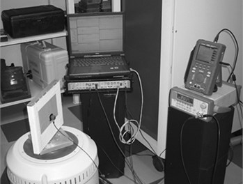
Fig. 3Time-domain implementation of the rectangular signal and amplitudes emerging at particular frequencies along x, y, and z directions
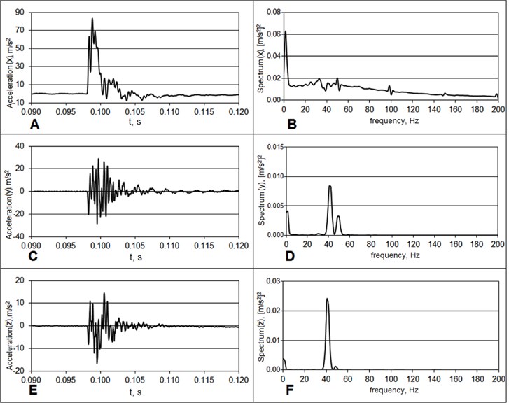
The amplitudes of the received signal induced at the particular frequencies along x, y, and z directions are shown in Fig. 3(b), (d), and (f). The excited signal can be seen in x direction as the amplitude of the signal in x direction is high, while it is almost equal to zero in y and z directions. It means that the construction is reliable: it oscillates along x axis, while there is almost no signal in other directions. The main amplitudes of the Fourier spectrum along direction of x axis are concentrated at low frequencies, i.e. at such frequencies that are used to excite the construction. Resonant frequencies along y and z directions are obtained further from the origin of the spectrum. Construction has higher parasitic frequencies, although they are sufficiently far from the values that we are interested in. If the experiment is carried out for the frequencies up to 30 Hz, then these parasitic frequencies exist at 300 Hz. Therefore, this factor has no negative impact on the visual cryptography decoding system.
It can be noted, that this investigation has been conducted just with aim to validate the special supporting construction of the experimental equipment which is attached to the shaking-table. Let’s assume, that dynamic visual cryptography is applied to monitor any oscillating surface in industrial engineering applications. In such a scenario the encoded image printed on a sticky film should be glued directly to the investigated surface. Then, no parasitic eigen-frequencies or eigen-forms would emerge.
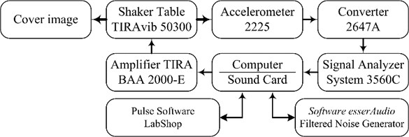
The schematic diagram of the experimental setup is shown in Fig. 4. Shaking-table TIRAvib 50300 is controlled using amplifier TIRA BAA 200-E. Noise-generating software EsserAudio produces white noise and transfers it through the low-frequency filter (the frequency range is set from 0 to 100 Hz), then the signal is transmitted to the amplifier. The encoded image is glued on the head of the shaking-table that is also used to attach a lightweight piezoelectric accelerometer Endevco 2225 with sensitivity of 0,07655 pC/m/s2. The construction itself is mounted on the working surface of the shaking-table, while the output of the accelerometer is connected to the analyzer “Pulse Multi-analyzer system Type 3560” via charge-to-voltage converter type 2647A with amplification of 1 mV/pC; the entire process is controlled using Bruel&Kjaer Pulse LabShop.
Hence, not only the low-frequency chaotic oscillations are created, but the waveform of the oscillations impacting the shaking-table is controlled as well. In other words, there is a possibility to set, observe, and control the parameters of chaotic oscillations.
Fig. 4The schematic diagram of the experimental setup
4. Experimental results
At first the encoded image presented in Fig. 1(a) is glued on the vertical panel, which is fixed to the head of the shaking table (Fig. 2). The filtered noise generator is set to generate 30 s duration white noise signals and pass it through the low-pass filter (the peak frequency is located at 30 Hz). The low pass filter is used for the mimicking of the non-linear vibrations of the mechanical systems (the shaking-table is not capable to produce oscillations with the frequency of 10 kHz.)
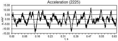
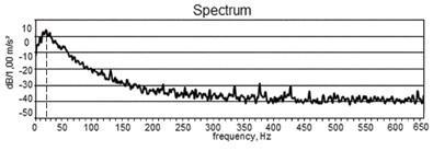
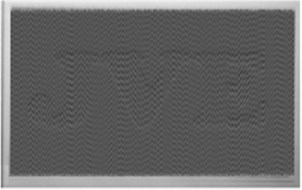
The motion produced by the shaking table is registered by the piezoelectric accelerometer (Fig. 2). The recorded signal is presented in Fig. 5(a). The spectrum of the recorded signal is shown in Fig. 5(b). It can be clearly seen that maximum is reached when the oscillation frequency is equal to 22 Hz, what almost corresponds to the peak frequency of the low pass filter. It can be noted that 25-30 Hz is a sufficient frequency of harmonic oscillations in order to interpret time-averaged image by a naked eye [13]. This fact can also explain application of dynamic visual cryptography for the chaotic oscillations. The same applies to the digital camera as well – exposure time has to be long enough to span a sufficient number of intervals of oscillation-related process. In Fig. 5(a), the exposure time is 0.63 s and is not sufficient to represent a typical waveform of chaotic oscillations, but long enough for us to interpret a secret image by a naked eye. We notice, that the image perceived by a naked eye is clearer than obtained using a digital camera (Fig. 6(b)) (this fact is related to a short exposure time).
During the experiment, the parameters of the input signal do not change; the only parameter that varies is the amplification of the control signal. The encoded image remains in the initial position when the standard deviation from the state of equilibrium is zero – the secret image in the encoded picture is invisible. The standard deviation of the values of random chaotic oscillations increases when the amplification is increased. A secret image is presented in Fig. 6(b), although the time-averaged fringes are not formed in locations of either a secret image or the background. Fig. 6(a) demonstrates the time-averaged image obtained using computer modeling in case of harmonic oscillations.
Fig. 5a) The recorded signal and b) the spectrum of the recorded signal
a)
b)
Fig. 6Decoding of the secret information: a) the computer generated decoded image; b) the secret image obtained by the digital camera (exposure time is 0,63 s)

a)
b)
5. Conclusions
Time-averaged fringes are not developed in time-averaged image if the cover is oscillated chaotically. In this case time-averaged cover image becomes continuously blurred if only the intensity of chaotic oscillations is sufficiently high. Although the rate of the contrast decay is quite sensitive to the pitch of the moiré grating. This visual effect allows the construction of the visual cryptography scheme, which enables the interpretation of the secret information by a naked eye, if only the observed cover image oscillates chaotically. Moreover, the pitch of the moiré grating used for the encoding can be preselected before the experiment in such a way that the secret image becomes visible only at a pre-determined intensity of chaotic oscillations. Intensity of oscillations can be governed by the power supply or the control panel of the shaking table.
Thus, such optical technique can be effectively employed for the assessment of the chaotic processes by a naked eye. The cover image can be printed and attached on the surface, which should be monitored. The secret image will not be visible if the surface does not oscillate and it will appear when the structure performs predefined chaotic oscillations. This method does not require any additional costs. Moreover, it can be applied in any transparent environment: in vacuum or in liquids.
References
-
Naor M., Shamir A. Visual cryptography. Workshop on the Theory and Application of Cryptographic Techniques, Vol. 950, 1995, p. 1-12.
-
De Prisco R., De Santis A. Color visual cryptography schemes for black and white secret images. Theoretical Computer Science, Vol. 510, 2013, p. 62-86.
-
Tsai D.-S., Horng G., Chen T.-H., Huang Y.-T. A novel secret image sharing scheme for true-color images with size constraint. Information Sciences, Vol. 179, Issue 19, 2009, p. 3247-3254.
-
Wang R.-Z., Lan Y.-C., Lee Y.-K., Huang S.-Y., Shyu S.-J., Chia T.-L. Incrementing visual cryptography using random grids. Optics Communications, Vol. 283, Issue 21, 2010, p. 4242-4249.
-
Yang C.-N., Ciou C.-B. Image secret sharing method with two-decoding-options: lossless recovery and previewing capability. Image and Vision Computing, Vol. 28, Issue 12, 2010, p. 1600-1610.
-
Shyu S. J. Image encryption by random grids. Pattern Recognition, Vol. 40, Issue 3, 2007, p. 1014-1031.
-
Shyu S. J. Image encryption by multiple random grids. Pattern Recognition, Vol. 42, Issue 7, 2009, p. 1582-1596.
-
Kobayashi A. S. Handbook on Experimental Mechanics. 2nd Edition, SEM Bethel, CT, 1993.
-
Patorski K., Kujawinska M. Handbook of the Moiré Fringe Technique. Elsevier, Amsterdam, 1993.
-
Desmedt Y., Van Le T. Moiré cryptography. 7th ACM Conference on Computer and Communications Security, 2000, p. 116-124.
-
Ragulskis M., Aleksa A. Image hiding based on time-averaging moiré. Optics Communications, Vol. 282, Issue 14, 2009, p. 2752-2759.
-
Petrauskienė V., Palivonaitė R., Aleksa A., Ragulskis M. Dynamic visual cryptography based on chaotic oscillations. Communications in Nonlinear Science and Numerical Simulation, Vol. 19, Issue 1, 2014, p. 112-120.
-
Petrauskiene V., Aleksa A., Fedaravicius A., Ragulskis M. Dynamic visual cryptography for optical control of vibration generation equipment. Optics and Lasers in Engineering, Vol. 50, Issue 6, 2012, p. 869-876.

