Abstract
The present paper discusses certain aspects of dynamic modeling of the harmonic drive. In particular, a new original dynamic model of a harmonic drive has been proposed for a power transmission system. The model takes account of nonlinear changes in stiffness, as well as damping. The proposed model of a harmonic drive in the power transmission system is investigated in the Matlab-Simulink environment. Utilization of the identified, developed dynamic model will allow to expand the knowledge about torsional vibration which are present in power transmission systems equipped with harmonic drive as well as it will contribute to a reduction of expenses connected with performing costly experimental tests.
1. Introduction
Toothed gears are widely used in the systems transmitting mechanical power of transport machine. They are also used in both simple everyday articles and very complex devices produced usually in single units. Since it is impossible to describe real phenomena or processes accurately, the practice is to adopt a model corresponding with reality to some limited extent and providing approximate (qualitatively and quantitatively) results comparable with observation and test results. This comparison helps to assess usability of the model in solving given constructional problem. The adapted dynamic model of a gear, with a proper structure and respecting all significant factors influencing meshing teeth loads and their distribution may be a useful tool in the design of toothed gears characterized by long lifetime. For the above reasons, lots of scientific research centers around the world have developed more and more perfect dynamic models of toothed gears and complete drive systems with gears. Due to difficulties arising in solving differential equations of motion these models were characterized by low number of degrees of freedom at first. Over the years the models have evolved in two following directions:
• Accurate analysis of gear isolated from the drive system; the only causes of dynamic loading are internal, and the external load is constant;
• Investigation of dynamic properties of complete drive systems consisting of a motor, toothed gear, principal process machine, shafts, couplings and intermediate elements; simplified dynamic models of meshing are used.
A harmonic drive consists of a toothed mechanism, which is composed of three main elements (Fig. 1). The circular spline (mark 1in Fig. 1) is a solid steel ring with internal teeth. The flexspline (mark 2 in Fig. 1) is a flexible steel cylinder with external teeth. The drive is executed by the wave generator (mark 3 in Fig. 1), a thin-race ball bearing that is fitted onto an elliptical plug. The flexspline is the main component of a harmonic drive, which can generate a repeated vibration by the wave generator. From this reason, the flexspline should have flexibility and good vibration characteristics. The elliptical cam wave generator is inserted into the bore of the flexspline, it forms it into an elliptical shape. The wave generators are enclosed in a ball-bearing assembly that function as the rotating input element. When the wave generator transfers its elliptical shape onto the flexspline, then the external teeth of flexspline are engaged with the internal circular spline teeth in two opposed locations. The shaft attached to the flexspline is the rotating output element.
Fig. 1Principal members of the harmonic drive, type HDUC [1]: 1 – the rigid circular spline, 2 – the flexible flexspline, 3 – the ellipse-shaped wave generator
![Principal members of the harmonic drive, type HDUC [1]: 1 – the rigid circular spline, 2 – the flexible flexspline, 3 – the ellipse-shaped wave generator](https://static-01.extrica.com/articles/15571/15571-img1.jpg)
The schematic view of a harmonic drive in four operating positions is shown in Fig. 2. The ball bearing mounted on the elliptical wave generator deforms the flexspline, thus engaging teeth at diametrically opposite points coincident with the major axis of the elliptical wave generator and disengaging points at the minor axis (Fig. 2(a)). When the circular spline is fixed, the rotation of the wave generator produces a reverse motion of the flexspline (Fig. 2(b), (c)). If the rigid circular spline has two teeth more than the flexspline, then a single revolution of the wave generator rotates the flexspline backward about two teeth (Fig. 2(d)).
Fig. 2The operating positions of a harmonic drive [1]: a) the elliptical shape of the wave generator causes the teeth of the flexspline to engage the circular spline at two regions at opposite ends of the major axis of the ellipse, b) as the wave generator rotates the zone of tooth engagement travels with the major axis of the ellipse, c) for each 180° clockwise movement of the wave generator the flexspline moves counterclockwise by one tooth relative to the circular spline, d) each complete clockwise rotation of the wave generator results in the flexspline moving counterclockwise by two teeth from its previous position relative to the circular spline
![The operating positions of a harmonic drive [1]: a) the elliptical shape of the wave generator causes the teeth of the flexspline to engage the circular spline at two regions at opposite ends of the major axis of the ellipse, b) as the wave generator rotates the zone of tooth engagement travels with the major axis of the ellipse, c) for each 180° clockwise movement of the wave generator the flexspline moves counterclockwise by one tooth relative to the circular spline, d) each complete clockwise rotation of the wave generator results in the flexspline moving counterclockwise by two teeth from its previous position relative to the circular spline](https://static-01.extrica.com/articles/15571/15571-img2.jpg)
a)
![The operating positions of a harmonic drive [1]: a) the elliptical shape of the wave generator causes the teeth of the flexspline to engage the circular spline at two regions at opposite ends of the major axis of the ellipse, b) as the wave generator rotates the zone of tooth engagement travels with the major axis of the ellipse, c) for each 180° clockwise movement of the wave generator the flexspline moves counterclockwise by one tooth relative to the circular spline, d) each complete clockwise rotation of the wave generator results in the flexspline moving counterclockwise by two teeth from its previous position relative to the circular spline](https://static-01.extrica.com/articles/15571/15571-img3.jpg)
b)
![The operating positions of a harmonic drive [1]: a) the elliptical shape of the wave generator causes the teeth of the flexspline to engage the circular spline at two regions at opposite ends of the major axis of the ellipse, b) as the wave generator rotates the zone of tooth engagement travels with the major axis of the ellipse, c) for each 180° clockwise movement of the wave generator the flexspline moves counterclockwise by one tooth relative to the circular spline, d) each complete clockwise rotation of the wave generator results in the flexspline moving counterclockwise by two teeth from its previous position relative to the circular spline](https://static-01.extrica.com/articles/15571/15571-img4.jpg)
c)
![The operating positions of a harmonic drive [1]: a) the elliptical shape of the wave generator causes the teeth of the flexspline to engage the circular spline at two regions at opposite ends of the major axis of the ellipse, b) as the wave generator rotates the zone of tooth engagement travels with the major axis of the ellipse, c) for each 180° clockwise movement of the wave generator the flexspline moves counterclockwise by one tooth relative to the circular spline, d) each complete clockwise rotation of the wave generator results in the flexspline moving counterclockwise by two teeth from its previous position relative to the circular spline](https://static-01.extrica.com/articles/15571/15571-img5.jpg)
d)
2. Dynamic model of harmonic drive in power transmission system
Since the invention of harmonic drive in 1959, numerous researchers and designers have devoted their attention to the dynamic phenomena in harmonic drives. First important studies concerning this subject matter were published in [2-3]. Tuttle and Seering, [4-5], carried out dynamic tests consisting of a number of experiments which involved a transmission working in an idle running mode. In their papers, they worked out various dynamic models of transmission, which differed in the assumptions and simplifications. Their most complete model took into account the kinematic error, nonlinear stiffness and interaction between the gear teeth with friction losses. In their paper [6], Kircanski and Goldenberg proposed a dynamic model of a harmonic drive based on tests of a transmission with blocked load. In the research, however, they used simple models of damping and friction. Among the papers which contributed a great deal to the research on the dynamics of harmonic drives, one should enumerate the publications by Seyfferth [7], Taghirad [8] and Al-Bender [9]. The studies of these authors mostly concern an extremely vital problem of correct modeling of nonlinear torsional stiffness and damping of a flexspline in a harmonic drive as well as the problem of taking into account proper models of friction in bearings and meshing. The papers concerning the dynamics of harmonic drive, published by W. Ostapski, are also worth mentioning [10]. In his numerous studies he made use of two dynamic models. The first concerned a simple model of a power transmission system with a harmonic drive. It had one degree of freedom and described torsional vibration of a flexspline in a harmonic drive. The model enabled examining the effect of: moments of inertia, the value and nature of elasticity forces and damping distribution, as well as backlash and changes of induction on the amplitude and torsional vibration frequency of a power transmission system with a harmonic drive. The second model concerned the dynamics of a flexspline separated from the power transmission system, and assuming proper boundary conditions and reactions in the toothed area, as well as an cooperation with the generator. In this case, a nonlinear continuous model using geometric equations of the nonlinear elastic theory of thin-walled coatings was applied.
While analyzing the results of the author’s own studies [13-14] and those of other authors [2-12], it has been found that the problems of modeling the harmonic drive in a power transmission system have not yet been completely solved. Which is why the authors have worked out a proposal of a dynamic model of a harmonic drive operating in a power transmission system.
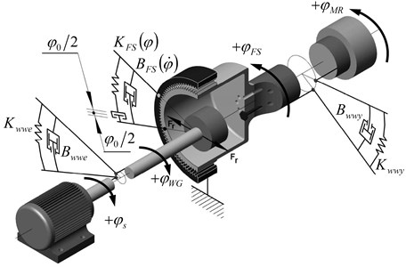
The model obtained in Matlab-Simulink [15] takes into account the interactions of different internal and external factors that occur during gear operation in power transmission system. The model presented in Fig. 3 takes into account the work of an electric motor, a single-stage harmonic drive and a working machine.
Fig. 3Dynamic model of a power transmission system with a harmonic drive
The equations of motion take the following form:
+Kwwe⋅(φs-φWG)-BFSu⋅(˙φWGu-˙φFS)-KFSu⋅(φWGu-φFS)=0,
+KFS⋅(φWGu-φFS)-Bwwy⋅(˙φFS-˙φMR)-Kwwy⋅(φFS-φMR)=0,
where: Js – the moment of inertia of the engine rotor, Jwwe – the moment of inertia of the drive’s input shaft and of the wave generator, Jwwy – the moment of inertia of the drive’s output shaft drive and of the flexspline, JWG – the moment of inertia of the wave generator, JFS – the moment of inertia of the flexspline, JMR – the moment of inertia of the working machine, reduced to the wave generator axis, Bwwe – the damping coefficient of torsional vibration of the harmonic drive’s input shaft, Bwwy – the damping coefficient of torsional vibration of the harmonic drive’s output shaft, BFS – the damping coefficient of torsional vibration of the flexspline, Kwwe – torsional stiffness of the harmonic drive’s input shaft, Kwwy – torsional stiffness of the harmonic drive’s output shaft, KFS – torsional stiffness of the flexspline, Mn(˙φs) – torque of the engine, MMR(t) – variable in time load torque coming from the working machine, w1=w2=w3=w4=0.5 – coefficients taking into account the distribution of the moment of inertia, φs – rotation angle of the engine rotor, φWG – rotation angle of the wave generator, φFS – rotation angle of the flexspline, φMR – rotation angle of the working machine shaft, u – absolute value of the gear ratio.
Synchronous and asynchronous electric motors are universally used for machine and device drives. Many different advanced models of electric motors are known. Ready-made computer software simulating operation of asynchronous motors is available (e.g. model included in Simulink programme [15]). From the point of view of toothed gear dynamics these models are too complex, since they compute lots of electrical parameters useless in the toothed gears modelling, and this lengthens computational time. That is why asynchronous motor model using torque-speed characteristic of the motor and rotor’s moment of inertia has been used in current research:
where Mn is motor’s driving torque, Nm; Ms(n) is torque of the motor calculated from torque-speed characteristic (Fig. 4); n is rotational speed of the shaft, RPM; ¨φS is angular acceleration of the motor shaft, rad/s2; ˙φS is angular speed of the motor shaft, rad/s.
Fig. 4Torque-speed characteristic of asynchronous motor [15]
![Torque-speed characteristic of asynchronous motor [15]](https://static-01.extrica.com/articles/15571/15571-img7.jpg)
Torsional stiffness of shafts may be determined for example on the basis of dependencies given in [16, 17, 21]. Some authors assume that the stiffness of shafts is high in relation to that of the flexspline. In such case, the model takes the form of only two differential equations [16]. Stiffness of the flexspline is nonlinear and, moreover, there is a certain backlash in harmonic drives. The typical shape of the stiffness curve consists of two characteristic properties: increasing stiffness with displacement and hysteresis loss. Therefore, the drive manufacturer [1] recommends using a piecewise linear approximations between the points provided in the catalogue (Fig. 5), which describe changes in stiffness. The torsional stiffness may be evaluated by dividing the torque-torsion curve into three regions. When output torque equal is zero an output rotation angle is:
A low torque region in which T≤T1 and:
A middle torque region in which T>T1 and:
A high torque region in which T>T2 and:
where: T – output torque [Nm], φi – output rotation angle [rad], φ0 – lost motion [arc min], Ki – spring constant [Nm/rad].
Sample results of the calculations of the torsion angle φi according to the Eqs. (7)-(10) for HDUC 32-100 shown in Table 1 and on Fig. 5. The values of Ki and φ0 quoted in the Table 1 are the average of measurements made during numerous practical tests [1]. Other authors [3, 12], use approximation with a third degree polynomial for a description of changes in stiffness (Fig. 6).
Fig. 5Recommended method for determining the torsional stiffness by the manufacturer [1]
![Recommended method for determining the torsional stiffness by the manufacturer [1]](https://static-01.extrica.com/articles/15571/15571-img8.jpg)
Fig. 6Examples of changes in torsional stiffness (HDUC 32-100) – a cubic polynomial approximation
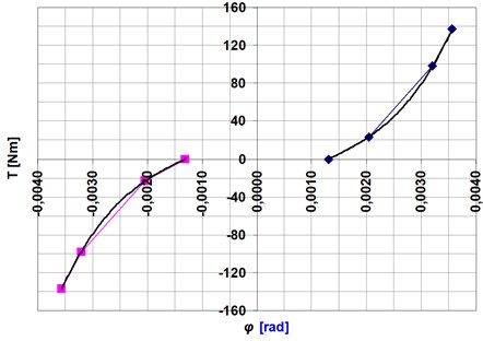
Other models of the flexspline stiffness can be found in papers [4-10]. Taghirad [8] proposed an advanced hysteresis model of torsional stiffness in the flexspline. He assumed that the hysteresis mainly came from the structural damping of the flexspline. Seyfferth [7] offered to model the hysteresis as a combination of Coulomb friction and a weighted friction function, represented by a hyperbolic function to capture the pre-sliding friction behaviour. However, all these authors have encountered the problem of correct modelling of changes a torsional stiffness of the harmonic drive. Interesting can be consideration of influence of modern repair technology on the mechanism properties, i.e. [18-20]. For example, in work [10] can be found the following description of nonlinear changes a torsional stiffness:
Using the values of the parameters a and c equal to zero Eqs. (11) and (12) can be reduced to the form:
Table 1Sample results of the calculations of the torsion angle for HDUC 32-100 [1]
The torsion angle φi [rad] | |
Eq. (7): φ0=9 [arc min] | φ=1.31∙10-3 |
Eq. (8): φ0=9 [arc min], T=23.5 [Nm], K1= 3.2∙104 [Nm/rad] | φ=2.04∙10-3 |
Eq. (9): φ0=9 [arc min], T1=23.5 [Nm], T= 98 [Nm], K1=3.2∙104 [Nm/rad], K2=6.4∙104 [Nm/rad] | φ=3.21∙10-3 |
Eq. (10): φ0= 9 [arc min], T1= 23.5 [Nm], T2= 98 [Nm], T= 137 [Nm], K1= 3.2∙104 [Nm/rad], K2= 6.4∙104 [Nm/rad], K3= 11∙104 [Nm/rad] | φ=3.56∙10-3 |
In this case, after crossing the turning angle of the backlash of at φ0= 9 [arc min] for HDUC 32-100 gear stiffness increases to a certain value (Fig. 7). Changes of the stiffness which shown on Fig. 7 do not correspond the correct changes of the stiffness.
Fig. 7Incorrect changes of the stiffness (screen from Matlab-Simulink)
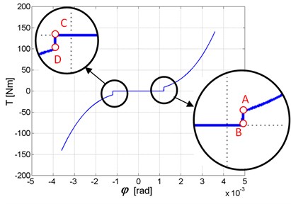
Fig. 8Changes of the stiffness (screen from Matlab-Simulink)
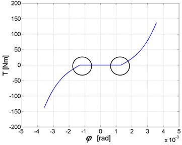
On the basis of an analysis of the data contained in the literature, the authors of this paper proposed the following description of nonlinear changes in stiffness:
where: φ0 most often amounting, depending on the manufacturer and the drive type, to 2.9∙10-4-26∙10-4 [rad] (1-9 [arc min]), am, bm, cm, dm – stiffness polynomial coefficients for a case where: -∞<φ<-φ0/2, ap, bp, cp, dp – stiffness polynomial coefficients for a case where: φ0/2<φ<∞.
Examples of changes in stiffness obtained by the authors (Eqs. (15)-(17)) for harmonic drive HDUC 32-100 (φ0=9 [arc min]) are shown in Fig. 8.
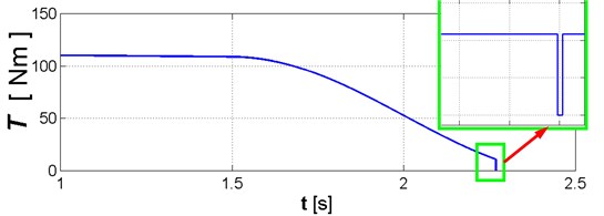
The description of torsional stiffness of flexspline and mesh stiffness is given in Eqs. (11)-(14). When load torque (Fig. 9) takes on positive value lower than value corresponding to point A in Fig. 7, the torsional stiffness of flexspline and mesh stiffness is assumed to be equal zero; this causes an increase of φ angle. This in turn results in sudden increase of torsional stiffness corresponding to rotating torque greater than value tallying to point A in Fig. 7. The results obtained when this effect is present are shown in Fig. 10. The outcome of this mathematical description of torsional stiffness (Eqs. (11)-(14)) is artificial excitation of vibrations, caused by change in rigidity similar to step-wise change; in “real life” this kind of change does not occur. If variable integration step is used in numerical calculations, this causes additional decrease in length of integration step and, in opinion of the authors of current paper, leads to false calculation results accompanied by lengthening of calculation time [22].
Fig. 9Change in load torque MMR
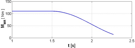
Fig. 10Change in rotating torque due to change in torsional stiffness described by Eqs. (11)-(14)
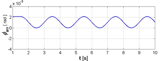
The authors also think that it may be possible to conduct simulations and obtain reliable results using description of torsional stiffness given in Eqs. (11)-(14), but they perceive limitations which involve values of load torques which make it possible to avoid the range between points D and A in torsional stiffness curve (Fig. 7); apart from case when the gear is loaded with very low torque it may occur during operation within the range of resonance frequency of drive system. For the above stated reasons the authors propose to use description of meshing stiffness shown in Eqs. (15)-(17). The sample values of output shaft torsional angle φWY=φMR-φFS with length of engagement 70 mm and diameter 26 mm are shown in Fig. 11.
3. Conclusions
Proposition of a model of harmonic drive in the power transmission system executed in the Matlab-Simulink environment has been presented in current paper. Particular attention has been paid to different mathematical description of torsional stiffness of flexspline and mesh stiffness; their impact on simulation results has been presented in case of variable (in time) and relatively small values of load torque. The analysis will be continued using presented models and results of the simulation will be compared with experimental results. Utilization of the identified, developed dynamic model will allow to expand the knowledge about torsional vibration which are present in power transmission systems equipped with harmonic drive as well as it will contribute to a reduction of expenses connected with performing costly experimental tests.
Fig. 11Changes of: a) load torque, b) obtained simulation result of output shaft torsional angle φWY, accomplished by using description of flexspline rigidity and meshing stiffness provided by Eqs. (15)-(17)

References
-
General Catalogue Harmonic Drive AG, 05.2009.
-
Aliev N. A. A study of the dynamic behavior of flexible gears in harmonic drives. Soviet Engineering Research, Vol. 66, Issue 6, 1986, p. 7-11, (in Russian).
-
Volkov D. P., Zubkov Y. N. Vibrations in a drive with a harmonic gear transmission. Russian Engineering Journal, Vol. 58, Issue 5, 1978, p. 11-15, (in Russian).
-
Tuttle T. D., Seering W. A nonlinear model of a harmonic drive gear transmission. Proceeding of IEEE Transaction on Robotics and Automation, Vol. 12, Issue 3, 1996, p. 368-374.
-
Tuttle T. D., Seering W. Modeling a harmonic drive gear transmission. Proceeding of IEEE International Conference on Robotics and Automation, 1993, p. 624-629.
-
Kircanski N., Goldenberg A., Jia S. An experimental study of nonlinear stiffness, hysteresis and friction effects in robot joint with harmonic drives and torque sensors. Proceeding of the third international Symposium on Experimental Robotics, 1993, p. 147-154.
-
Sefferth W., Maghzal A. J., Angeles J. Nonlinear modeling and parameter identification of harmonic drive robotic transmissions. Proceeding of IEEE International Conference on Robotics and Automation, 1995, p. 3027-3032.
-
Taghirad H. D., Belanger P. R. An experimental study on modeling and identification of harmonic drive systems. Proceeding of IEEE Conference on Decision and Control, 1996, p. 4725-4730.
-
Al-Bender F., Symens W., Swevers J., Van Brussel H. Theoretical analysis of the dynamic behavior of hysteresis elements in mechanical systems. International Journal of Nonlinear Mechanics, Vol. 39, 2004, p. 1721-1735.
-
Ostapski W. The problems of harmonic drive modelling. Scientific Books of the Silesian Technical University, series of Mechanics, Vol. 121, 1995, p. 261-266, (in Polish).
-
Ostapski W. Harmonic drive. Warsaw University of Technology Publishing House, 2011, (in Polish).
-
Hidaka T., Ishida T., Zhang Y., Sasahara M., Tanioka Y. Vibration of a strain-wave gearing in an industrial robot. Proceedings of the International Power Transmission and Gearing Conference, 1990, p. 789-794.
-
Folęga P. The problems of the harmonic drive dynamics modeling. Scientific Books of the Silesian Technical University, series of Transport, Vol. 63, 2006, p. 125-132, (in Polish).
-
Folęga P., Wojnar G. Proposition of a dynamic model of harmonic drive. Scientific Books of the Naval University of Gdynia, Vol. 178A, 2009, p. 81-87, (in Polish).
-
Simulink Dynamic system Simulation for Matlab. Using Simulink version 3. The Math Works, Inc. 1999, p. 210.
-
Dąbrowski Z., Maksymiuk M. Shafts and axles. PWN, Warsaw, 1984, p. 167, (in Polish).
-
Dolecek R., Novak J., Cerny O. Experimental research of harmonic spectrum of currents at traction drive with PMSM. Radioengineering, Vol. 20, Issue 2, 2011, p. 512-515.
-
Lisiecki A. Welding of titanium alloy by disk laser. Proceedings of SPIE, Laser Technology, Vol. 8703, 2013.
-
Węgrzyn T., Piwnik J., Łazarz B., Hadryś D. Main micro-jet cooling gases for steel welding. Archives of Materials and Metallurgy, Vol. 58, Issue 2, 2013, p. 551-553.
-
Węgrzyn T. The classification of metal weld deposits in terms of the amount of nitrogen. Conference of International Society of Offshore and Polar Engineers, Seattle, USA, 2000, p. 130-134.
-
Dąbrowski D., Batko W., Cioch W., Plascencia-Mora H. Model of the gears based on multibody system and its validation by application of non-contact methods. Acta Physica Polonica, Vol. 123, Issue 6, 2014.
-
Burdzik R. Implementation of multidimensional identification of signal characteristics in the analysis of vibration properties of an automotive vehicle’s floor panel. Maintenance and Reliability, Vol. 16, Issue 3, 2014, p. 439-445.
