Abstract
In order to investigate the characteristics of bifurcation and chaos for a spur gear pair system, a three-degree-of-freedom nonlinear dynamic model with multi-clearance is established, in which time-varying meshing stiffness, static transmission error, gear backlash and bearing clearance are comprehensively taken into account. Through introducing a relative generalized coordinate, the dimensionless dynamic equations of motion of system are derived and then solved by using Runge-Kutta numerical integration method. And the bifurcation and chaos features of gear pair are systematically analyzed and discussed from bifurcation diagrams with meshing frequency, gear backlash, bearing clearance and damping ratio as control parameters under different loaded conditions. Meantime, with the help of Poincaré map and phase diagram, the motion forms of system are accurately identified. The analysis results reveal that as meshing frequency increases, the system shows various types of motion states which contain periodic motion, quasi-periodic motion and chaotic motion. Similarly, with the increasing of gear backlash, the system undergoes complex motion forms under lightly loaded condition, whereas it is only in period-one motion state under heavily loaded condition. Furthermore, the system motion state is gradually switched from chaos to periodic or quasi-periodic motion under lightly loaded condition when bearing clearance changes. However, under heavily loaded condition, the bearing clearance has a weak effect on dynamic behavior of the gear system. Apparently, the system tends to be more stable under heavily loaded condition than that under lightly loaded condition. In addition, the growing damping ratio can effectively suppress the chaotic behavior and control nonlinear vibration of gear system. The research results provide useful guidance for dynamic design and vibration control for gear set.
1. Introduction
Gear system is a type of power and motion transmission equipment. Owing to compact structure, small volume, high transmission efficiency and reliable performance, it is widely applied to various mechanical engineering fields, such as automobile, aerospace, ship, robot and so forth. However, due to time-varying meshing stiffness, gear backlash, bearing clearance and static transmission error, the nonlinear vibration is frequently caused in gear system, which leads to negative effect on system performance and stability. Therefore, studying the nonlinear dynamic properties of gear system from the aspect of improving the accuracy of gear transmission and suppressing vibration and noise is quite important.
Based on nonlinear dynamics theory, a great number of researches on nonlinear dynamics of gear system have been done in recent decades. For convenience of research, the gear system is invariably simplified to the single-degree-of-freedom (SDOF) model, two-degree-of-freedom (TDOF) model or multiple-degree-of-freedom (MDOF) model by using lumped mass method. As an example, Kahraman [1] established a SDOF model to analyze the nonlinear dynamic characteristics of a spur gear pair system, which considered the internal excitation and backlash. For the purpose of further studying the nonlinear dynamic behaviors of the gear system, a MDOF gear-rotor-bearing model was developed with linear time-invariant meshing stiffness and time-varying meshing stiffness respectively by Kahraman [2, 3], where gear backlash and bearing clearance were involved in the model. Based on the MDOF model Kahraman [3] proposed, Raghothama [4] utilized the incremental harmonic balance method (IHBM) to investigate the periodic and chaotic motions of geared rotor-bearing system and then verified the analysis results based on numerical integration method. Likewise, with consideration of backlash and time-dependent meshing stiffness, Theodossiades [5] employed the analytical methodology method to analyze the dynamics for a gear pair system and demonstrated the accuracy of the analytical methodology by comparing the analysis solutions to numerical solutions. In Ref. [6], Litak studied the different dynamic features of a gear pair system with and without the additional DOF, respectively.
The key system parameters, which consist of gear meshing damping, support stiffness, meshing frequency, gear backlash and so on, have great influence on the dynamics of a gear set. Hence, it is of importance to analyze in detail the effect of these above parameters on the dynamic response of gear system. Wang [7] developed a nonlinear dynamic model for a gear-rotor-bearing system with MDOF, which took multiple clearances and time-varying stiffness into consideration to briefly study the bifurcation and chaos with support stiffness and meshing frequency as control parameters. They found that there exist complex bifurcation phenomena and chaotic behavior in the gear system with the change of support stiffness and bearing clearance. Then, Al-shyyab [8, 9] simplified two gear pairs system to a TDOF model and obtained the periodic and sub-harmonic responses by using a multi-term HBM. Meantime, the effects of several system parameters such as gear mesh damping, meshing stiffness amplitude and static torque transmitted were described. In addition, in order to analyze the nonlinear dynamics of a spur gear pair, a SDOF model was proposed by Shen [10], in which time-varying stiffness, gear backlash and static transmission error were considered. Also, the influence of damping ratio and excitation amplitude was studied by applying IHBM. Similarly, to examine the influence of gear backlash on dynamics of two stage gear system, Walha [11] presented a torsional dynamic model for two spur gear pairs with backlash. The dynamic behaviors of the system were analyzed by using Newton-Raphson algorithm.
Chang-Jian [12] performed the dynamic responses of a gear-bearing system with nonlinear suspension and revealed the motion states of the system observed from phase diagrams, power spectra, Poincaré maps and Lyapunov exponents. Subsequently, the above diagrams were also used to systematically analyze the dynamic behaviors of a spur gear system with and without nonlinear suspension by Chang-Jian [13]. Considering dynamic backlash, friction and time varying stiffness, Chen [14] developed a MDOF model for a gear pair system. Then, the model was solved by numerical integration method to analyze and predict the system motion states. According to the above SDOF model, Moradi [15] carried out the nonlinear oscillations with backlash nonlinearity, and investigated the forced vibration responses of the gear system including primary, super-harmonic and sub-harmonic resonances based on the multiple scale method. Farshidianfar [16] formulated a generalized nonlinear time-varying dynamic model of a spur gear pair, in which gear backlash, time varying stiffness, external excitation and static transmission error were considered. Meanwhile, the global bifurcation and transition to chaotic behaviors of the gear system were studied by means of Melnikov analytical analysis. Liu [17] established a TDOF torsional model for a spur gear pair system with meshing stiffness, backlash, transmission error and external periodic excitation. And the influences of rotational speed, backlash and mesh damping coefficient on the dynamic characteristics of the gear system were obtained by using Newmark method. Similarly, Gou [18] developed a MDOF model of a spur gear pair system with backlash. The nonlinear dynamic characteristics of the system were analyzed with varying of exciting frequency. Then, by using the simple cell mapping method, Gou [19] examined the dynamic characteristics of the multi-parameter coupling in torsion-vibration gear system and analyzed the distribution map and bifurcation diagram in the parameter plane. Additionally, Liu [20] investigated the dynamic response of a gear pair system and interactions between bearing clearance and backlash. The contact force on backside and journal bearing forces and shift of the bearing position were taken into account.
Lots of researches on the nonlinear dynamic characteristics of the gear pair system have been carried out and the corresponding dynamic models were developed as well. However, there are exceedingly few researches on the bifurcation and chaos analysis, especially comprehensively considering gear backlash, bearing clearance, damping ratio and force ratio in gear system. Therefore, in this paper, a dynamic model for a spur gear pair system with MDOF is proposed, in which time-varying meshing stiffness, static transmission error, gear backlash and bearing clearance are considered in the model. The dimensionless dynamic equations of motion are then solved by applying Runge-Kutta numerical integration method. The nonlinear dynamic behaviors of the gear system are analyzed in detail using bifurcation diagram, Poincaré map and phase portrait.
The remainder of this paper is listed as follows: the dynamic model and equations of motion of a gear pair system are established in Section 2. Then, Section 3 presents the numerical simulation results and discussions, where the effect of bifurcation parameters on the nonlinear dynamic responses are analyzed and discussed. Finally, some brief conclusions are drawn from the research in Section 4.
2. Dynamic model and equations of motion
2.1. Model of the gear pair system
A spur gear pair consists of pinion, gear, shafts and bearings. In order to build the dynamic model conveniently and effectively, pinion and gear are modeled as rigid body. Meantime, the shafts and bearings supported the gears are assumed to equivalent elements with viscous damping coefficient and equivalent supported stiffness [17]. Based on the centralized mass method, the nonlinear dynamic model of the gear set is shown in Fig. 1. In the system, the static transmission error, gear backlash, bearing clearance, time-varying meshing stiffness, torque fluctuation, external radial preload, and so forth, are taken into consideration. In addition, teeth modification, profile shifting and friction are neglected in the model.
Fig. 1Nonlinear dynamic model of a spur gear pair system
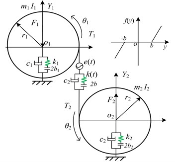
In Fig. 1, it is assumed that the meshing line direction between the two gears is defined as direction of the coordinate system in the gear pair model. Each gear considers a translational degree of freedom () and a rotational degree of freedom (). Here, and mean the equivalent masses of the two gears, respectively; and represent the radius of base circles of the two gears, respectively; and show the moment of inertia of the two gears, respectively; , and 2 ( 1, 2) refer to the equivalent support stiffness, the equivalent support damping and bearing clearance of the two gears, respectively. and are the time-varying meshing stiffness and damping between the two gears, respectively. represents the gear meshing backlash. and are the external radial preload sustained by bearings. Additionally, and are the input torque and output torque impacting on driving gear and driven gear, respectively. Torque ( 1, 2) are composed of mean torque and fluctuation value . Therefore, torque can be expressed as follows:
As shown in Fig. 1, the gear system has four degrees of freedom including two translational degrees of freedom (, ) and two torsional degrees of freedom (, ). When the relative displacement caused by torsional vibration in the gear pair system is , can be described as:
where is the static transmission error of the gear pair system, in which is the fluctuation value and represents the initial phase of error.
When the gear backlash between the driven gear and driving gear is 2, the elastic restoring force can be represented by:
where is the time-varying meshing stiffness, and is the nonlinear backlash function which can be written as:
With the purpose of ensuring the smoothness of gear transmission, the contact ratio of gear pair system is usually under the range of 1 to 2. In other words, the number of tooth pairs will always alternate between one and two in the process of continuous meshing, leading to the generation of dynamic excitation force, where the meshing stiffness shows time-varying property. Thus, the time-varying meshing stiffness can be expressed in Fourier series expansion method as follows:
where is the mean meshing stiffness and is the meshing fundamental frequency. Additionally, and are the expansion coefficient of Fourier series, respectively.
The damping force is defined as:
where is the meshing damping, which can be given as:
where is the damping ratio ( 0.03-0.17).
Hence, the dynamics meshing loads can be expressed as:
2.2. Dynamic differential equations
In terms of the analysis above, the nonlinear dynamic differential equation of a spur gear pair system can be established by using Newton’s second law of motion as follows:
where and are the radical clearances displacement function along direction respectively, which could be expressed as:
However, the above gear pair is a semi-definite system that has rigid body displacement, owing to gear backlash and bearing clearance. It means that the motion equations of the gear system cannot be directly solved by numerical integration method. A new relative coordinate is thus introduced to reduce the dimension of dynamic equation, which will make the equation solvable [21]. As a new degree of freedom, the relative coordinate can be defined as follows:
Therefore, the Eq. (9) can be transferred by substituting the relative coordinate to the following expression:
where and are equivalent mass of the gear pair and the average force related to mean torque respectively, with and .
2.3. Dimensionless equations of motion
In order to compare and analyze the results under the same dimensional scale [21], it is intensely indispensable to make motion equations of gear system dimensionless. Thus, dimensionless time parameter introduced can be defined as with , where is natural frequency of the gear pair system. Meanwhile, displacement of nominal dimension is introduced as well. Then, others parameters, such as displacement, velocity and acceleration could be described by and as follows:
Dimensionless nonlinear clearance function can then be rewritten as:
where and ( 1, 2).
Substituting the dimensionless parameters above into Eq. (12) and then dimensionless equation of motion can be expressed as matrix form:
where is the mass matrix, represents the stiffness matrix, refers to the damping matrix, is the force vector and is the displacement vector. The matrix and vector can be expressed as follows:
where:
3. Numerical results and discussions
Due to the effect of the above nonlinear factors, the gear pair is a complex system with strongly nonlinear and time-variable features. Therefore, it is imperative to investigate the gear set in detail. To reveal the nonlinear dynamic behaviors of the spur gear pair system, the bifurcation and chaos diagrams with the change of bifurcation parameters under different loaded conditions are obtained by using Runge-Kutta numerical integration method. The bifurcation parameters consist of meshing frequency, gear backlash, bearing clearance as well as damping ratio. Furthermore, the phase diagrams and Poincaré maps are used to accurately discuss and analyze bifurcation phenomena and chaotic behavior.
Additionally, external load acted on the gear pair system will be changed under different work conditions which contain heavily loaded condition and lightly loaded condition. And the force ratio can be used to measure the external load, evaluating carrying capacity of gear system. With the increase of force ratio, the carrying capacity of the system is gradually enhanced. Hence, to illustrate the influence of work conditions on the dynamic behaviors for the gear pair system, the bifurcation and chaos features are analyzed with different force ratios [1]. Parameters of gear system are shown in Table 1.
Table 1Parameters of gear system
Parameter | Driving gear/ Driven gear | Parameter | Driving gear/ Driven gear |
Module (mm) | 3 | Moment of inertia (kg·m2) | 8×10⁻⁴ |
Face width (mm) | 25 | Radius (mm) | 40 |
Pressure angle (°) | 20 | Mean mesh stiffness (N/m) | 2×10⁸ |
Tooth number | 25 | Support stiffness (N/m) | 1.2×10⁹ |
Mass (kg) | 1 | Radial preload (N) | 1.6×10⁴ |
3.1. Bifurcation and chaos analysis of the effect of dimensionless meshing frequency
In gear transmission system, meshing frequency is one of important factors which have an important effect on the dynamic response of system. In order to obtain the bifurcation diagrams with the change of dimensionless meshing frequency , some parameters in the gear system are selected as follows: 0.5 or 2, i.e. the gear system is under the lightly loaded condition or under the heavily loaded condition [1], 0.15, 0.25, 1. The bifurcation properties of the gear system with varying are firstly analyzed with 0.5. Then, Fig. 2 shows the bifurcation diagrams of with respect to under lightly loaded condition, when the damping ratio is equal to 0.03, 0.05, 0.07 and 0.09, respectively. It can be seen from the figure that the gear system presents complex motion states including periodic, quasi-periodic and chaotic motions with the change of and .
When damping ratio 0.03, the gear system mainly indicates in the motion state of period-one and chaos with the range of 0 2 in Fig. 2(a). At the initial value of , the system undergoes period-one motion, and then bifurcates into period-two motion by the way of crisis. Subsequently, the system motion state becomes chaotic, in which these motion states of gear system within the range of 0.5 0.7 will be further described in detail as shown in Figs. 3-4. Besides, between two chaotic regions, the system goes through an exceedingly short zone of period motion. Furthermore, the bifurcation diagrams in Fig. 2 reveal significant variations that the window width of the regions of chaotic state decreases notably as damping ratio increases from 0.03 to 0.09. It means that chaotic behavior can be hindered when increases, whereas high damping will make the system consume more energy. This is in agreement with the analysis results on a spur gear pair system [1] and the planetary gear train [22]. Obviously, when is 0.09, chaotic motion is almost replaced by quasi-periodic and period-doubling motions at the first part of chaos regions, as shown in Fig. 2(d).
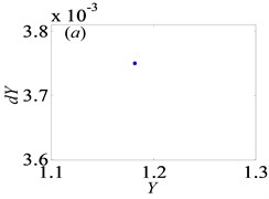
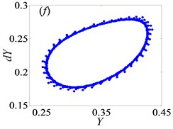
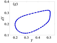
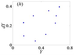
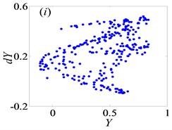
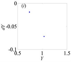
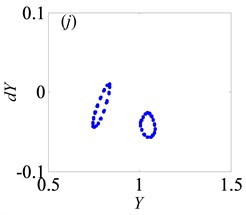
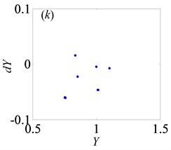
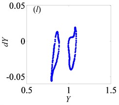
For the purpose of demonstrating the detailed transformational process concerning motion states of gear system with the change of , Poincaré maps of with respect to are applied to represent the dynamic characteristics of the gear pair system in Figs. 4(a)-(l). Then, Fig. 3 exhibits that the bifurcation diagram within the range of 0.5 0.7 is taken as an example to illustrate the bifurcation behavior of gear system at length. In Fig. 3, the period motion, namely period-one and period-two, can be observed at the low values of (i.e. 0.5 0.611), and the corresponding Poincaré maps are shown in Figs. 4(a)-(c). When increases from 0.612 to 0.624, the system goes into the quasi-periodic motion which describes as seen in Figs. 4(d)-(g). However, the system response turns from quasi-periodic motion to period doubling motion with the influence of stable attractor as shown in Fig. 4(h). Subsequently, the chaos occurs by the way of period doubling motion. Before entering into next state of chaos, there is a short Hopf bifurcation and period-three motion at 0.679 and 0.682, respectively. A similar evolution of motion is described with the increasing of meshing frequency in Ref. [1]. However, there are other motion states including quasi-periodic and Hopf motion in the gear pair system of Fig. 1 where more degrees-of-freedom are considered in this model.
Fig. 2Under lightly loaded condition, bifurcation diagrams of Ω with respect to Y when ξ is a) 0.03, b) 0.05, c) 0.07 and d) 0.09, respectively
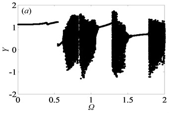
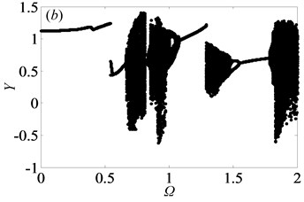
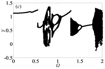
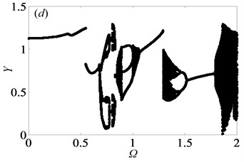
From the bifurcation diagrams in Fig. 2, it can be observed clearly that when 0.5, the gear system undergoes different motion states consisting of period doubling motion, quasi-periodic motion, Hopf bifurcation and chaos as increases. Importantly, the chaos occupies the main motion state in Figs. 2(a)-(b), which reveals that double-sided impact exists frequently in gear system when tooth pair keeps in mesh. In other words, the system may get into chaos easily, which would lead to predict and control the motion state of the system hard.
Fig. 3Under lightly loaded condition, partial enlarged drawing of bifurcation diagram with the range of 0.5 ≤Ω≤0.7 when ξ is 0.03
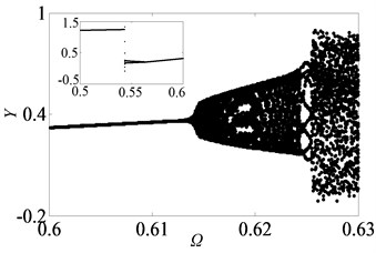
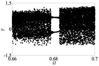
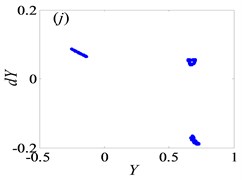
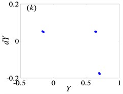
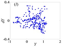
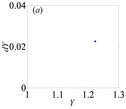
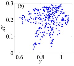
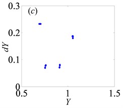
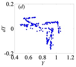
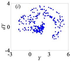
Fig. 4Under lightly loaded condition, Poincaré maps of Y with respect to dY at ξ= 0.03, when Ω is a) 0.45, b) 0.55, c) 0.6, d) 0.612, e) 0.613, f) 0.614, g) 0.618, h) 0.625, i) 0.627, j) 0.679, k) 0.682 and l) 0.686, respectively
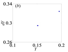
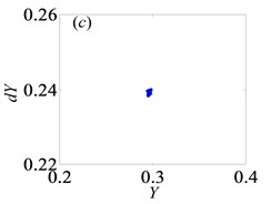
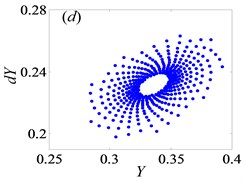
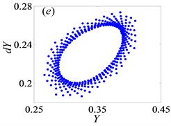
When 2, Fig. 5 shows the bifurcation diagrams of with respect to at different damping ratio values, keeping other parameters same with those under lightly loaded condition. Comparing bifurcation diagrams in Figs. 5(a)-(d), it is observed that the width of regions of chaos state becomes narrow gradually with the increasing of from 0.03 to 0.09, which is quite similar to that under lightly loaded condition. When the damping is equal to 0.09, the chaos is even completely replaced by periodic motion state. The phenomenon verifies the conclusion that increasing damping narrows the region of instability [8, 9, 23]. Due to large damping, higher energy is dissipated by the power transmission where the dynamic response and stability of system are improved.
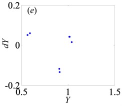
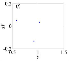
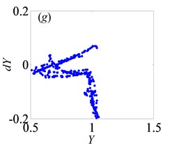
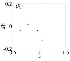
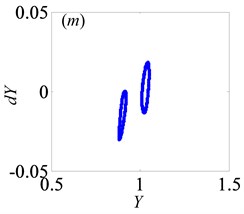
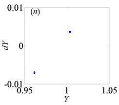
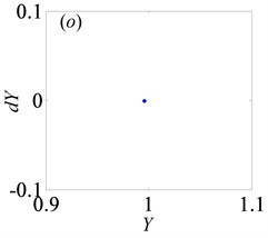
Similarly, the system goes into various types of motion state when 2. To research qualitatively the nonlinear dynamic behaviors of gear system under 2, it is essential to analyze bifurcation diagram with dimensionless meshing frequency varying, as shown in Fig. (6). Meanwhile, Fig. (7) shows the Poincaré maps of with respect to as changes from 0.65 to 0.95 at 0.03, which indicate the transitional process of motion states. From these above figures, the system enters into period-one state with the range of from 0.65 to 0.71, then changes to chaotic motion when increases to 0.715, as shown in Figs. 7(a)-(b), respectively. As reaches to 0.719, the system bifurcates from chaos to period doubling motion. After that it goes through chaotic motion again when 0.74 in Figs. 7(c)-(d). Subsequently, the system switches to period-six and period-three motions, then turns into chaos state via period doubling. After the width of region of chaotic motion, system bifurcates to period-four and period-two motion forms when increases to 0.774 and 0.79, respectively. Then, in the range of 0.81 0.89, the system frequently switches Hopf motion to period doubling motion, as shown in Figs. 7(j)-(n), respectively. After that, motion state of the system undergoes period-one state when 0.92. As a result, when meshing frequency varies, the system shows a diverse range of motion forms [2].
Fig. 5Under heavily loaded condition, bifurcation diagrams of Ω with respect to Y when ξ is a) 0.03, b) 0.05, c) 0.07 and d) 0.09, respectively
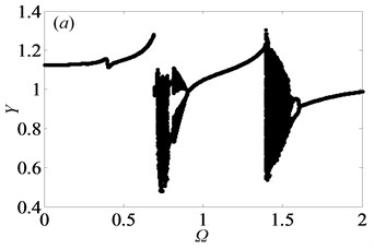
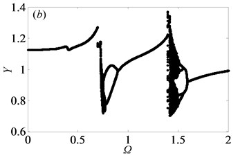
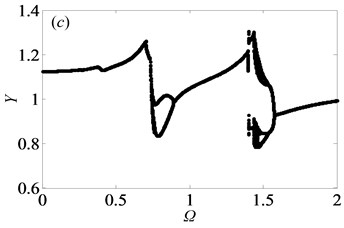
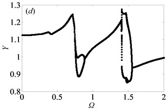
Comparing Fig. 2 and Fig. 5, it can be seen that the gear system is in the more stable state under heavily loaded condition than that under lightly loaded condition, which has been proved in Ref. [1]. To some extent, the main reason is that when the external load increases, the static meshing force will increase as well, triggering that double-sided and single-sided impact will disappear gradually to make gear pair meshing continuously. Meanwhile, it clearly shows that the system switches from chaos to period motion as illustrated in corresponding bifurcation diagrams. Furthermore, as damping ratio increases, the chaotic motion of system gradually transfers into quasi-periodic or period doubling motions. Through the above analysis of bifurcation features with changing under different loaded conditions, the motion states and the critical values can be obtained, which can apply to choose the reasonable rotational speed for keeping the stable motion state of gear system.
Fig. 6Under heavily loaded condition, partial enlarged drawing of bifurcation diagram with the range of 0.65 ≤Ω≤ 0.95 when ξ is 0.03
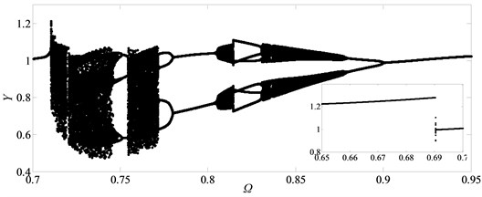
Fig. 7Under heavily loaded condition, Poincaré maps of Y with respect to dY at ξ= 0.03, when Ω is a) 0.65, b) 0.715, c) 0.719, d) 0.740, e) 0.749, f) 0.752, g) 0.76, h) 0.774, i) 0.79, j) 0.81, k) 0.82, l) 0.832, m) 0.86, n) 0.89 and o) 0.92, respectively
3.2. Bifurcation and chaos analysis of the effect of dimensionless gear backlash
Owing to some objective factors, namely manufacturing accuracy, installation error, gear lubrication and so on, gear backlash always exists, which shows strong nonlinear feature and has a great influence on the durability and stability of gear system [17]. Therefore, it is vital to analyze the nonlinear behaviors of gear system caused by gear backlash. Keeping other system parameters constant, the gear backlash B is assigned as control parameter.
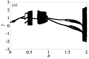
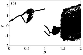
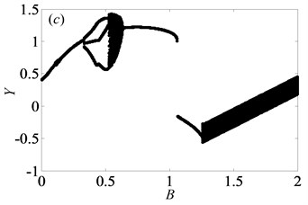
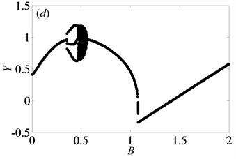
When 0.5, the bifurcation diagrams with the change of dimensionless gear backlash are shown in Fig. 8. Under lightly loaded condition, as damping ratio reaches to 0.03, 0.05, 0.07 and 0.09 respectively, Fig. 8 suggests the different bifurcation characteristics of the gear system. When increases from 0 to 1, the system enters into chaotic state by the way of period-three motion and then transfers frequently between chaos and period doubling motion as shown in Figs. 8(a)-(b). However, it could be shown from Figs. 8(c)-(d) that the system response starts with period-three, then undergoes chaos, finally bifurcates to period-one within the range of 0 1. When continues to increase, the system goes into chaos again by the channel of period doubling or period-one motion as seen in Figs. 8(a)-(c), while it will always be under period-one motion in Fig. 8(d). As 0.11, the system motion only includes period-three and period-one motions. A similar process of bifurcation with different damping ratio can be found in Ref. [22]. As increases, the width of window of chaotic motion becomes narrower gradually and the system enters into the second part of regions of chaotic motion much earlier. However, the overall area of chaotic region is gradually reduced, especially in the longitudinal direction. When is equal to 0.11, the second part of chaotic region disappears, which is replaced by period-one motion. Additionally, the amplitude of vibration displacement decreases gradually as increases, which is revealed from Ref. [1] as well.
Fig. 8Under lightly loaded condition, bifurcation diagrams of B with respect to Y when ξ is a) 0.03, b) 0.05, c) 0.07 and d) 0.09, respectively
In order to further explain the change process of motion states of gear system, partial enlarged drawing of bifurcation diagram and the corresponding Poincaré maps are shown in Figs. 9-10 respectively, when is in the range from 0.05 to 0.65 and is 0.03. From Fig. 9, it clearly shows that the system goes into complex motion states, involving period doubling motion, quasi-periodic motion, Hopf bifurcation motion as well as chaos. When 0.05, the system is in the period-one motion as exhibited in Fig. 10(a), which reveals that the system is under the stable state. Due to small value of gear backlash, gears keep meshing so that the system always undergoes the stable period-one motion state. Then, the system bifurcates to period-two motion as increases to 0.075.
Fig. 9Under lightly loaded condition, partial enlarged drawing of bifurcation diagram with the range of 0.05 ≤B≤ 0.65 when ξ is 0.03
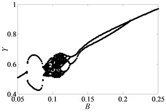
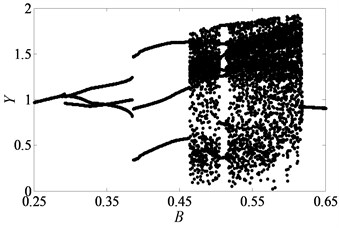
Fig. 10Under lightly loaded condition, Poincaré maps of Y with respect to dY at ξ= 0.03, when B is a) 0.05, b) 0.075, c) 0.09, d) 0.097, e) 0.103, f) 0.118, g) 0.122, h) 0.14, i) 0.35, j) 0.48, k) 0.5145, l) 0.54, respectively
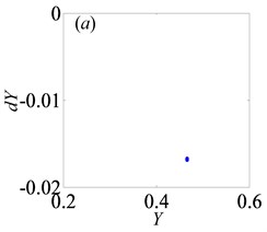
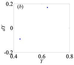
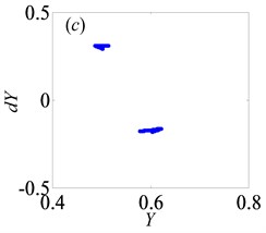
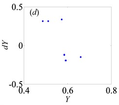
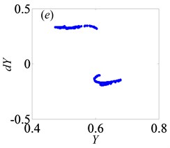
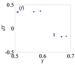
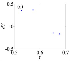
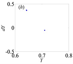
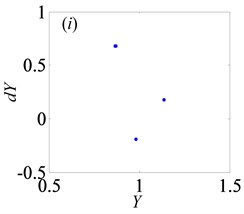
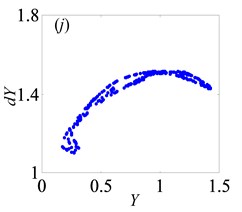
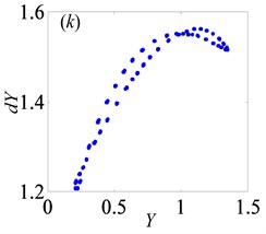
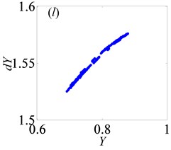
Later, the system goes into the complex states which converts frequently between chaos and period doubling motion, when changes from 0.087 to 0.118, as can be seen from Figs. 10(c)-(f). Then, the system bifurcates inversely from period-eight to period-four and even period-two, as reaches to 0.122 and 0.14, which demonstrate from Figs. 10(g)-(h), respectively. However, the system gets into period-three motion by the way of crisis from period-two motion in Fig. 10(i) when 0.35. As continues to increase, the system switches to chaos, then changes to quasi-periodic motion, finally transfer into chaos again, as shown in Figs. 10(j)-(l).
Based on the above analysis, the dimensionless gear backlash varying leads to complex bifurcation properties, which can be employed to illustrate the nonlinear dynamic characteristics of gear system. When is 0.5 and is less than or equal to 0.05, the gear system presents the states of periodic motion and chaotic motion alternately with the increase of . However, when is larger than a certain value, the system enters into the continuous chaotic motion, as seen in Figs. 8(a)-(b). Likewise, it is of significance to analyze the bifurcation features under heavily loaded condition to compare those under lightly loaded condition. Hence, the system parameters are selected as same as those under lightly loaded condition. Then, the bifurcation diagram with the change of is obtained as seen in Fig. 11.
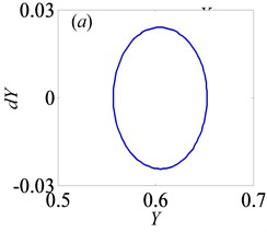
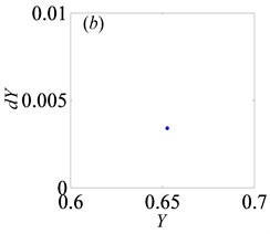
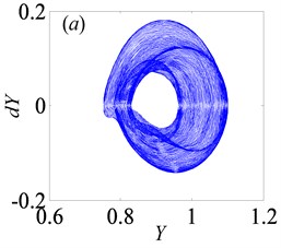
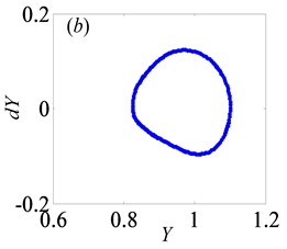
In Fig. 11, as increases from 0 to 2, the system keeps under period-one motion, and the corresponding phase portrait and Poincaré map are shown in Fig. 12, when 0.5. In other words, gear backlash varying only changes the vibration amplitude of gear system while it doesn’t affect the system motion property. This is in line with the numerical analysis results of a spur gear pair system with three DOF described in Ref. [24].
By comparing Fig. 8 and Fig. 12, it can be seen that the influences of loaded condition, damping ratio and dimensionless gear backlash on the bifurcation characteristics of gear system are analyzed systematically. Under lightly loaded condition, the system has more complex bifurcation features than those under heavily loaded condition. Furthermore, under different damping ratios, there are significant differences among the bifurcation diagrams of with respect to . As increases, the system tends to enter into the stable period motion state. Hence, these analysis results can provide theoretical basis for selecting appropriate gear backlash to avoid the chaos and ensure the system under the stable motion state.
Fig. 11Under heavily loaded condition, bifurcation diagrams of B with respect to Y
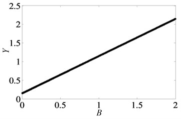
Fig. 12Under heavily loaded condition, phase portrait and Poincaré maps of Y with respect to dY when B= 0.5
3.3. Bifurcation and chaos analysis of the effect of dimensionless bearing clearance
Bearing clearance is also one of key parameters that affect the dynamic behavior of gear transmission system. Therefore, it is crucial to analyze the influence of bearing clearance on nonlinear dynamic characteristic of system. Then, keeping other parameters constant, the bifurcation diagrams with dimensionless bearing clearance ( 1, 2) changing are obtained when 0.5 or 2, as shown in Fig. 13 and Fig. 15, respectively.
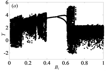
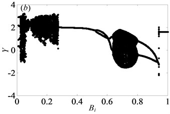
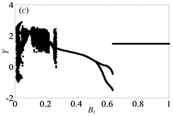
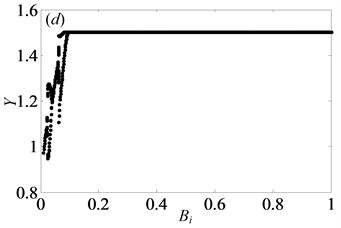
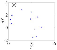
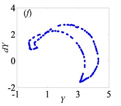
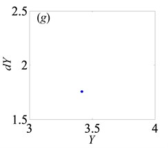
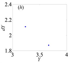
In Fig. 13, when 0.5, the system shows complex forms of motion states with the change of and different . From Fig. 13(a), it clearly indicates that the chaos is the main motion within the range of 0 1, but in the meantime, there are other motion types, namely period doubling and quasi-periodic motions. When 0.29, the system enters into the chaos, as shown in Fig. 14(a). Then, it turns into quasi-periodic motion as seen in Figs. 14(b)-(c), when reaches to 0.29 and 0.302, respectively. Later, the system goes into chaos again by the channel of quasi-periodic motion, as seen in Fig. 14(d). When keeps increasing to 0.363, the system bifurcates to period doubling motion which exists in a very narrow motion window. Subsequently, when 0.377, the system changes to quasi-periodic motion again, as shown in Fig. 14(f). Finally, the system undergoes the chaos through the route of period-two state as seen in Figs. 14(h)-(i).
From Figs. 13(a)-(d), it clearly shows that as increases, the width of regions of chaos becomes narrow and the amplitude of displacement decreases gradually. In other words, when increases from 0.03 to 0.09, the system becomes stable increasingly. Over the range of 0.27, the system is always under the period motion including period-one and period-two motion at 0.07. Furthermore, within the range of 0.636 1, the vibration amplitude of the gear system keeps certain constant. Likewise, under 0.09, the system is in the period motion state, which switches between period-one and period-two motions with the range of 0.094 and always stays under the period-one state when 0.094 1. In addition, the system occurs crisis phenomenon in Fig. 13(b, c), which are consistent with the conclusion obtained in Ref. [7].
Fig. 13Under lightly loaded condition, bifurcation diagrams of Bi with respect to Y when ξ is a) 0.03, b) 0.05, c) 0.07 and d) 0.09, respectively
When 2, the system is only in quasi-periodic motion state and the amplitude along the line of action keeps certain constant in the range of 0 1, as shown in Fig. 15. For instance, when is chosen to 0.5, the phase portrait and Poincaré map are obtained in Fig. 16, which illustrate the system enters into quasi-periodic motion. It means that bearing clearance affects weakly on motion characteristics of gear system under heavily loaded condition.
Fig. 14Under lightly loaded condition, Poincaré maps of Y with respect to dY at ξ= 0.03, when Bi is a) 0.1, b) 0.29, c) 0.302, d) 0.34, e) 0.363, f) 0.377, g) 0.45, h) 0.55, and i) 0.634, respectively
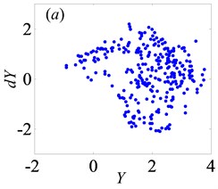
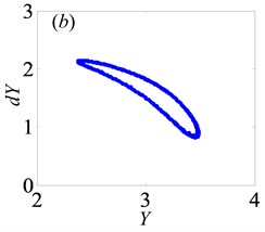
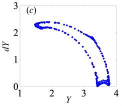
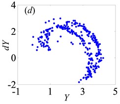
According to the analysis about the effect of dimensionless bearing clearance on bifurcation and chaos, it could be obtained that has considerable impact on bifurcation property under lightly loaded condition, which leads to different and complex types of motion states. Hence, it is essential to choose suitable bearing clearance for ensuring the stability of gear transmission and reducing the vibration intensity of the gear system.
Fig. 15Under heavily loaded condition, bifurcation diagrams of Bi versus Y
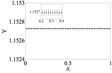
Fig. 16Under heavily loaded condition, phase portrait and Poincaré maps of Y with respect to dY when Bi= 0.5
4. Conclusions
This study establishes a three-DOF nonlinear dynamic model of a spur gear pair system, considering transmission error, gear backlash, bearing clearance, time-varying meshing stiffness, torque fluctuation and external radial preload. Through introducing the relative torsional displacement as a new DOF, the dynamics of system can be investigated by using Runge-Kutta integration method. The features of bifurcation and chaos of the gear system with respect to control parameters involving meshing frequency, gear backlash, bearing clearance, damping ratio and force ratio are discussed in detail. The analysis results can not only provide a better understanding of bifurcation characteristics, but also ensure appropriate values of system key parameters to avoid the chaos, reduce impact and extend service life of gear system. The detailed conclusions are listed as follows:
1) As dimensionless meshing frequency increases, the gear system shows multiple motion states, such as period doubling motion, quasi-periodic motion, Hopf bifurcation as well as chaotic motion. According to the bifurcation diagrams, the meshing frequency should be chosen appropriately to keep system stable.
2) Gear backlash has significant influences on bifurcation properties and chaos of gear system. Under lightly loaded condition, the system undergoes various types of motion states with the change of dimensionless gear backlash, while it only is in period-one motion state under heavily loaded condition.
3) Similarly, the bifurcation features with bearing clearance as control factor present enormous difference when gear system is under different loaded conditions. Under the lightly loaded condition, the system response switches from chaotic motion to period doubling or quasi-periodic state. However, under heavily loaded condition, the bearing clearance has a weak effect on dynamic behavior of gear system.
4) It can be observed that under heavily loaded condition, the system tends to be more stable by comparing that under lightly loaded condition. Due to the absence of single-sided and double-sided impact when external load increases, the gears keep meshing which makes gear system run stably.
5) When damping ratio increases, the window width of chaotic motion becomes gradually narrow and the vibration amplitude along the line of action decreases. In other words, the damping ratio can hinder effectively the chaotic motion in the gear transmission system.
There are several aspects that should be investigated further, although we have obtained the bifurcation characteristics with respect to different control parameters under different loaded conditions. In the next stage, we will carry out stability analysis for the gear pair system, study the effects of tooth surface friction on the dynamic response and analyze the non-smooth dynamic behavior with gear backlash.
References
-
Kahraman A., Singh R. Non-linear dynamics of a spur gear pair. Journal of Sound and Vibration, Vol. 142, Issue 1, 1990, p. 49-75.
-
Kahraman A., Singh R. Non-linear dynamics of a geared rotor-bearing system with multiple clearances. Journal of Sound and Vibration, Vol. 144, Issue 3, 1991, p. 469-506.
-
Kahraman A., Singh R. Interactions between time-varying mesh stiffness and clearance non-linearities in a geared system. Journal of Sound and Vibration, Vol. 146, Issue 1, 1991, p. 135-156.
-
Raghothama A., Narayanan S. Bifurcation and chaos in geared rotor bearing system by incremental harmonic balance method. Journal of Sound and Vibration, Vol. 226, Issue 3, 1999, p. 469-492.
-
Theodossiades S., Natsiavas S. Non-linear dynamics of gear pair systems with periodic stiffness and backlash. Journal of Sound and Vibration, Vol. 229, Issue 2, 2000, p. 287-310.
-
Litak G., Friswell M.I. Vibrations in gear systems. Chaos, Solitons and Fractals, Vol. 16, Issue 5, 2003, p. 795-800.
-
Wang S. M., Shen Y. W., Yuan R. Bifurcation and chaos in a nonlinear dynamic system with multiple clearances and time-varying stiffness. Journal of Northwestern Polytechnical University, Vol. 21, Issue 2, 2003, p. 191-194, (in Chinese).
-
Al-Shyyab A., Kahraman A. Non-linear dynamic analysis of a multi-mesh gear train using multi-term harmonic balance method: period-one motions. Journal of Sound and Vibration, Vol. 284, 2005, p. 151-172.
-
Al-Shyyab A., Kahraman A. Non-linear dynamic analysis of a multi-mesh gear train using multi-term harmonic balance method: sub-harmonic motions. Journal of Sound and Vibration, Vol. 279, 2005, p. 417-451.
-
Shen Y. J., Yang S. P., Liu X. D. Nonlinear dynamics of a spur gear pair with time-varying stiffness and backlash based on incremental harmonic balance method. International Journal of Mechanical Sciences, Vol. 48, Issue 11, 2006, p. 1256-1263.
-
Walha L., Fakhfakh T., Haddar M. Backlash effect on dynamic analysis of a two-stage spur gear system. Journal of Failure Analysis and Prevention, Vol. 6, Issue 3, 2006, p. 60-68.
-
Chang Jian C.-W. Strong nonlinearity analysis for gear bearing system under nonlinear suspension-bifurcation and chaos. Nonlinear Analysis: Real World Applications, Vol. 6, Issue 3, 2010, p. 1760-1774.
-
Chang Jian C.-W., Chang S. M. Bifurcation and chaos analysis of spur gear pair with and without nonlinear suspension. Nonlinear Analysis: Real World Applications, Vol. 12, Issue 2, 2011, p. 979-989.
-
Chen S. Y., Tang J. Y., Luo C. W., et al. Nonlinear dynamic characteristics of geared rotor bearing systems with dynamic backlash and friction. Mechanism and Machine Theory, Vol. 46, Issue 4, 2011, p. 466-478.
-
Moradi H., Salarieh H. Analysis of nonlinear oscillations in spur gear pairs with approximated modelling of backlash nonlinearity. Mechanism and Machine Theory, Vol. 51, Issue 5, 2012, p. 14-31.
-
Farshidianfar A., Saghafi A. Global bifurcation and chaos analysis in nonlinear vibration of spur gear systems. Nonlinear Dynamics, Vol. 75, 2014, p. 783-806.
-
Liu J., Wang S. J., Zhou S. H., et al. Nonlinear behavior of a spur gear pair transmission system with backlash. Journal of Vibroengineering, Vol. 16, Issue 8, 2014, p. 3922-3938.
-
Gou X. F., Lv X. H., Chen D. L. Research on Hopf bifurcation and chaos of the single-stage gear transmission system. China Mechanical Engineering, Vol. 25, Issue 5, 2014, p. 649-683, (in Chinese).
-
Gou X. F., Zhu L. Y., Chen D. L. Bifurcation and chaos analysis of spur gear pair in two-parameter plane. Nonlinear Dynamics, Vol. 79, Issue 3, 2015, p. 2225-2235.
-
Liu Z. X., Liu Z. S., Zhao J. M., et al. Study on interactions between tooth backlash and journal bearing clearance nonlinearity in spur gear pair system. Mechanism and Machine Theory, Vol. 107, 2017, p. 229-245.
-
Sheng D. P., Zhu R. P., Jin G. H., et al. Dynamic load sharing behavior of transverse-torsional coupled planetary gear train with multiple clearances. Journal of Central South University, Vol. 22, 2015, p. 2521-2532.
-
Zhu R. P., Sheng D. P., Lu F. X., et al. Modeling and bifurcation characteristics of double stage planetary gear train with multiple clearances. ASME International Design Engineering Technical Conferences and Computers and Information in Engineering Conference, Boston, Vol. 10, 2015, p. 1-12.
-
Lin J., Parker R. G. Mesh stiffness vibration instabilities in two-stage gear systems. Journal of Vibration and Acoustics, Vol. 124, Issue 1, 2002, p. 68-76.
-
Xu S., Zeng F. L., Zhang S. L. Dynamic response analysis of transmission gear system with backlash. Agricultural Equipment and Vehicle Engineering, Vol. 51, 2013, p. 1-4, (in Chinese).
Cited by
About this article
This work was supported by the National Natural Science Foundation of China (Grant No. 51575320).
