Abstract
With the speeding up of high-speed trains, the radiation noise generated from plates of the vehicle body was becoming increasingly obvious; however, fewer researches were performed on this aspect at present. The dynamic equation of the head vehicle of the high-speed train and the vehicle-track coupled dynamic model were both established, and then the dynamic load excitation of the vehicle body on uneven tracks was eventually obtained. With the material properties attributed, the finite element model of the vehicle body was eventually obtained to solve the modal, which was subsequently compared with the experimental one to verify the accuracy of the model. Based on the structural-acoustic coupling boundary element method, the noise distribution inside the passenger compartment of the high-speed train was calculated. Moreover, with the employment of the acoustic transfer vector (ATV) technology, the contribution coefficients of each plate of the vehicle body to the maximum sound pressure point were calculated. It was shown through the result that when the sound-absorbing materials inside the vehicle were ignored at the speed of 300 km/h, the sound pressure level inside the high-speed train ranged between 80 dB and 93 dB. Furthermore, when transverse ribs were added to the passenger compartment floor, its contribution coefficient to the sound pressure at the field points could be reduced, thus the noise inside the high-speed train could be improved.
1. Introduction
With the rapid development of high-speed railways, when high speed and high security have been pursued, ride comfort has also been increasingly emphasized [1]. Nevertheless, interior noise will affect the comfort of passengers, which will meanwhile tend to bring the driver into irritable mood, thus threaten the safety [2]; consequently, interior noise reduction has become an urgent problem to be solved.
The noises inside the passenger compartment during the train operation are generally composed of the external noise transmitted through the vehicle-body plates and that produced by the vibration of the compartment itself, wherein the latter is principally generated by the resonance of the vehicle-body plates resulted from the bogie vibration [3]. In reference [4], based on the wheel-rail noise mechanism of high-speed railways, the wheel-rail noise analysis model of high-speed railways was established to research into the wheel-rail rolling noise. Compared with the vibration noise resulted from the resonance of the vehicle-body plates by the bogie vibration, both of them are caused by the rail unevenness; however, relative to the interior noise, the vibration noise by the bogie belongs to the structural noise, mainly in low frequency; while the wheel-rail rolling noise belongs to the transmission noise, mainly in medium and low frequency. And in reference [5], the flow field finite element model of the train head was built up, wherein with the three-dimensional large eddy simulation method employed, the aerodynamic noise induced by the high-speed train head was predicted through the Lighthill-Curle acoustic analogy theory. Nevertheless, fewer researches have been conducted on the vibration radiation noise of the vehicle-body plates of the high-speed train at present. When the train runs at high speed, vibrations of the bogie will be generated in three directions due to rail unevenness, wherein the vibration loads will act at the junctions between the bogie and the vehicle body, which will consequently result in the plate vibrations, hence the radiation noise. Overall, it proves significantly important to research on the vibration radiation noise of the vehicle-body plates for the interior noise reduction.
2. Dynamic equation of the head vehicle of the high-speed train
Take the inertial system as the reference system, and get the unit vector to be align with the body-fitted coordinate, wherein →eix, →eiy, →eiz represent the rigid body displacements respectively, and then the displacement vector of the free bodycould be expressed as [6]:
where rix/I, riy/I and riz/I represent the unit vectors in x, y and z directions respectively. The displacement of a single free body could be defined on the basis of six degrees of freedom, i.e.:
wherein α, β and γ are the rotating angles of the free body around the coordinate axles, respectively.
A system composed of x rigid bodies and a complete ring could be denoted by the second Lagrange equation as:
wherein T is the kinetic energy of the multi-body system of x rigid bodies, and:
where ν represent speed, m represents mass, ω represents angular speed and I represents rotational inertia. The vector ρ of the generalized force could be denoted as the following equation by the apply force and moment of each rigid body:
From the equation above, the motion equation of the multi-body system could be obtained:
Through the motion equation obtained by Eq. (6), the multi-body dynamics software was employed to calculate the vertical acting force on the vehicle body by the bogie on uneven rails, which was then applied on the vehicle body to analyze the low-frequency noise inside the high-speed trains.
3. Train-rail coupled dynamic model
The head vehicle of the high-speed train is a complicated multi-body vibration system, which is mainly constituted by the vehicle body, the bogie, the wheel set and the axle box, etc. Therefore, some elements are necessary to be simplified during the train modeling to simulate the excitation produced by the train on uneven rails.
Fig. 1The train-rail coupled dynamic model
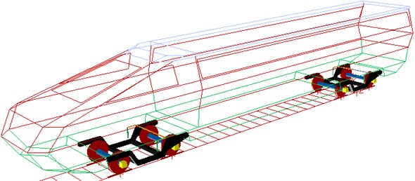
With the specialized multi-body dynamics software SIMPACK and the sub-structuring and parametric modeling method employed, the rigid models of the bogie, the wheel set, the axle box and the vehicle body, etc. were established, wherein the corresponding mass and rotational inertia were attributed respectively. Moreover, the connection type between each component was simulated by the hinged type. Furthermore, the spring, the shock absorber and other elastic elements were simulated by the force element, with the rigidity and damp attributed. And the train-rail coupled dynamic model was shown in Fig. 1.
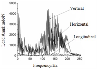
Fig. 2The load amplitudes of each contact point at 300 km/h
a) Point A
b) Point B
c) Point C
d) Point D
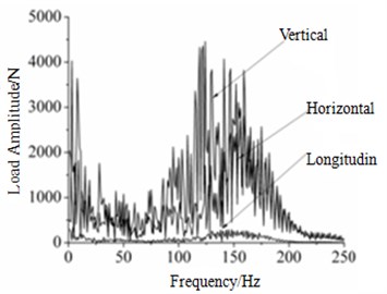
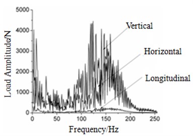
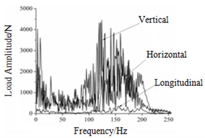
The bogie close to the head was defined as Bogie 1, and the one close to the end as Bogie 2, besides, the contact points between the under frame and the secondary air springs on the left and the right of Bogie 1 were defined as Contact point A and B, respectively, while those of Bogie 2 as Contact point C and D, respectively. The excitation generated by the high-speed train on uneven rails was calculated by offline integral with the running speed of 300 km/h. American railway lines are divided into 6 levels according to ride performance. The higher the level number is, the better the ride performance will be. This paper is written based on high-speed railway projects in China. Researches show that the harshness of China’s three major trunk lines is identical to American fifth line spectrum; there is no specialized railway spectrum which can be imported to simulation software for computation in China. Therefore, American fifth line spectrum is adopted in multi-body dynamics computation.
The load amplitudes of each contact point mainly ranged between 0 and 250 Hz [7], which was therefore treated as the calculated frequency so as to improve the calculation speed, with the result shown in Fig. 2. It could be obtained from the figure that the maximum load amplitude (4500 N) of all the contact points occurred at 120 Hz or so, which decreased with the increasing frequency. Among the loads in three directions that each contact point suffered, those in the vertical and the horizontal directions proved much larger than that in the longitudinal direction, and the vertical one was larger than the horizontal one. Consequently, it could be concluded that the vertical exciting load was the main contributor to the plate vibration of the vehicle body, and the interior noise could be reduced if the load excitation that the vehicle body suffers on uneven rails is reduced.
4. Head-vehicle modal analysis of the high-speed train
The head-vehicle body of the high-speed train, which is principally composed of the switching mechanism, the driver’s cab and the passenger compartment, is complicatedly structured with stream-line head. Concretely, the car body, with hollow extruded sections covered as a whole, is constituted by the underframe, the side walls and the roof, wherein the underframe is made up of the floor, the side girder, the sleeper beam, the traction beam and the buffer beam; besides, the floor, the side girder, the roof and the side wall are all welded by hollow extruded sections with enough rigidity, i.e. the aluminum alloy 6N01 with favorable extruding property and welding performance, and the end wall was assembled and welded by aluminum alloy sections and plates of 5083 series.
Fig. 3The finite element model of the high-speed train
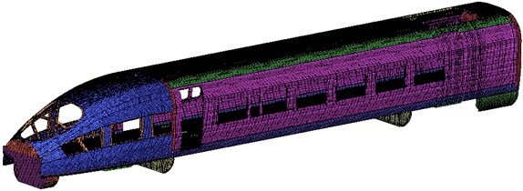
For the head-vehicle finite element model, the unnecessary elements, such as chamfers and bolted holes, etc., were ignored in order to save the calculation time. Concretely, finer meshes were adopted for the key analysis part and sparser ones for the others, thus the mesh quantity could be decreased and the calculation speed improved. The vehicle body plates were meshed by shell elements, wherein for high accuracy, besides a few triangles at the structural changes and connections, quadrilaterals accounted for the most, and the finite element model was shown in Fig. 3, with the mesh number of 425577, and the node number of 352880, most of the elements are quadrilateral elements, with triangular elements at some positions. Besides, the plate density was defined as ρ=2686 kg/m3, the elastic modulus as E= 72.4 GPa and the Poisson ratio μ=0.3.
The elastic vibration of the vehicle body is sensitive to the surface abrasion of the wheel, and in order to avoid resonance, the first-order vertical bending vibration frequency is required to be above 15 Hz. Thus, the first 6 orders of the overall modals for the vehicle body were tested, as shown in Table 1:
Table 1The first 6 orders of the overall modals for the high-speed train
Order | Frequency / Hz | Vibration mode |
1 | 15.43 | Body section diamonding |
2 | 18.36 | The first order vertical bending (whole vehicle) |
3 | 21.74 | The first order twisting |
4 | 22.83 | The first order vertical one (roof and underframe) |
5 | 25.12 | The first order twisting + horizontal bending |
6 | 26.95 | The second order vertical one (underframe) |
Table 2Comparisons between the test and the simulation modals
Order | Test modal / Hz | Simulation modal / Hz | Error / % |
1 | 15.43 | 16.11 | 4.4 |
2 | 18.36 | 17.79 | –3.1 |
3 | 21.74 | 21.98 | 1.1 |
4 | 22.83 | 23.46 | 2.8 |
5 | 25.12 | 24.86 | –1.0 |
6 | 26.95 | 27.75 | 3.0 |
It could be seen from the Table 1 above that the first order vertical bending vibration frequency was 18.36 Hz, much larger than 15 Hz, so the vertical bending vibration frequency of the vehicle body met the requirement; while the twisting frequency of the vehicle body was relatively high, which indicted a larger torsional stiffness of the vehicle body.
The solid model was relatively complex, and so as to verify the accuracy of the finite element model in Fig. 3, the first 6 orders of modals were numerically calculated, which were than compared with the test results, as shown in Table 2. The modal shapes in the first 6 order simulation results are as Fig. 4.
Fig. 4The modal shapes in the first 6 order simulation results

(1) 16.11Hz

(2) 17.79

(3) 21.98

(4) 23.46

(5) 24.86

(6) 27.75
It could be seen from Table 2 that the relative error between the simulation and the test values was controlled within the engineering permissible range of 5 %, consequently, the finite element model proved to be reliable and could be employed for the subsequent acoustic analysis.
5. Noise and contribution degree analysis in the passenger compartment
5.1. Head-vehicle boundary element model of high-speed train
The meshes of the internal vehicle-body surface were adopted as the boundary element meshes of the head vehicle, with the mesh sizes re-adjusted. To save the computing time, the boundary element meshes shall be as few as possible. Also, the edge length of the maximum unit of the boundary element meshes shall be less than 1/6 of the shortest wavelength of the calculation frequency. Furthermore, the fluid property inside the vehicle body was defined as air, with the density of 1.225 kg/m3, and the sound speed of 340 m/s. To calculate the contribution coefficient of the vehicle-body plates, the boundary element meshes were divided into 14 panels, as shown in Fig. 5, and the names and numbers of the panels were shown in Table 3.
Fig. 5The acoustic boundary element model and the panel distribution of the train

Table 3Names and numbers of each panels of the head car
Panel number | Location | Panel number | Location |
1 | Right-side plate of the passenger compartment | 8 | Left-side plate of the passenger compartment |
2 | Right-side plate of the passenger compartment | 9 | Left-side plate of the passenger compartment |
3 | Right-side plate of the passenger compartment | 10 | The driver’s cab floor |
4 | Roof of the passenger compartment | 11 | Left-side plate of the driver’s cab |
5 | Roof of the passenger compartment | 12 | Right-side plate of the driver’s cab |
6 | Rear end plate of the passenger compartment | 13 | Driver’s cab roof |
7 | Left-side plate of the passenger compartment | 14 | Front end plate of the driver’s cab |
5.2. Noise analysis and calculation inside the passenger compartment
The so-called structural-acoustic coupling method is that the motion equation of the structure system and the integration equation of the sound field radiation are related together by the coupling coefficient matrix. The dynamic characteristic of the structure is generally denoted by the intrinsic modal, and this concept also applies to the structural-acoustic coupling system, whose matrix equation in the physical coordinates could be denoted as [8, 9]:
wherein [M] is the mass matrix, [C] is the structural damping matrix, [K] is the structural stiffness matrix, {u} is the displacement of the structure under the physical coordinates, [CAD] and [CDA] are coupling matrixes, {Fa} is the acoustic load, {Fd} is the mechanical load applied on the structure, [A] is a symmetric matrix, and ω is the circular frequency of vibration, ω=2πf.
According to the interior noise measurement standard (ISO3381) for rail vehicles, field point meshes were established in the passenger compartment at 1.2 m from the floor, wherein 40 field points were evenly taken along the centerline of the passenger compartment.
The vertical load obtained through the SIMPACK software for the multi-body dynamics was applied on the vehicle-body finite element model, and the frequency response function of the vehicle body was calculated by ABAQUS finite element software, thus the surface vibration speed of the vehicle body was eventually obtained. The finite element meshes, the boundary element meshes and the field point meshes of the vehicle body were imported into the Virtual.Lab acoustic simulation software, respectively, and with the boundary element method employed, the structural-acoustic coupling model was built up to calculate the noise inside the passenger compartment. For the surface vibration velocity of the body was exhibited on the structural meshes, the vibration acceleration on the structural meshes is required to be mapped to the boundary element meshes during calculation, in this way, the radiation sound field of the body vibration could be calculated out, wherein the calculated frequency ranged from 0 to 250 Hz.
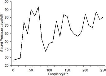
The sound pressure levels of the first to the 40th field points were calculated, respectively, and through comparisons, it was found that the sound pressure levels of each field points ranged between 80 and 93 dB at the speed of 300 km/h, with the maximum at the 39th field point, whose sound pressure level was shown in Fig. 6, wherein the maximum noise appeared as 93 dB at 70 Hz. There are various kinds of sound-absorbing materials inside the high-speed trains, the seats for example, which could reduce the noise. During the calculation of the vibration radiated noise of the vehicle body plates, the sound-absorbing effect was not taken into consideration, so the results would be larger than the actual ones.
Fig. 6Sound pressure level of the field points
5.3. Contribution coefficient analysis of the head-vehicle plates of the high-speed trains
The panel is a set of unit in the acoustic boundary element model, while the panel P’s sound pressure contribution towards one single point in the interior sound field is the sum of the contribution of all the cells included in the panel, as follows:
In this equation, Pe,i(ω) is the sound pressure contribution of unit i. Pc is the contribution of panel P; Np is the total number of units in panel P:
Therefore, before starting the panel contribution analysis, it is very necessary to know the definition of ATVi(ω), νe,i(ω) (unit vibration velocity in the acoustic BEM model) and the panel. The physical meaning of ATV can be understood as the sound pressure at certain field point caused by unit speed or node speed at a specific frequency, which can be directly solved by simulation. Besides, the unit vibration velocity in the acoustic BEM model can be obtained directly in calculation.
The sound pressure at a certain point in the sound field could be related to the vibration speed of the model meshes through the acoustic transfer vector, and based on it, the contribution coefficients of each plate to a certain point could be calculated.
With the employment of the acoustic simulation software, the simulation analysis of the contribution coefficient was conducted. And through the ATV technology, the contributions of each panels at 70 Hz to the 39th field point at the speed of 300 km/h were obtained, which were then normalized to obtain the acoustic contribution coefficient of the panels, as shown in Fig. 7.
Fig. 7Contribution coefficients of the panels
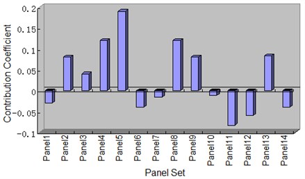
The floor of the passenger compartment 8 exhibited the maximum contribution coefficient to the 39th field point, i.e. 0.19, followed by the roof 4 and left-side plate 8 of the passenger compartment. While the left-side plate 11 and the right-side plate 12 of the driver’s cab exhibited negative contributions to the 39th field point and structure changes of both the two panels will increase the sound pressure of this field point.
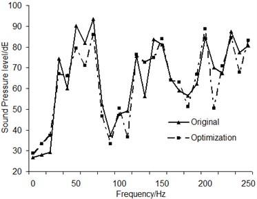
Through adding ribs to the plate, its stiffness property could be improved, so that the resonance frequency is possible to be avoided, and its vibration radiated noise could be reduced. It could be concluded from the contribution analysis that the sound pressure at the 39th field point could be reduced if the contribution degree from the roof of the passenger compartment is reduced. On the floor of the passenger compartment, three transverse ribs with length of 1m and thickness of 1.5 mm were welded, with the spacing of 2 m. By comparison analysis, the sound pressure level at the field point was reduced by 7 dB at 70 Hz after optimization, as shown in Fig. 8. Thus, variations of the plate structure could effectively decrease the radiated noise of the plates.
Fig. 8Sound pressure level comparisons before and after optimization
6. Conclusions
1) During the operation of the high-speed train, among the excitations on the vehicle body generated by the bogie on uneven rails, the vertical and the horizontal loads proved much larger than the longitudinal one, and the vertical one was larger than the horizontal one. Besides, the load excitations mainly concentrated in the low frequency band.
2) Through comparisons between the simulation and experimental modals, the error was proved within the permissible range, thus the reliability of the simulation model was verified, which could be employed for the subsequent acoustic analysis.
3) When the train operation speed was 300 km/h, with the sound-absorbing materials inside the vehicle ignored, the A sound pressure level inside the vehicle varied between 80 and 93 dB, and the maximum of the field point was 93 dB.
4) Through adding transverse ribs to the floor of the passenger compartment, the overall stiffness performance of the plate could be changed and vibration radiated noise of the plate could be reduced.
References
-
Zhang Shu-Guang The system optimization study of Beijing-Shanghai high-speed railway. Beijin, China Railway Publishing House, 2009, p. 74.
-
Lamancusa J. S. Numerical optimization techniques for structural-acoustic design of rectangular panels. Computer and Structures, Vol. 48, Issue 4, 1993, p. 661-675.
-
Miao Xin-Fang Analysis and control of High-speed train Interior noise. Chemical Engineering and Equipment, 2010, p. 202.
-
Xu Zhi-Sheng, Zhai Yuan-Ming Prediction and analysis High-speed railway wheel-rail noise. China Railway Science, Vol. 39, 2004, p. 20-25.
-
Xiao You-Gang, Kang Zhi-Cheng Numerical prediction of aerodynamic noise radiated from high-speed train head surf. Journal of Central South University, Science and Technology, 2008, p. 1269-1271.
-
Miu Bing-Rong Simpack kinetic analysis basic tutorial. Southwest Jiaotong University Press, 2008, p. 26-32.
-
Xiao You-Gang, Kang Zhi-Cheng Contribution analysis of Wheel-rail high-speed train passenger compartment noise excitation. Journal of South China University of Technology, Natural Science Edition, 2009, p. 99-100.
-
Serbert A. F., Wu T. W., Li W. L. A Coupled FEM/BEM for fluid-structure Interaction using ritz vector and eigenvectors. Journal of Vibration and Acoustics, Vol. 115, 1991, p. 152-158.
-
Xu Zhang-Ming, Shen Rong-Ying, Hua Hong-Xing Using the FEM/IBEM compute structural acoustic coupling problems in Fluid medium. Journal of Vibration Engineering, Vol. 15, Issue 3, 2002, p. 363-367.
-
Gerard F., Tournour M.,Masri N. El., et al. Acoustic transfer vectors for numerical modeling of engine. Sound and Vibration, Vol. 7, 2002, p. 20-25.
-
Ramington P. J. Wheel/rail rolling noise, I: Theoretical analysis. Acoust Socam, Vol. 81, Issue 6, 1987, p. 1805-1823.
-
Hui Wei, Liu Geng, Wu Li-Yan Vehicle noise prediction and panel acoustic contribution analysis. Noise and Vibration Control, 2006, p. 62-66.
-
Song Lei-Ming, Sun Shou-Guan, Zhang Xin-Hua Analysis of acoustic property of space inside rail car based FEM. Noise and Vibration Control, 2005, p. 21-22.
