Abstract
Investigation of the influence of mechanical vibrations in a moving car on the driver and passengers is based on acceleration measurements at predetermined points within the car body in three axes x, y, z. Based on these measurements, it is possible to analyse the influence of mechanical vibrations on the biomechanics of the human body. The correlation between fatigue driver and mechanical vibration is described in many publications dealing with this topic. However, the repeatability of real experiments is questionable. Therefore, it is preferable to convert real measurements in the laboratory and simulate the same conditions as in a moving car. It is best to use device-hexapod.
1. Introduction
Examine the biomechanical properties of the human body and the correlations between acting external factors and its behavior it is difficult both in real and in a laboratory experiment. For testing with humans, there are a number of restrictions to protect their health during the experiment and after, mechanical vibrations can damage human health. It is preferable to perform laboratory experiments with humans, where it is possible to precisely define the test. The content of this article is to verify the real measurements in the car and on the hexapod in the laboratory to determine the possibility of transferring real measurements from the cab car to the laboratory conditions. For created group of people we can define:
• The quantity of people and their distinction, women and men;
• The position of the test, preferably sitting;
• Type of test, static or dynamic;
• Timetable a test, period of its duration;
• Measured parameters, movement or acceleration;
• Ensuring the attendance of a doctor, medical surveillance, etc.
2. Control hexapod
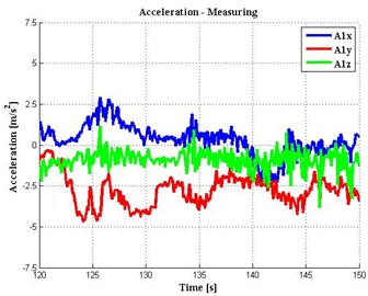
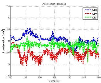
Because the action of mechanical vibration in the car cabin to the driver and passengers is always multi-axis must be reproduce in the laboratory testing the same load signals. Because the action of mechanical vibration in the car cabin to the driver and passengers is always multi-axis must be in the testing laboratory to reproduce the same load signals. For the realization of motion in space, it is appropriate to use a device with 6 degrees of freedom of the hexapod (Fig. 1). The general 3D motion can be realized using 6 linear actuators, i.e. 3-axis movements in x, z, y and 3 rotations around these axes. The linear movement of individual motors logically in sum gives a general spatial motion. If we will know the position of movements of at least two points in space is possible make mathematical transformations to obtain the linear movement of the all (6) linear drive, but also by knowledge of linear motion actuator can realize the general movement of two points in space. The main goal of this theory was measurement of the real general movements of two points in space (in the cabin of a car), and transforming these to the linear movement drives (Fig. 6). By using these linear movements reproduce the general real movement back two points in space on hexapod. In the event that this movement we can achieve, we may say: that laboratory tests correspond quite real and can fully replace this. Repeatability of such laboratory tests is almost in our experience 95 %:
Fig. 1Transformations vector and components of vector
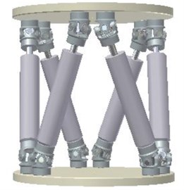
a) Schema of hexapod
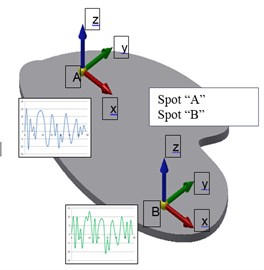
b) Working platform
3. Calibration of sensor before measurement
To obtain good results it is necessary to pay great attention to the calibration of the sensors (Fig. 2) and the entire measurement chain. Calibration is performed before each experiment. To calibrate the accelerometer was made by a special device into which they are inserted at the same time all the sensors in order to ensure equal conditions of calibration. Calibration of all sensors is performed at a same time, sequentially in all axes. The measuring device is used PC DEWE 5,000. Calibrations are always saved with the measured data.
Fig. 2Calibration of the sensor
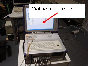
a)
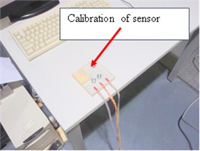
b)
4. Measurements in a cab car
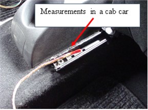
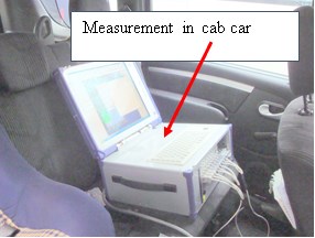
For measurements in a cab car, we placed the sensor at a predetermined place (Fig. 3). For these measurements were used acceleration sensors that were placed on the anchorage driver’s seat, two sensors at the rear and one front sensor. Measuring devices DEWE PC 5000 laid on the back seat. With the driver goes the operator, who takes care of measurement. To measure was chosen straight stretch of road with asphalt surface, the length of 3 km. There was recorded: slow start of the car, driving at a constant speed of 50 km/h. The measurement results are described in chapter 7.
Fig. 3Measurements in a cab car
a)
b)
5. Measurements on the hexapod
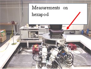
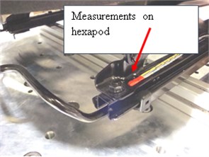
To measure on the hexapod we at first put the same driver's seat on the working platform hexapod (Fig. 4). This platform is supported by six independent linear motors that create together the linear and rotational movement. The sum may platform to move generally in the space. Again, we placed the sensor at a predefined location (as in a car cabin) for anchoring the driver's seat, two sensors at the rear and one front sensor. Measuring devices DEWE PC 5000 laid on the worktable.
Fig. 4Measurements on the hexapod
a)
b)
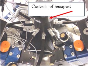
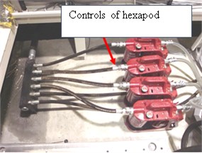
Fig. 5Control of hexapod
a)
b)
We used hexapod is parallel mechanism having a base underneath, as the arm of variable length are used linear hydraulic motors. Motion control of linear motors is realized by servo drives. It is possible to achieve very rapid changes in position and high speed lifts. Weight of moving parts is low, all the arms contributes to the overall general movement. The shortcomings seem to be counting errors in each axis (Fig. 5).
For the realization of general motion, we must define the current movement of the 6 independent linear motors. On the basis of these signals is fed into the cylinders pressurized hydraulic oil.
6. Comparison of the two measurements
Fig. 6The results of measurements in the cab car and on hexapod
a) Spot „A“ in the cab car
b) Spot „A“ on hexapod
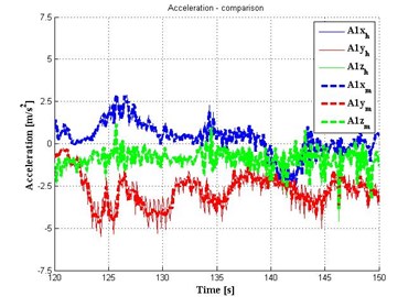
Fig. 7Comparison measurements in cab car and on hexapod
7. Conclusion
The results indicate that the agreement was reached 97 % of the real and simulated motion. We can replace actual testing of car seats in laboratory tests on the hexapod (Figs. 6 and 7).
References
-
Martonka R., Fliegel V. Hexapod-the platform with 6DOF. 54th International Conference of Machine Design Department, Hejnice, Czech Republic, 2013, p. 111-116.
-
http://www.inova.cz/, Inova Testing Systems, Hydraulic Bearing Linear Actuators, 2014.
