Abstract
The paper concerns the assessment of a combustion process correctness in direct injection compression-ignition engine of a HDV vehicle. The method of such diagnoses is based on the vibration acceleration signal and its digital processing. Identification of a combustion process runs and detection of some failures taking place in the combustion chamber during engine working cycles are important in the point of view of environmental and operational engines characteristics. That is why the authors considered this scientific problem, trying to show the possibility of the precise diagnosis of combustion process regarding with the requirements of OBD regulations. The method of misfire identification for a compression-ignition engine, based on results of parameterizations of a time-frequency a(t,f) map of an engine vibration signal taken from engine heads, was used in the diagnostic process. Parameterization of a(t,f) map gives measures covariable with misfire in a cylinder of an internal combustion engine and obtained point measures can be used as diagnostic parameters for combustion process control and its diagnostics. Reliability of a method for combustion process assessment was checked for research conducted in stationary and real engine operation conditions.
1. Introduction
Chemical conversions of a fuel-air mixture in a compression-ignition engine belong to a continuous process. Although it is, it can be singled out three characteristic combustion periods: I – initial period until first signs of the reaction take place, II – period of reaction development in all space of the combustion chamber, III – finish period of the fuel burning in the volume filled with the flame. The quality of an injection process, air whirling in a combustion chamber and the composition of the combustion mixture and gases that change constantly influence on the quality and runs of the processes in each of the mentioned periods.
Ignition in compression-ignition engines is qualified with the obtaining of some critical reaction speed, in which the stream of the heat emission assures the flame comes out. The necessary condition for this process is to assure the collision of reagent molecules or atoms. Frequency of collisions is proportional to the concentration of molecules or atoms (depends on a temperature and an activation energy). This terminal energy allows a molecule to enter reactions. A lower reaction energy will react more quickly and thoroughly and higher its speed.
According to physical and chemical combustion theory there are high-temperature and low-temperature ignitions in compression-ignition engines. The flame during high-temperature ignition is a result of the exothermic reaction acceleration in a high temperature, in a result of which hydrocarbon molecule attachments break and free CH3 and CH2 radicals arise. When reactions accelerate, the speed of a heat emission increases. If it exceeds the speed of a heat being given back, the reaction accelerates and a mixture temperature increases, what makes an ignition takes place. It is a continuous reaction, in which acceleration is the condition to start a chain reaction. The ignition appears in the point of a chamber where the highest temperature takes place (min 1200 K), in other case a start of a combustion reaction do not come forward.
There is not disintegration of hydrocarbons molecules on free radicals in the low-temperature ignition being placed in CI engines (less than 700 K), but only oxidation of molecules as a result of an endothermic peroxides creation for specified compound, type R-CH2-O-O-H. The process lasts until contents of these compounds in a charge do not exceed a critical density. Above this density, detonation disintegration of peroxides and so-called cold flame take place, which depends on active molecules diffusion to fresh mixture. The next phase of the chemical reaction in a low-temperature ignition is the acetic aldehyde oxidation (creation of new types of peroxides – detonation disintegration above a critical density). The flame appears and a pressure and a temperature increase. After that phase, the heat detonation and emission of all fuel energy take place. In a result, carbon dioxide and water arise (multi-point ignition). A normal combustion process starts after this kind of ignition.
When the proper run of the above processes is assured the combustion process occurs and its run is correct. All disruptions in this process cause that some irregularities appear during a production of chemical combustion reactions, what can cause the lack of a combustion or its run with products of an incomplete and deficient combustion.
2. Research engine and conditions
Research in potential operating applications were conducted on a 12-cylinder, compression-ignition (CI) and direct injection engine, type 2112 SSF the SU45 locomotive (Table 1).
Table 1The 2112SSF engine technical data
Feature/parameter | Type of an engine |
2112 SSF | |
Type | CI, 4-stroke |
Cylinder bore × piston stroke: D × S [m] | 0,210 × 0,230 |
Compression ratio (ε) | 11.3 |
Crankthrow/length of connecting rod (r/l) | – |
Engine displacement (Vss) in [m3] | 96.6 × 10⁻³ |
Amount of valves | 4 |
Injector type | Multi-hole (7 holes) |
Pressure of the injector opening (pinj) in [MPa] | 26 ± 0,5 |
Geometric start of fuel delivering (αinj) | 32° before TDC |
Cylinder system/amount | V12 – 90° |
Mean effective pressure in [MPa] | 1.37 |
Maximum effective power (Ne) in [kW] | 1655 (1500 rpm) |
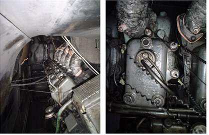
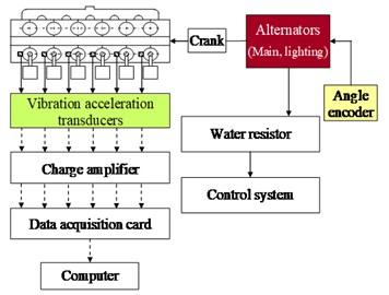
Fig. 1The placement of the measuring points on the engine and a test stand: a) the view of the engine with accelerometers and optical crank angle encoder, b) the scheme of a measuring test stand
a)
b)
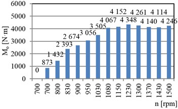
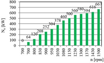
The test measuring points were located on the engine head. The points were selected according to the principle that the sensor should be placed closest to the point where the tested process-related vibration signal is generated (Fig. 1). The following elements of a measuring set were used in the tests: vibration transducers for the Z direction (Brüel&Kjær, type 4391), vibration signals calibration unit (Brüel&Kjær 4294), crank angle encoder (Wobit MOK), charge amplifier (NEXUS, type 2692), data acquisition card (National Instruments, type PCI-4472), water resistor with the control system, coolant and lubricant temperature transducers. The torque and power was being measured and controlled with the help of the water resistor stand. All velocities and torques defined with the locomotive regulating unit position were taken as the working points (Fig. 2).
Fig. 2The diesel engine operational points being considered in the research
a)
b)
The main idea was to recognize and describe functional relations between the combustion process (main process of combustion engines) and a diagnostic signal, which was in this case the vibration acceleration signal taken from the specified places located on the engine (Fig. 3).
Fig. 3Scheme of vibroacoustic signal generation in a combustion engine, including the wear process [1-3]
![Scheme of vibroacoustic signal generation in a combustion engine, including the wear process [1-3]](https://static-01.extrica.com/articles/15473/15473-img5.jpg)
Such relations can be described by the Eq. (1) [4]:
where: S(Θ)={s1,s2,…,sn} – diagnostic signal vector, X(Θ)={x1,x2,…,xn} – state parameters vector, Y(Θ)={y1,y2,…,yn} – vector of a control process, Z(Θ)={z1,z2,…,zn} – disruptions vector, Θ – operational ageing measure, Φ – assigning operator.
An S(Θ) vector contained: s1-s6 – vibration accelerations for each cylinder number, X(Θ) – geometrical parameters and kinematic characteristics (also stating technical state of the object), stationary regulation characteristics, Y(Θ) – engine control parameters: velocity, torque, fuel dose stream, recirculation factor, charging factor, Z(Θ) – vibrations from other sources, ambient temperature, ambient pressure and relative humidity.
3. Combustion process analysis by the use of vibration acceleration signal characteristics
The ignition causes the impulse changes of the vibration signal amplitudes, the combustion process has its representation in a vibration signal. The signal is distinct in each working cycle and for the each cylinder, what confirms the method reliability in relation to detection procedures for multi-cylinder compression-ignition engines (Fig. 4).
Fig. 4Vibration acceleration runs in the Z dimension (az) of the cylinder heads no. 4-6 for the 2112 SSF diesel engine (n= 900 rpm and Mo= 2674 N·m)
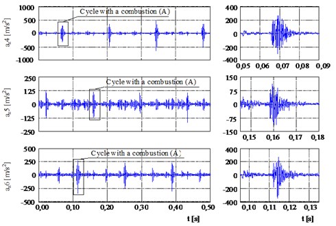
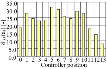
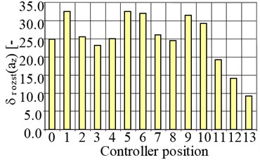
The fourth cylinder had the lowest and the sixth cylinder the highest relative change of the point measures in the case when the effective power had changed. These two cylinder numbers represents the worst and best conditions for misfire detection strategy. When a misfire event occurred, it caused that the vibration signal amplitude decreased irrespective of the cylinder number and working conditions. In the case of the fourth cylinder, misfire event occurrence made the peak value decrease 8-31 times. In the case of the peak-to-peak value relative decrease of this measure was 9-32 for 4th cylinder (Fig. 5).
Fig. 5Relative decrease of the peak value (δsz) and peak-to-peak value (δrozst) of the vibration acceleration of a diesel locomotive engine for the fourth cylinder as a result of misfire occurrence
a)
b)
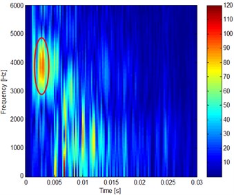
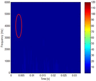
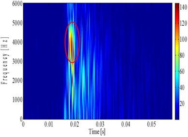
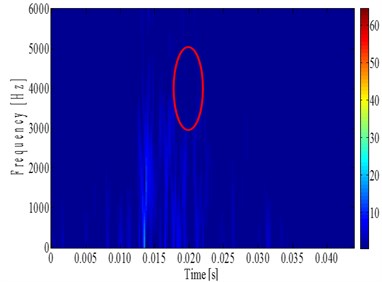
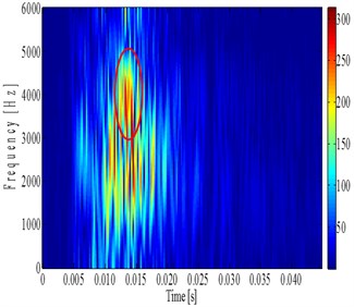
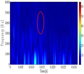
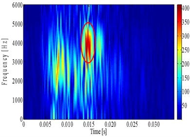
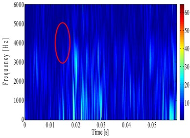
The JTFA maps were obtained for a lack of combustion in a cylinder and when combustion took place (Fig. 6-9). In this case, a peak value of vibration accelerations in the range of frequency of 3000-5000 Hz, determined on the basis of time-spectral map, was the parameter that described lack of an ignition in the cylinder or a combustion process for a diesel locomotive engine. Changes of a parameter were described with the dynamics that reached 24-34 dB. Increase of the effective power does not change the quality of the combustion identification, but shows additional sources of the vibration signal generation for another dynamic processes (impulse closing of valves and other kinematic pairs movements). It shows also the higher energy of the process with giving more fuel dose and its energy release. The higher effective power means also the increase of the vibration acceleration amplitudes from other sources what proves the need of the careful identification of the frequency range of the searching the combustion process on the a(t,f) maps [5-7].
Fig. 6The vibration acceleration runs in the Z dimension (az) of cylinder heads at the 2112 SSF engine (n= 700 rpm and Mo= 0 N·m) for: a) combustion process, b) misfire event
a)
b)
Fig. 7The vibration acceleration runs in the Z dimension (az) of cylinder heads at the 2112 SSF engine (n= 700 rpm and Mo= 873 N·m) for: a) combustion process, b) misfire event
a)
b)
Fig. 8The vibration acceleration runs in the Z dimension (az) of cylinder heads at the 2112 SSF engine (n= 1150 rpm and Mo= 4152 N·m) for: a) combustion process, b) misfire event
a)
b)
4. Conclusions
Described method of a combustion process identification in multicylinder diesel engine of off-road vehicle appeared to be reliable tool for such diagnostic process. Direction of signals being recorded parallel to a longitudinal axis of a cylinder was giving the clear and high S/N (Signal/Noise) diagnostic signal, based on the vibration process characteristics. When the engine effective power was increasing (Fig. 5), the dynamic of the correlation between the correct combustion process and for misfire phenomenon was also increasing till the 0.87Ne,nominal, what proves the functional relation between the amount of the energy released from fuel dose in an oxidation process taking place in an engine combustion chamber and the energy of the vibroacoustic process. Above this value, the amount of fuel doses for each engine working cycle were so high that combustion processes were incomplete and the mechanical efficiency was decreasing by the higher friction losses.
Fig. 9The vibration acceleration runs in the Z dimension (az) of cylinder heads at the 2112 SSF engine (n= 1500 rpm and Mo= 4246 N·m) for: a) combustion process, b) misfire event
a)
b)
Vibration acceleration was used as a physical parameters giving the information on the combustion process run and its correctness, and as a diagnostic parameters should be used the three most sensible and reliable amplitude measure: peak and peak-to-peak values, and root mean square value (diagnostic parameters for OBD diagnostic strategy). Vibration velocity was not used because of the low changes of the amplitude and different behaviour with Ne increase (proved in previous author’s research). The monitoring of the combustion process based on JTFA method and vibration signal parameters allows an unambiguous misfires detection, which is an advantage of those methods over the currently used ones (detection of each particular combustion for each cylinder). The JTFA method is characterized by the high dynamics of parameter changes, which reflects appearing or a lack of an ignition in an engine cylinder (24-34 dB). The relative error of a method did not exceed 10 % for the examined type of engine and was at the same level for another combustion engines of different vehicles applications.
References
-
Cempel C. Basics of Vibroacoustic Diagnostics of Machines. Scientific-Technical Publishing Houses, Warsaw, 1982.
-
Korbacz J. Trends and problems in a processes diagnostics. Diagnostics, Vol. 30, Issue 1, 2004.
-
Korbicz J., Kościelny J. M., Kowalczuk Z., Cholewa W. Processes diagnostics. Models. Methods of Artificial Intelligence. Applications. Scientific-Technical Publishing Houses, Warsaw, 2002.
-
Szymański G. Problems of combustion engines diagnostics with the use of resonanse vibrations. Dissertations No. 500, Poznan University of Technology Publishing House, Poznań, 2013.
-
Carlucci A. P., Chiara F. F., Laforgia D. Analysis of the relation between injection parameter variation and block vibration of an internal combustion diesel engine. Journal of Sound and Vibration, Vol. 295, 2006.
-
Charles P., Sinha J. K., Gu F., Lidstone L., Ball A. D. Detecting the crankshaft torsional vibration of diesel engines for combustion related diagnosis. Journal of Sound and Vibration, Vol. 321, 2009.
-
Shirazi F. A., Mahjoob M. J. Application of discrete wavelet transform (DWT) in combustion failure detection of IC engines. 5th International Symposium of Image and Signal Processing and Analysis, 2007.
