Abstract
There are many applications in non destructive testing, calibration of acoustic emission transducers, medicine, mechatronics etc., where waveguides with dispersive wave propagation properties are used. Generation of arbitrary displacements in this kind of waveguides is important and difficult. Possible solution to this problem is application of wave synthesis technique. This research shows that suggested technique allows to obtain arbitrary displacements of known form and duration in plates and stripes. Measurements of displacements were done in steel plate and stripe. Scanning of surfaces proved that it is possible to obtain arbitrary displacements in selected areas of the waveguides.
1. Introduction
Waveguides with dispersive wave propagation properties are used in many fields: non destructive testing, calibration of acoustic emission transducers, medicine, mechatronics etc. [1-4]. Generation of arbitrary, micro seconds long vibrations in this kind of waveguides is difficult. This problem becomes especially important when wave propagation distance is significantly greater then waves length. Because of wave dispersion mechanical displacements form depends from wave propagation distance, geometry of waveguide (dispersive media), excitation signal bandwidth.
Effects of dispersion can be compensated using a time reversal method [5–10]. This method does not evaluate whole systems (actuator-waveguide-amplifier) transfer function and hence, it is possible to form short mechanical displacements, but the measured signal form and spectrum are not arbitrary. The method is not robust to noise and requires additional filtering.
Possible solution which is presented in this research is application of wave synthesis technique. It doesn’t have disadvantages of time reversal method, whole systems transfer function is evaluated when calculating necessary excitation signal. Calculated excitation signal compensates effects of wave dispersion and allows obtaining arbitrary, known form and duration displacements in transfer function measurement area.
Despite possibility to compensate effects of dispersion, wave synthesis technique evaluates transfer function only of small area of the waveguide, hence displacements in other locations of the waveguide that are within same propagation distance can be different, depending on the type of the waveguide and variation of the pulse response.
This paper presents application of wave synthesis technique in stainless steel plates and cylindrical stainless steel stripes (both are waveguides which have dispersive wave propagation properties). Application of the technique allowed to obtain 1 µs-10 µs long arbitrary displacements in pulse response measurement points. Because, in most cases, arbitrary displacement is needed, not in a single point, but in an area of the waveguide, scanning and illustration of displacements in selected areas of the waveguides was done. Results allowed to evaluate possibility to obtain arbitrary displacements in selected areas of the waveguides.
2. Arbitrary form displacements in cylindrical waveguides
Arbitrary displacement in selected area of the waveguide requires excitation signals, which can compensate for the effects of wave dispersion. It can be calculated as the deconvolution of the pulse and arbitrary signal. The simplified algorithm for the calculation of the excitation signal is shown in Fig. 1.
Fig. 1Simplified wave synthesis technique algorithm
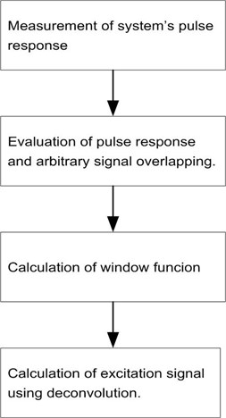
The wave synthesis technique was used to obtain arbitrary type displacements in several waveguides. In each case excitation signal was calculated to obtain the arbitrary type displacement in the selected area of the waveguide. The measurement stand block diagram is presented in Fig. 2.
Fig. 2Waveguides displacement measurement stand block diagram
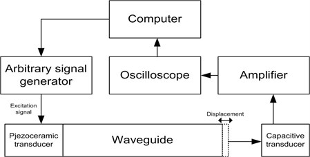
The measurement stand consisted of the displacement measurement equipment, a computer that was used for data storage and arbitrary signal calculation, and an electrical arbitrary signal generator.
The systems pulse response was measured by feeding a 1 µs-long electrical pulse to the piezoceramic that was attached to the end of the waveguide. The form of the resulting displacement was different from the excitation signal, due to the effect of the wave dispersion. In the case of the cylindrical waveguide, the measured pulse response at the other end of the waveguide was a chirp-type signal, as shown in Fig. 3(a).
The wave synthesis technique allowed us to obtain different form arbitrary displacements, as shown in Figs. 3(b)-(d).
The measurement results in Fig. 3 showed that the arbitrary wave synthesis technique allowed us to obtain arbitrary displacements in the pulse response measurement point. In many cases, the arbitrary displacements are needed in certain area of the waveguide. To prove that other points of the waveguide, that are at same distance from the excitation source, have the same type of displacement, we studied two cases of wave synthesis applications. The arbitrary-type displacements were obtained using longitudinal waves in steel rods and lamb waves in steel plates.
Fig. 3Signals measured at the receiving end of the cylindrical waveguide
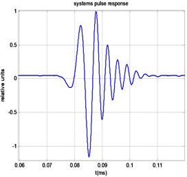
a) Waveguides pulse response
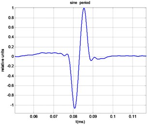
b) Synthesised sine period
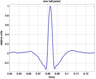
c) Synthesised sine half period
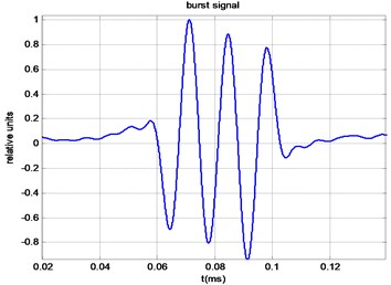
d) Synthesised burst of three sine periods
Selected areas of the waveguides were scanned. The cylindrical waveguides measurement stand block diagram is shown in Fig. 4(a). The piezoceramic transducer was attached to one end of the rod and excited from the arbitrary generator. The other side of the waveguide was scanned with a capacitive transducer according to the x and y axes. The measurement results are given in Fig. 4(b).
Fig. 4Displacement measured at the end of the cylindrical waveguide
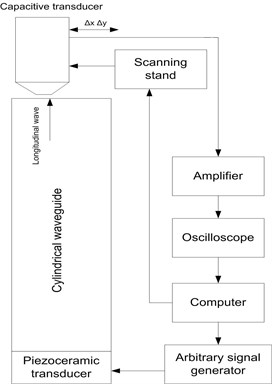
a) Measuring stand block diagram
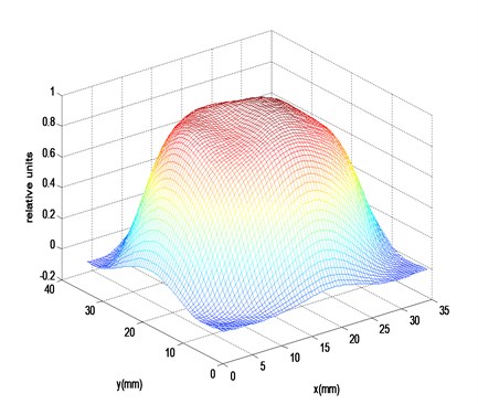
b) Measured displacement time frame
3. Arbitrary form displacements in plates
In another case, we performed a scan on a stainless steel plate. The measurement stand block diagram is shown in Fig. 5(a). In the selected area, we obtained arbitrary-type displacements. In Fig. 5(b), we show a single frame of the propagating sine period displacement.
Fig. 5Synthesised Lamb wave signal measured in the stainless steel plate
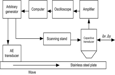
a) The measurement stand block diagram
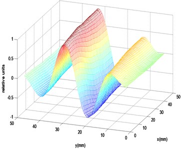
b) Measured displacement frame
4. Conclusions
The surface displacements scans demonstrated that, by using wave synthesis, arbitrary displacement can be obtained, not only in the pulse response measurement point, but in all of the surface area that is at the same distance from the excitation source and has the same pulse response. The measured surface displacements at waveguides with different geometry proved that the described wave synthesis method could be used to obtain arbitrary displacements in any kind of waveguide that has dispersive properties.
References
-
Yamasaki T., Tamai S., Hirao M. Optimum excitation signal for long-range inspection of steel wires by longitudinal waves. Journal of NDT&E International, Vol. 34, 2001, p. 207-212.
-
Shatalov M., Marais J., Fedotov I., Tenkam M. D. Longitudinal vibration of isotropic solid rods: from classical to modern theories. Journal Advances in Computer Science and Engineering, Vol. 10, 2011, p. 187-214.
-
Benatar A., Rittel D., Yarin A. L. Theoretical and experimental analysis of longitudinal wave propagation in cylindrical viscoelastic rods. Journal of the Mechanics and Physics of Solids, Vol. 51, 2003, p. 413-1431.
-
Hayashi T., Song W. J., Rose J. L. Guided wave dispersion curves for a bar with arbitrary cross-section, a rod and rail example. Journal of Ultrasonics, Vol. 41, 2003, p. 175-183.
-
Mathias F. Time reversal of ultrasonics fields – Part I: Basic principles. Journal Transactions on Ultrasonics, Ferroelectrics and Frequency Control, Vol. 39, Issue 5, 1992, p. 555-566.
-
Gangadharan R., Murthy C. R. L., Gopalakrishnan S., Bhat M. R. Time reversal technique for health monitoring of metallic structure using Lamb waves. Journal of Ultrasonics, Vol. 49, 2009, p. 703-705.
-
Park H. W., Kim S. B., Sohn H. Understanding a time reversal process in Lamb wave propagation. Journal of Wave Motion, Vol. 46, 2009, p. 451-467.
-
Watkins R., Jha R. A modified time reversal method for Lamb wave based diagnostics of composite structures. Journal of Mechanical System and Signal Processing, Vol. 31, 2012, p. 345-354.
-
Griffa M., Anderson B. E., Guyer R. A., Ulrich T. J., Johnson P. A. Investigation of robustness of time reversal acoustics in solid media through the reconstruction of temporally symmetric sources. Journal of Physics D: Applied Physics, Vol. 41, 2008, p. 1-15.
-
Mathias F. Timer reversal of ultrasonic fields – Part I: Basic principles. Journal of Transactions on Ultrasonics, Ferroelectrics and Frequency Control, Vol. 39, 1992, p. 555-565.
