Abstract
This paper proposes a new active vibration control (AVC) method with online secondary path modeling (SPM). The proposed method uses FXLMS algorithm in adapting the active control filter and a modified variable step size (VSS) LMS algorithm based on delay coefficient technique in adapting the secondary path filter. The proposed method also introduces an auxiliary noise power scheduling to eliminate the contribution of auxiliary noise on the residual vibration. The simulation results and experimental results show that the proposed method has the lowest computational complexity and the fastest convergence rate comparing with previous methods. With the proposed auxiliary noise scheduling strategy, the contribution of auxiliary noise to the residual vibration has been almost attenuated.
1. Introduction
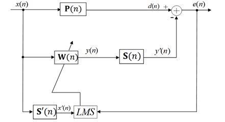
In the recent year, adaptive filter active vibration control (AVC) method has drawn wide attention, as it has strong adaptability and is easy to implement without accurate identification model [1, 2]. The adaptive finite impulse response (FIR) filter used together with the LMS algorithm is probably the most widely used adaptive algorithm for practical applications due to its simplicity, robustness and effectiveness [3]. One of the most popular adaptive algorithms is the filtered-x least mean square (FXLMS) algorithm based on a feed-forward structure [4]. See Fig. 1. The main difference between AVC system and adaptive signal processing system is the presence of an electro-vibration channel, called the secondary path, leading from the adaptive controller output to the error sensor. Indeed, an accurate secondary path modeling (SPM) is very crucial to the working of adaptive AVC system. The effect of secondary path modeling error on the performance of FXLMS algorithm has been studied in [5, 6]. It has been shown that fast and precise secondary path modeling is one of the most important factors for faster convergence of an AVC system using the FXLMS algorithm.
Fig. 1Block diagram of feedforward FXLMS AVC system
There are two strategies for secondary path modeling, online modeling and offline modeling method. Considering the controlled structure’s uncertain characteristics, AVC with online identification is a hot and difficult point. In some case, offline modeling technique can simplify the active control algorithm to a great extent when the system parameters vary slowly or nearly not vary. In some application, however, the secondary path is usually time varying or non-linear, so online modeling technique is required to ensure convergence of the active control algorithm and the stability and accuracy of AVC system [7].
The basic online secondary path modeling method using auxiliary random noise was proposed by Eriksson [8]. In Eriksson’s method, however, the interaction between secondary path modeling filter and active control filter may lead to a divergence of adaptive active control algorithm in the worst case. In order to improve the performance of Eriksson’s method, a parallel online modeling algorithm using three adaptive filters with a delay unit in the output port of the primary path is proposed by Zhang Ming in [9, 10]. From the further analysis of Zhang’ method, we can know the weights of the third adaptive filter converge to zero vectors after adaptive algorithm converging. Once the system is disturbed, the weights have to be adjusted from the zero vectors, and thus a bad performance on the reconvergence of AVC system is inevitable. Akhtar et al. [11, 12] used the same error signal for updating the noise control process as used for the secondary path modeling process. In Akhtar’s method, using VSS-LMS algorithm can increase the modeling accuracy and improve system convergence correspondingly without increasing the amount of calculation. However, the varying strategy of the step size for secondary path modeling is not easy. Some experience parameters have to be set before the control system working.
For the FXLMS algorithm with online secondary path modeling using auxiliary random noise technique, the large auxiliary noise can lead to a quick acquisition of accurate secondary path estimation. However, it will also increase the residual vibration greatly, and thus deteriorate the vibration reduction of AVC system. So an auxiliary noise power scheduling technique is necessary, in order to obtain an accurate secondary path model and reduce the influence of auxiliary noise to the residual vibration.
Auxiliary noise power scheduling techniques were studied [12, 13]. Akhtar proposed an auxiliary noise power scheduling strategy using the ratio between the power of residual signal and an error signal [12]. However, the varying strategy is not easy. Some experience parameters have to be set before the control system working. The problem of Carini’s method [13] has low tracking capability for the vibration path perturbation because of freezing of the step-size to lower value and is not suitable for time varying secondary path AVC system.
2. The proposed method
On the basis of the above analysis we can know the modified version FXLMS proposed in [12, 14] gives a good performance, but its computational complexity is even higher than the three adaptive filter-based methods [10]. Here, we propose a new method for online secondary path modeling in active vibration control systems. The block diagram of the proposed method is shown in Fig. 2. The proposed method is a modified version of the basic method, proposed by Eriksson et al. The computational complexity of the proposed method is comparable to the Eriksson’s method, and it gives best performance among the existing methods.
The proposed method introduces two improvements on the online secondary path modeling comparing with the methods mentioned in the previous section. Firstly, the FXLMS algorithm is employed instead of the Modified-FXLMS algorithm. Because the FXLMS algorithm is simple in structure, the computational complexity of the proposed method is less than that of Fig. 3. However, the convergence speed of W(n) would be degraded due to the slow convergence of FXLMS algorithm. In our study, we propose a simplified variation rule of the step-size based on delay coefficient technique which makes up for the deficiency of slow convergence at a reasonable computational cost. Secondly, a simplified auxiliary noise scheduling strategy is introduced to eliminate the contribution of auxiliary noise on the residual vibration. The contribution of auxiliary noise to the residual vibration has been almost attenuated. Computational complexity of the proposed has been decreased.
Fig. 2The proposed algorithm for online secondary path modeling
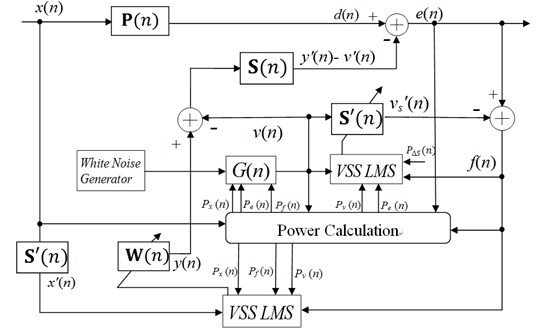
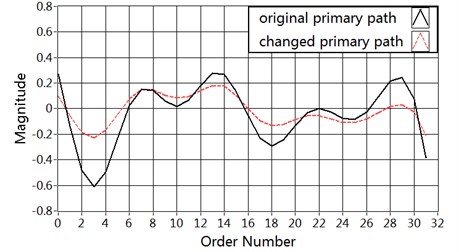
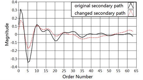
Fig. 3Magnitude of the vibration paths: a) primary path P(n), b) secondary path S(n)
a)
b)
The proposed method uses f(n)as the error signal of the secondary path model filter S'(n) and control filter W(n). The secondary path modeling filter S'(n) and the control filter W(n) are adapted with LMS algorithm and FXLMS algorithm, respectively, as follows:
See Eq. (3), f(n) has two parts: the first part [d(n)-y'(n)] carries error information about the iteration of the AVC filter W(n), but acts as interference to the secondary path modeling filter S'(n). The second part [v'(n)-v's(n)] carries error information about the iteration of the SPM filter S'(n), but acts as interference to W(n).
Further derivation of the error signal f(n) can be expressed as:
where, Wopt(n) is optimal value. S(n) denotes the real impulse response vector of the secondary path. When the AVC system converges (n→+∞), y'(n) trends to d(n) and S'(n) trends to S(n).
The estimation error of the active control filter W(n) and the secondary path modeling filter S'(n) can be expressed as:
From Eq. (14) and Eq. (1) we can get:
2.1. Step size variation
Usually is set to a small value in order to prevent the system suffering from diverging. However, in our study, we employ the FXLMS algorithm instead of the Modified FXLMS algorithm in order to realize improved performance at a reasonable computational cost. And thus, the convergence speed of the active control filter would be degraded due to slow convergence of FXLMS algorithm. In order to improve the convergence of the active control filter, we vary the value of the step size according to the status of the AVC system. The convergence of the AVC system is relevant to the power of original vibration and the power of the generated white noise [8]. From further analysis, we can know not only the power of the generated white noise but also the estimation error of the active control filter could affect the convergence of the AVC system. From the derivation of , we can know the estimation error included in the error signal . In other words, the used as the error signal of the AVC controller, reflects the convergence status of the AVC system [11]. Consequently, in order to improve the performance, the adaptive filter step size adaptively changes following power variations of the reference signal, the generated white noise and the estimation error of the active control filter alike. By considering the above situations, we propose the following procedure to vary the step size during system operation:
The power of these signals is estimated as:
where is the forgetting factor (0.91).
When the power of the reference signal is increased, a small value of can prevent the system from diverging. When the power decreases, a large value of improves the vibration attenuation and convergence rate of the adaptive filter. When the power of the generated white noise increases, the convergence rate of secondary path modeling would increases. This allows using a larger during system operation. For the similar reason, a large estimation error of the active control filter means the AVC system is farfrom steady state, this moment, a small value of is necessary to improve the system performance.
As mentioned before, the modeling filter of the proposed system estimates the secondary path transfer function using a modified version of the VSS-LMS algorithm. Studies have shown that the value of step-size parameter has important influence on the modeling accuracy and the system convergence, consequently, should be varied in accordance with the state of the SPM filter and its distance to the steady state. From the discussion about above, we can know that carries error information about the iteration of , but acts as interference to the SPM filter . The step size should be calculated as the rule trying to reduce the influence of disturbance signal .
If the signal could be gotten directly, the secondary path modeling filter should be adapted as follows:
So we can consider:
Further derivation of can be gotten:
Thus, the bad influence on online secondary path modeling from the disturbance signal can be reduced. The signal is uncorrelated with . Further derivation of the ratio can be expressed as:
where .
So we can get approximately:
If the power of the estimation error could be gotten, we can adapt the secondary path modeling filter using the evaluation of Eq. (19). In order to get the accurate estimate value of , the delay coefficient technique is adopted in our study, which has been largely applied in the field of acoustic echo cancellation [14]. The delay coefficient technique derives from the observation that the system error tends to have a uniform distribution on its coefficients. By delaying by samples the internally generated signal sent to the secondary path, the steady-state value of the first coefficients of the secondary path modeling filter becomes 0, and the instantaneous value of the first delay coefficients can be used for estimating the system distance:
where the first coefficients of the secondary path modeling filter .
So the power of the estimation error can be estimated as:
The last coefficients of , is the estimation vector for the impulse response of the secondary path. and are all adapted with LMS algorithm, as follows:
where:
2.2. Auxiliary noise power scheduling
In general, an unavoidable problem of the online secondary path modeling methods using the auxiliary noise technique is that a large auxiliary noise could lead to a quick acquisition of an accurate secondary path modeling but will greatly increase the residual vibration [11]. In order to obtain an accurate secondary path model and reduce the influence of auxiliary noise to the residual vibration, one of the solutions is auxiliary noise power scheduling technique. Large auxiliary noise is injected to obtain an accurate model of secondary path quickly at the start-up of AVC system, or when a sudden and large change occurs in the secondary path. But the power of the auxiliary noise should be kept as low as possible when the AVC system is close to steady-state.
The training signal for the modeling filter of the secondary path is , which is injected at output and is defined as:
where is an internally generated zero-mean white Gaussian noise signal. is the parameter that controls the injection of the white noise.
The value of the gain should be varied in accordance with the power of original vibration and the modeling error of the secondary path. In other words, the strategy schedule based on both the convergence status of the SPM system and the power of the reference signal .
Here, let us first discuss the ratio . Since is uncorrelated with and , further derivation of the error signal as follows:
As stated in [11], the injected random noise is low level excitation signal as compared with the reference signal Initially at the canceling signal so and , and hence . In steady state, when the AVC system comes to converge properly, trends to , trends to , the value of is only correlated with the distance between and the real value.
The proposed strategy can be formulated as follows:
From Eq. (14), it can be seen that the power of is scheduled by taking into account the convergence status of the AVC system and the power of the primary vibration. In fact, after the active control filter comes to converge, the value of becomes very small. By using Eq. (14), the power of is, therefore, scheduled to a very low level. As a result, the contribution of auxiliary noise to the residual vibration is greatly alleviated. And thus improve the vibration attenuation of AVC system.
2.3. Computational complexity analysis
Table 1 compares the computation complexity of the proposed method with that of Eriksson’s, Zhang’s, Akhtar’s, and Carini’s method.
Table 1Comparison of algorithms iterative computation
+ | × | Example | |
Eriksson’s method | 2N+3M+2 | 2N+3M-1 | 393 |
Zhang’s method | 2N+3M+2H+7 | 2N+3M+2H+3 | 530 |
Akhtar’s method | 3N+4M+7 | 3N+4M+13 | 576 |
Carini’s method | 5N+5M+3D+8 | 6N+5M+3D+22 | 996 |
Proposed method | 2N+3M+2D+3 | 2N+3M+2D+16 | 475 |
50, 32, 32, 16 | |||
Here and are tap-weight lengths of the control filter , and SPM filter , respectively. is tap-weight length of the third filter in the Zhang’s method. The tap-weight length of the part of the SPM filter is in Carini’s method, and the SPM filter is used for estimating the modeling error of the secondary path. The Eriksson’s method has the lowest computational cost among the other existing online secondary path modeling methods, because it’s the basic online secondary path modeling method which fixed step-sizes are employed for both the adaptive filters, and no auxiliary noise scheduling strategy is employed. The Carini’s method (the control filter is adapted with a fixed step-size) has the highest computational cost comparing with the other methods discussed in this paper. The main reason of the high computational cost is the using the delay coefficient technique for online estimation error of the secondary path, which equivalent to introducing the third adaptive filter. The computation complexity of Zhang’s method is also very high due to introducing the third adaptive filter. Akhtar’s method avoiding using the third adaptive filter, has lower computational cost than Carini’s method, however, it adds two extra (fixed FIR) filters for and . The proposed method has lower computational cost as compared with Akhtar’s method, because no experimentally determined parameter is employed for the iteration of the adaptive filters and auxiliary noise scheduling strategy, and the variance rules for step size parameter and auxiliary noise scheduling strategy in the proposed method are simpler than that in Akhtar’s method.
3. Simulation results and performance evaluation
In this section we provide three simulation experiments to compare the performance of the proposed algorithm with Eriksson’s, Akhtar’s, and Carini’s method based on LABVIEW version 2012.
The performance comparison of the AVC systems is done on the basis of different performance measures. They are:
The relative modeling error of the secondary path, defined as:
To signify performance of the system on vibration reduction, the following equation is used:
Three distinct cases are considered for the evaluation. In Case 1, the reference signal is a tonal signal. In Case 2, the reference signal is a broadband signal. In Case 3, we consider both the primary and the secondary paths transfer functions are suddenly changed during operation. The structure vibration paths and are modeled as FIR filters of tap-weight lengths 32 and 64, respectively. The FIR filter coefficients of the primary path and secondary path are shown in Fig. 6. In this figure, the solid line represents the primary path and the secondary path at the starting point in Case 1 and Case 2. The dashed line represents the changed primary path and secondary path at the 40000th sample in Case 3. The length of active control filter modeled as FIR filter is 128, and the length of secondary path modeling filter modeled as FIR filter is 64 in Eriksson’s, Akhtar’s methods. In Carini’s and proposed method, and are modeled as FIR filters of tap-weight lengths 32 and 32, respectively. All of the adaptive filter weights are initialized by null vectors except for in Carini’s and proposed method which is initialized by all ones vector. The value of forgetting factor is chosen as 0.99. The sampling frequency is selected as 1 kHz. All the simulation results are averaged over 20 independent realizations.
3.1. Case 1
In Case 1, the reference signal is a tonal signal with 50 Hz frequency. The variance of this signal is adjusted to 2.0 and the tonal signal is corrupted with a zero-mean white Gaussian noise until a 30 dB signal-to-noise ratio (SNR). In order to ensure low residual vibration in the steady state, a zero-mean white Gaussian noise of variance 0.05 is used in the secondary path modeling process. The step size of the active control filter is in all of these methods. The parameters of Eriksson’s method are:. The parameters of Akhtar’s method are: , , , . The parameters of Carini’s method are: , , .
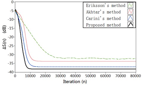
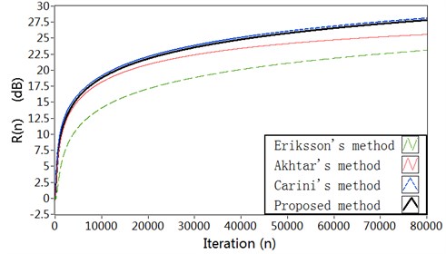
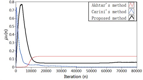
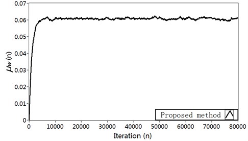
The plots of relative modeling error are shown in Fig. 4(a). It can be seen that the proposed method can decrease the modeling error to a lower level (about –38 dB) at reasonably faster convergence rate comparing with Carini’s method and Akhtar’s method. The results about vibration reduction are shown in Fig. 4(b). It can be shown that the proposed method offers a much better vibration reduction. The variation charts of the step size for secondary path modeling filter are shown in Fig. 4(c). In Akhtar’s method, the step size is set to a fixed value at the start-up and later increased to a fixed value . In proposed method, the step size varied adaptively in accordance with the ratio of the power of the auxiliary noise and that of residual signal . After the start-up of the AVC system, the step size in proposed method increases to a relatively large value resulting in a rapid convergence of the secondary path modeling filter. In the proposed method and Carini’s method, the variation of step size has a decreasing behavior with the converging of the AVC system. That because the variation of step size depends upon the relative modeling error of the secondary path which starts iteration from a unit vector, and then decrease to zero with the converging of the AVC system. The corresponding curve for the step size is shown in Fig. 4(d).
Fig. 4Simulation results in Case 1: a) Modeling error ∆S(n) (dB), b) Vibration reduction R(n) (dB), c) The time-varying step size μs, d) The time-varying step size μw
a)
b)
c)
d)
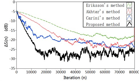
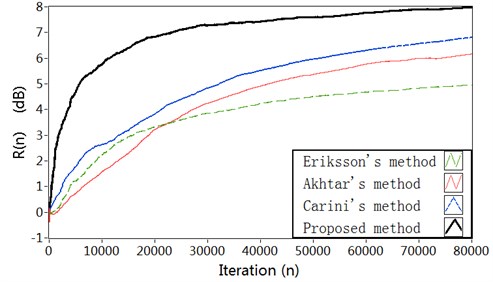
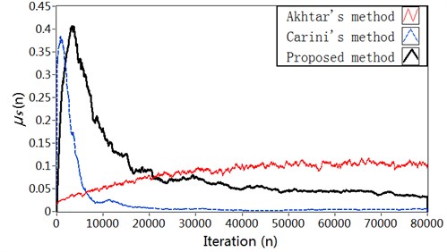
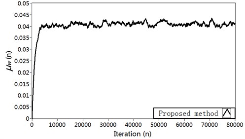
Fig. 5Simulation results in Case 2: a) Modeling error ∆S(n) (dB), b) Vibration reduction R(n) (dB), c) The time-varying step size μs, d) The time-varying step size μw
a)
b)
c)
d)
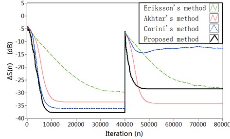
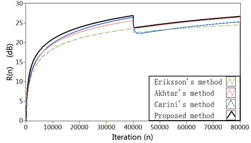
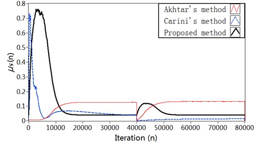
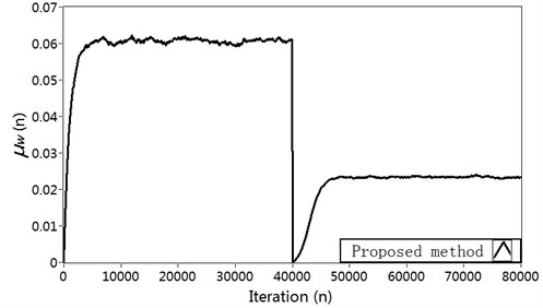
Fig. 6Simulation results in Case 3: a) Modeling error ∆S(n) (dB), b) Vibration reduction R(n) (dB), c) The time-varying step size μs, d) The time-varying step size μw
a)
b)
c)
d)
3.2. Case 2
In Case 2, the reference signal is a broadband vibration signal obtained by filtering a zero-mean white Gaussian noise with band pass filter having pass-band 100-400 Hz. The variance of the reference signal is adjusted to 2. A zero-mean white Gaussian noise of variance 0.1 is used for the secondary path modeling. The parameters have been set as follows: The step size of the active control filter is in all of these methods. The parameters of Eriksson’s method are: . The parameters of Akhtar’s method are: , , , . The parameters of Carini’s method are: , , .
Comparison results of the simulation experiment are shown in Fig. 8. As can be seen, we notice a strong performance improvement with the proposed method in the convergence speed of the algorithm, in the estimation accuracy of the secondary path modeling filter, and in the power of error microphone signal. The simulation results for broadband input show similar superiority as for fixed frequency input in Case 1. The reason is also similar with Case 1.
3.3. Case 3
Studies show the norms of the adaptive filters and are almost not affected by changes in the primary vibration after system convergence. However, they are sensitive to changes in the secondary path or the primary path [8].
In Case 3, we consider both the primary and the secondary paths transfer functions are suddenly changed during operation. The reference signal is same as described in Case 1. The system is started with the same conditions as described for Case 1. In the first 40000 simulation samples we assume to have impulse responses of the primary path and of the secondary path which are the same of the first two set of simulations. A sudden and large variation is introduced to the secondary path at the 40000th sample. The FIR filter coefficients of the primary path and secondary path are shown in Fig. 3.
The results about modeling error for the four methods are shown in Fig. 6(a). As can be seen, the proposed method decreases the modeling error to about –28 dB after the vibration path change, while Akhtar’s method can reduce the modeling error to about –34 dB. So the system equipped with Akhtar’s method gets a smaller modeling error. But the system equipped with proposed method provides a much faster convergence of the SPM filter after the vibration path change. Carini’s method has low tracking capability for the vibration path perturbation, and the convergence of the SPM filter is slow. The results regarding vibration reduction are shown in Fig. 6(b). It can be seen that the proposed method achieves higher vibration reduction as compared with the other three methods. In proposed method, due to the fast convergence of SPM filter, the interference effect of is quickly neutralized from the error signal for the active vibration control filter . The variation charts of the step size for secondary path modeling filter are shown in Fig. 6(c). The corresponding curve for the step size is shown in Fig. 6(d).
4. Active vibration control experimental and results
In this section, an active structure vibration control experiment on helicopter fuselage is provided in order to verify the effect of the proposed online secondary path modeling technology. Reductions in the fuselage vibration result through superposition of the vibrations caused by the actuator control forces with the vibrations caused by the rotor head forces. The AVC experiment strategy is outlined in Fig. 7. At first, a primary source signal used to simulate the rotor hub force is output by the signal generator, and amplified by the power amplifier to the exciter put at the location of the rotor hub. So the helicopter fuselage will keep on vibrating. And then, the acceleration sensor receive the error signal at a controlled position in the fuselage and send them to data acquisition cards through charge amplifier and low-pass filter. The error signal and the reference signal as input signals are sent to adaptive active vibration controller. The magnitude and phase of the controlled force excited by the actuator is calculated to minimize vibration. The control force signal is sent to the secondary actuator through the power amplifier, and act on the helicopter fuselage. In the case, the vibratory response of the fuselage caused by the rotor hub forces is canceled or minimized.
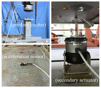
The object of active control experiment is a similar model simplified from a real helicopter. The schematic diagram of the experiment is shown in Fig. 8. A primary exciter is hung with upside down at the location of the rotor hub used to simulate the rotor hub force. A secondary actuator is placed at the bottom of the cockpit in the fuselage. The exciter and actuator are HEV-50 type vibrators from NUAA. An acceleration sensor is placed on the cockpit floor to measure the structure vibration signal. The acceleration sensor is PCB accelerometer. The data acquisition card is NI 9215 which has four channels, and the analog signal generator module is NI 9263 card. The power amplifiers are HEAS-50 power amplifier provided by Nanjing Buddha Technology Company. The charge amplifier is 61012 power supply from B&W Sensing Tech. The control algorithm is implemented on NI Compact RIO Real-Time Controller with FPGA, the type is 9024.
The experiment is based on the National Instruments reconfigurable embedded measurement and control system (NI Compact RIO). The control algorithm is implemented on NI Compact RIO Real-Time Controller with FPGA, the type is 9024. The primary vibration signal is a sine signal with the frequency 20 Hz, the sine signal amplitude is 1 V. The auxiliary noise for the online secondary path modeling is a Gaussian White Noise which is zero mean, and amplitude is 0.1 V. The lengths of active control filter and secondary path modeling filter are 128 and 64, respectively, initial values are zero. . The sampling frequency is chosen to be 1000 Hz.
Fig. 7Active control of structural vibration block diagram
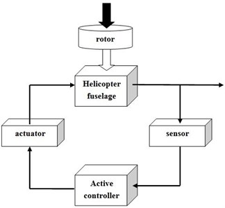
Fig. 8View of the experimental set-up
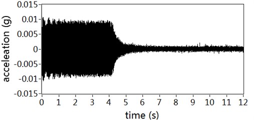
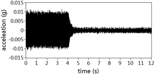
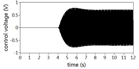
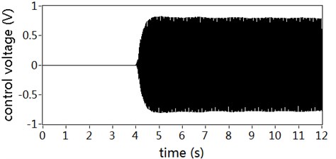
The active controller started working from the second 4. The part of 0 to 4 seconds is the uncontrolled state for structure continuous vibration conditions. Fig. 9 shows the acceleration responses of the selected control positions. It can be seen that the controlled responses reach quickly to the expected level of vibration suppression. The amplitude of the structural residual vibration decreased by about 75 % with no auxiliary noise scheduling, and about 85 % with the proposed auxiliary noise scheduling strategy. The results indicate that the contribution of auxiliary noise to the residual vibration has been reduced almost with the proposed auxiliary noise scheduling strategy, but the rate of convergence declines in a small degree because a large auxiliary noise is good for secondary path modeling accurately.
Fig. 10 shows the control voltages for secondary actuator with auxiliary noise scheduling and not. It can be seen from the figure that the contribution of auxiliary noise to the control voltage has been reduced almost with the proposed auxiliary noise scheduling strategy. If not, the auxiliary noise would superpose in the control voltage and reflect in residual vibration.
Fig. 9Acceleration responses of controlled position: a) With auxiliary noise scheduling, b) With no auxiliary noise scheduling
a)
b)
Fig. 10Control voltages for secondary actuator: a) With auxiliary noise scheduling, b) With no auxiliary noise scheduling
a)
b)
5. Conclusions
This paper has proposed a new active vibration control method with online secondary path modeling. FXLMS algorithm is used to adapt the active control filter. And a modified variable step size LMS algorithm based on delay coefficient technique is used to adapt the modeling filter of the secondary path. A simplified auxiliary noise scheduling strategy is introduced to eliminate the contribution of auxiliary noise on the residual vibration. The simulation results show that the proposed method has the lowest computational complexity and the fastest convergence rate comparing with previous methods. The experimental results verify that the design of the active vibration control system with the proposed method gives much better vibration attenuation and the contribution of auxiliary noise to the residual vibration has been almost attenuated.
References
-
Huang Q. Z., Luo J., Li H. Y., Wang X. H. Analysis and implementation of a structural vibration control algorithm based on an IIR adaptive filter. Smart Materials and Structures, Vol. 22, 2013, p. 085008.
-
Jovanovic M. M., Simonovic A. M., Zoric N. D., Lukic N. S., Stupar S. N., Ilic S. S. Experimental studies on active vibration control of a smart composite beam using a PID controller. Smart Materials and Structures, Vol. 22, 2013, p. 115038.
-
Alkhatib R., Golnaraghi M. F. Active structural vibration control: a review. The Shock and Vibration Digest, Vol. 35, 2003, p. 367-383.
-
Gupta A., Yandamur S., Kuo S. M. Active vibration control of a structure by implementing filtered-X LMS algorithm. Noise Control Engineering Journal, Vol. 54, 2006, p. 396-405.
-
Snyder S. D., Hansen C. H. The effect of transfer function estimation errors on the filtered-x LMS algorithm. IEEE Trans. Signal Process, Vol. 42, 1994, p. 950-953.
-
Saito N., Sone T. Influence of modeling error on noise reduction performance of active noise control systems using filtered-x LMS algorithm. Journal of the Acoustical Society of Japan, Vol. 17, 1996, p. 195-202.
-
Pu Y. X., Zhang F., Jiang J. H. A new online secondary path modeling method for adaptive active structure vibration control. Smart Materials and Structures, Vol. 23, 2014, p. 065015.
-
Eriksson L. J., Allie M. C. Use of random noise for online transducer modeling in an adaptive active attenuation system. The Journal of the Acoustical Society of America, Vol. 85, 1989, p. 797-802.
-
Zhang M., Lan H., Ser W. Cross-updated active noise control system with online secondary path modeling. IEEE Transactions on Speech and Audio Processing, Vol. 9, 2001, p. 598-602.
-
Zhang M., Lan H., Ser W. A robust online secondary path modeling method with auxiliary noise power scheduling strategy and norm constraint manipulation. IEEE Transactions on Speech and Audio Processing, Vol. 11, 2003, p. 45-53.
-
Akhtar M. T., Abe M., Kawamata M. A new variable step size LMS algorithm-based method for improved online secondary path modeling in active noise control systems. IEEE Transactions on Audio Speech and Language Processing, Vol. 14, 2006, p. 720-726.
-
Akhtar M. T., Abe M., Kawamata M. Noise power scheduling in active noise control systems with online secondary path modeling. IEICE Electronics Express, Vol. 4, 2007, p. 66-71.
-
Carini A., Malatini S. Optimal variable step-size NLMS algorithms with auxiliary noise power scheduling for feedforward active noise control. IEEE Transactions on Audio Speech and Language Processing, Vol. 16, 2008, p. 1383-1395.
-
Andreas Mader, Henning Puder, Gerhard Uwe Schmidt Step-size control for acoustic echo cancellation filters – an overview. Signal Processing, Vol. 80, 2000, p. 1697-1719.
About this article
This research is supported by the National Natural Science Foundation of China (No. 51305197), Aeronautical Science Foundation of China (No. 2012ZA52001), Research Fund for the Doctoral Program of Higher Education of China (No. 20123218120005) and A Project Funded by the Priority Academic Program Development of Jiangsu Higher Education Institutions.
