Abstract
The purpose of this paper is to propose an alternative approach on controlling of vehicle vibrations by using active tuned mass damper. The approach is presented by simulation of a quarter-car model. Initially, a tuned mass damper is integrated on a vehicle model and its optimal parameters are determined by using 3D diagram of the maximum magnitudes of the sprung mass frequency response functions. Active control is obtained by adding an actuator element parallel to tuned mass damper. The fuzzy-sliding mode control method is utilized in reducing the displacement and acceleration magnitudes of sprung mass. Finally, comparison of active and passive responses in frequency and time domain are given to demonstrate vibration control improvement.
1. Introduction
Traditionally, vehicle vibrations are controlled by passive suspension systems. A passive suspension system consists of spring and damper elements and it is generally located between wheel-axle and vehicle body. This system provides the reduction of vibration effects subjected to dynamic forces within the trade-off relation between the ride comfort and road holding. Although the trade-off issue of passive suspension system is mostly overcome by active and semi-active suspension systems, the control of vehicle vibrations still keeps the interest of research and development both in academia and industry. Cherry and Jones [1] had demonstrated the application of fuzzy logic techniques to the control of automotive suspension system in order to reduce the traditional compromise between the different requirements of the suspension system. Kim and Ro [2] had developed a robust control scheme for an active suspension system. They had shown that both the ride quality and handling performance are improved using the sliding mode active suspension system in the presence of non-linearities of the suspension system and uncertainties of suspension parameters. Recently, Arslan et al. [3] had applied classical and fuzzy tuned sliding mode controllers to a human-vehicle model in order to improve the ride comfort. In another recent study, van der Sande et al. [4] had developed a robust controller for an electromagnetic suspension system using a quarter car model.
The tuned mass damper (TMD) and dynamic vibration absorber (DVA) are widely used devices for suppressing vibration level of various structures such as ships, wires, bridges, buildings, etc. [5, 6]. While DVA consists of a spring element and a mass, TMD is a damped DVA which is obtained by adding a damper element parallel to DVA. It has been well-known by Frahm who was the inventor and the first patent owner of a DVA design in the early 1900s [7]. Traditional DVA and TMD have a narrow-band nature and contain a potential that can be improved by adding an actuator in order to compose the active dynamic vibration absorber (ADVA) and active tuned mass damper (ATMD). This device includes a potential to be used as a vibration absorber in vehicle suspension system. In a technical paper, common TMD applications in automobiles are listed as crankshaft, axle pinion nose, exhaust system, etc. [8]. In Hrovat’s survey paper [9] about advanced suspension developments, the use of TMD as a dynamic vibration absorber which was attached to the unsprung mass was reviewed. The main contribution of the actual study is the demonstration of the use and application of an ATMD to a vehicle model in order to suppress undesired vibration effects by simulation results. There were several ATMD and TMD investigations realized for various applications rather than vehicle suspensions. For instance, Yagiz [10] had developed a sliding mode controller for suppressing earthquake or wind induced vibration of a multi-degree-of-freedom structure. Pourzeynali et al. [11] had presented a combined application of genetic algorithms and fuzzy logic controller. They had showed that integration of the fuzzy logic and genetic algorithms resulted in better performance of the ATMD system in terms of response reduction. Hacioglu and Yagiz [12] had presented an adaptive backstepping controller with estimation for uncertain systems with an application to a nine-story building model where an ATMD was installed on the top floor as a dynamic absorber. Kahya and Araz [13] had demonstrated the effectiveness of the series multiple tuned mass dampers (STMD) in bridge vibration suppression. Another TMD system was proposed using modal FRF by Debnath et al. [14] to control truss bridge vibrations.
In this study, an ATMD attached to the sprung mass of vehicle, is proposed as an alternative approach for the control of vehicle vibrations. The quarter car model which has been proved to be useful for designing control strategies for active suspension system [15-18], is chosen for the investigation of ATMD in vehicle suspension system reducing the sprung mass vibrations and improving the passenger ride comfort. In the following sections, use of ATMD is explained under the topics of active tuned mass damper on a quarter-car model, determination of optimum parameters of TMD, fuzzy-sliding mode controller for ATMD with numerical results and conclusion, respectively.
2. Active tuned mass damper on a quarter-car model
A quarter-car model with a traditional passive suspension system is shown in Fig. 1(a). In this model, m1 represents unsprung mass and m2 represents sprung mass. k1, k2 and b2 denote stiffness coefficient of wheel, stiffness and damping coefficients of passive suspension system respectively. In Fig. 1(b), additional mass m3 is connected to sprung mass with spring and damper elements to form a TMD. k3 and b3 are stiffness and damping coefficients of TMD, respectively.
Fig. 1Quarter-car model with a) passive suspension, b) TMD, c) ATMD
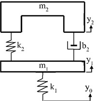
a)
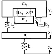
b)
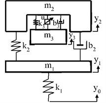
c)
ATMD is constituted by adding an actuator to the TMD and can be investigated as an alternative active vibration controller as shown in Fig. 1(c). u is the controller force of actuator generated by control algorithm. y0, y1, y2 and y3 are absolute vertical displacements of road profile, unsprung, sprung and ATMD masses respectively.
Equation of motion of the quarter-car model with ATMD can be obtained by Newton’s second law of motion and are given below:
Numerical parameters of the quarter-car model are listed in Table 1.
Active and passive cases of TMD should be evaluated separately. In active case, there are four parameters acting on the system response which are ATMD mass (m3), ATMD spring coefficient (k3), ATMD damper coefficient (b3) and actuator force (u). TMD and ATMD mass have chosen constant and same for both cases given in Table 1. The other TMD parameters k3 and b3 were obtained for optimum conditions explained in the next section. When these parameters were utilized in active case, the displacement of the ATMD mass could have exceeded the psychical limits of suspension working space. Therefore, for active case, these parameters were chosen by using trial and error, in order to preserve these limits.
Table 1Numerical parameters of the quarter-car model
Parameters | Passive | TMD | ATMD | |
m1 | (kg) | 56.5 | 56.5 | 56.5 |
m2 | (kg) | 277.16 | 277.16 | 277.16 |
m3 | (kg) | – | 27.716 | 27.716 |
k1 | (N/m) | 211180 | 211180 | 211180 |
k2 | (N/m) | 27000 | 27000 | 27000 |
k3 | (N/m) | – | 1500 | 10000 |
b2 | (N·s/m) | 1750 | 1750 | 1750 |
b3 | (N·s/m) | – | 90 | 4000 |
3. Determination of optimum parameters of TMD
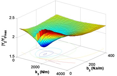
TMD consists of three parameters seen in Fig. 1(b) that are TMD mass, spring and damper coefficients. The optimum parameters of TMD are obtained for the minimum sprung mass displacement condition that provides riding comfort quality. The frequency response function (FRF) of the sprung mass is used to determine the ratio between the sprung mass displacement and road displacement in the frequency band is given in Appendix A1. First of all, TMD mass is chosen. Then spring and damper coefficients are varied to calculate each FRF. The maximum magnitude of each FRF is plotted on 3D diagram. The maximum magnitudes of FRF versus various spring and damper coefficients generate a surface that can be utilized to supply optimum criteria. There exists a minimum of maximums which gives the optimum spring and damper coefficients of TMD for the former condition. In this study TMD mass is taken as one of tenth of sprung mass (m3=m2/10) and the other two parameters are varied to generate a 3D diagram of the maximum magnitudes of the sprung mass FRF versus spring and damper coefficients that can be seen in Fig. 2. The minimum of maximums is occurred when the spring coefficient is taken between 1000 N/m and 2000 N/m, and the damper coefficient is taken between 0 and 200 N.s/m. The frequency response function and calculated optimum spring and damper coefficients for TMD are given with numerical parameters in Table 1.
Fig. 2Optimum parameter determination of TMD; variation of Y2/Y0max for different k3 and b3 values
4. Fuzzy-sliding mode controller for ATMD
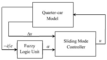
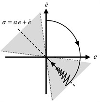
In this section, a fuzzy-sliding mode controller [19] utilized for ATMD is described. Fuzzy sliding mode controller (FSMC) includes the combination of a sliding mode controller (SMC) and a fuzzy logic unit that tunes the sliding surface slope of the SMC shown in Fig. 3(a). The main idea of this controller is to force the sliding surface to catch state errors and make them zero more rapidly rather than waiting the state errors to reach to sliding surface. A representation of the fuzzy-sliding surface is shown in Fig. 3(b). Sliding surface slope changes dynamically inside the gray colored area in order to catch error and time derivative of error and force them to reach zero on sliding surface rapidly.
Fig. 3a) Block diagram of the FSMC, b) Fuzzy-Sliding surface representation
a)
b)
The concept of sliding mode control (SMC) has been occurred as the results of researches in the former Soviet Union at the end of 1950’s [20]. The state space equation of the system can be defined as:
The state vector x represents the displacements and their corresponding velocities respectively. f(x,t) is the vector of the equations of the system without the control inputs. u is the vector of the control forces. B is the input matrix. The related vectors and matrix can be obtained from Eqs. (1-3) for ATMD and given in Appendix A2.
The aim of the controller is to control the variable x under the system uncertainties and hold the system on a sliding surface. The sliding surface equation for a control system can be selected as follows:
Δx is the difference between the reference value and the system response. G is the matrix, which includes the sliding surface slope. If G and Δx are written below:
Then, sliding surface can be written as in Eq. (7) which is shown in Fig. 3(b):
α is the slope constant being positive and represents the negative value of the sliding surface slope. A stable and non-chattering controller force (u) can be obtained for ATMD as in [10]:
where Γ is assumed to be the constant positive matrix in order to induce the system to follow the constraints by holding it on the surface. An average of the total control force can be preferred for the equivalent control force by designing an averaging filter for the estimation of the equivalent control force [19]:
The logic behind the design of a low-pass filter is that high frequencies come from unmodeled dynamics and low frequencies determine the characteristics of the signal.
In order to obtain FSMC, the input variable of the fuzzy logic part of the controller is chosen as the negative value of the derivative of error per error (-˙e/e) of the controlled state and the output variable as the slope constant α shown in Fig. 3(a). For the fuzzification of the input and output variables, the triangular membership functions are utilised as shown in Fig. 4. While Pi (i= 1, 2,…, 7) denotes positive membership functions of the input variable, N and Z represent negative and zero, respectively. Furthermore, Ai (i=1, 2,…, 9) stand for the membership functions which are all positive for the output variable. In order to avoid the use of large values by the fuzzy logic unit, the input value is limited by appropriate bounds. Input and output variables are scaled by scaling factors SF-˙e/e and SFα, respectively. The fuzzy associative memory (FAM) table is given in Table 2.
Fig. 4Membership functions for the input and output variables
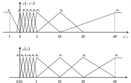
Table 2FAM table for the slope constant
-˙e/e | N | Z | P1 | P2 | P3 | P4 | P5 | P6 | P7 |
α | A1 | A2 | A3 | A4 | A5 | A6 | A7 | A8 | A9 |
The reference variables are chosen as the low pass filtered displacement and velocity of unsprung mass in order to obtain the estimation of road profile and its derivative, since it is difficult to measure the road profile accurately and to obtain its derivative as well. Also, this procedure decreases the need of road profile measurement system and lowers the cost of acquisition system. Controller references and numerical parameters of FSMC for ATMD are given in Table 3.
Table 3Controller references and numerical parameters of Fuzzy SMC for ATMD
Controller references | Controller parameters | |
y2ref=1τrefs+1y1 | τ= 0.05 | Γ= 60 |
dy2refdt=1τdrefs+1dy1dt | τref= 0.15 | SF-˙e/e= 0.001 |
τdref= 0.08 | SFα= 1 | |
5. Numerical results
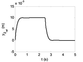
In this section, the results of ATMD application is presented by time and frequency responses of a quarter-car model simulation. A road profile seen in Fig. 5 is used to obtain time responses. Vehicle model travels at a constant speed of 20 m/s over the road profile. Initially, it reaches up to 0.01 m height and 0.01 m long ramp, then passes 50 m on the straight road. Afterwards it reaches down to ground level from the same symmetric ramp.
During the vehicle travel over the road profile, the road induced vehicle body vibrations are compensated by actuator using ATMD working space. During control action, if absolute zero reference is assigned to the vertical motion of the vehicle body, it will degenerate ATMD working space or cause it to reach to the working limits. Therefore, to preserve the ATMD working space, it is assumed the reference values for the vertical motion of the vehicle body to be equal to the filtered values of displacements and velocities of the unsprung mass [20]. The reference of sprung mass for given road profile is given in Fig. 6.
Fig. 5Road profile
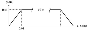
Fig. 6The reference of sprung mass for the selected road
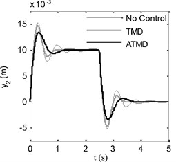
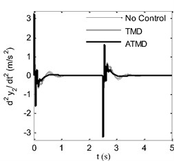
In Fig. 7, ride comfort can be evaluated through time diagrams of displacement and acceleration of sprung mass during vehicle travel over the road profile. In Fig. 7(a), displacement of sprung mass is compared between TMD, ATMD and passive suspension system. It is seen that during the vibration of sprung mass, kinetic energy is lost in two and a half periods with passive suspension system and TMD case. On the other hand, in ATMD application, it is ended only in one period. Additionally, overshoot is reduced by 11 % approximately compared with no control case. Similar results are observed for acceleration diagram in Fig. 7(b). Acceleration values go to zero faster in ATMD case if they are compared with passive suspension system and TMD.
Fig. 7Time response comparison of sprung mass: a) displacement, b) acceleration
a)
b)
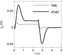
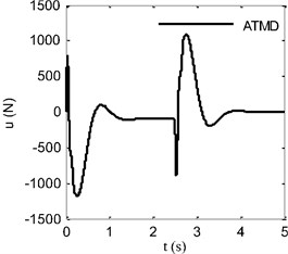
Control force produced by fuzzy-sliding mode controller is shown in Fig. 8(b). As a result of the control action, the forced vibration of ATMD mass and motion of TMD mass are demonstrated in Fig. 8(a). Of course, there are possibilities to limit displacement of ATMD mass by compromising the success of proposed method.
Fig. 8Time response of a) displacement of ATMD mass, b) control force
a)
b)
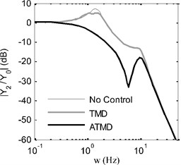
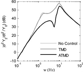
In Fig. 9, displacement and acceleration frequency response functions of sprung mass are compared between passive suspension system which is indicated as “No Control”, TMD and ATMD cases. It is clearly seen that displacement and acceleration magnitudes of sprung mass are suppressed along a broadband for ATMD case when all frequency responses are examined. The suppressed frequency bands vary between 0.25 Hz and 25 Hz for displacement frequency response and 0.35 Hz and 30 Hz for acceleration frequency response. Above mentioned frequency bands include resonance frequencies of sprung and unsprung masses which are about 1 Hz and 10 Hz respectively. It is also seen that TMD case has influence upon a very narrow frequency band that is as expected and improved by active control in ATMD case.
Fig. 9Frequency responses of sprung mass: a) displacement, b) acceleration
a)
b)
6. Conclusions
In this paper, an active tuned mass damper is proposed for vibration control of vehicles and presented by quarter-car model simulation. Although the assembly of an ATMD system on a traditional suspension system seems to be unfeasible, the idea of using an ATMD system involves a potential on vehicle vibration control and ride comfort improvement that is demonstrated by frequency and time response diagrams of sprung mass. It is seen that the displacement and acceleration magnitudes of sprung mass are suppressed over a broad frequency band including resonance frequencies of sprung and unsprung masses with the compromise of ATMD mass motion. Additionally, an experimental study is considered for future work using performance criteria since promising results are obtained from time response diagrams of the sprung mass displacement and acceleration.
References
-
Cherry A. S., Jones R. P. Fuzzy logic control of an automotive suspension system. IEE Proceedings – Control Theory and Applications, Vol. 142, Issue 2, 1995, p. 149-160.
-
Kim C., Ro P. I. A Sliding mode controller for vehicle active suspension systems with non-linearities. Proceedings of the Institution of Mechanical Engineers, Vol. 212, 1998, p. 79-92.
-
Arslan Y. Z., Sezgin A., Yagiz N. Improving the ride comfort of vehicle passenger using fuzzy sliding mode controller. Journal of Vibration and Control, Vol. 21, 2015, p. 1667-1679.
-
van der Sande T. P. J, Gysen B., Besselink I., Paulides J., Lomonova E. A., Nijmeijer H. Robust control of an electromagnetic active suspension system: simulations and measurements. Mechatronics, Vol. 23, Issue 2, 2013, p. 204-212.
-
Wang J. F., Lin C. C., Chen B. L. Vibration suppression for high-speed railway bridges using tuned mass dampers. International Journal of Solids and Structures, Vol. 40, 2003, p. 465-491.
-
Bonsel J. H., Fey R. H. B., Nijmeijer H. Application of a dynamic vibration absorber to a piecewise linear beam system. Nonlinear Dynamics, Vol. 37, 2004, p. 227-243.
-
Korenev B. G., Reznikov L. M. Dynamic Vibration Absorbers: Theory and Technical Applications. John Wiley and Sons, New York, 1993.
-
Aubert A., Howle A. Design issues in the use of elastomers in automotive tuned mass dampers. Technical Paper, SAE International, 2007.
-
Hrovat D. Survey of advanced suspension developments and related optimal control applications. Automatica, Vol. 33, Issue 10, 1997, p. 1781-1817.
-
Yagiz N. Sliding mode control of a multi-degree-of-freedom structural system with active tuned mass damper. Turkish Journal of Engineering and Environmental Science, Vol. 25, 2001, p. 651-657.
-
Pourzeynali S., Lavasani H. H., Modarayi A. H. Active control of high rise building structures using fuzzy logic and genetic algorithms. Engineering Structures, Vol. 29, 2007, p. 346-357.
-
Hacioglu Y., Yagiz N. Adaptive backstepping control with estimation for the vibration isolation of buildings. Journal of Vibration and Control, Vol. 18, Issue 13, 2012, p. 1996-2005.
-
Kahya V., Araz O. Series tuned mass dampers in train-induced vibration control of railway bridges. Structural Engineering and Mechanics, Vol. 61, Issue 4, 2017, p. 453-461.
-
Debnath N., Deb S. K., Dutta A. Multi-modal vibration control of truss bridges with tuned mass dampers under general loading. Journal of Vibration and Control, Vol. 22, Issue 20, 2016, p. 4121-4140.
-
Ozer H. O., Hacioglu Y., Yagiz N. High order sliding mode control with estimation for vehicle active suspensions. Transactions of the Institute of Measurement and Control, 2017, http://doi.org/10.1177/0142331216685394.
-
Taskin Y., Hacioglu Y., Yagiz N. The use of fuzzy-logic control to improve the ride comfort of vehicles. Strojniski vestnik – Journal of Mechanical Engineering, Vol. 53, Issue 4, 2007, p. 233-240.
-
Chen S. A., Wang J. C., Yao M., Kim Y. B. Improved optimal sliding mode control for a non-linear vehicle active suspension system. Journal of Sound and Vibration, Vol. 395, 2017, p. 1-25.
-
Sam Y. Md., Osman J. H. S., Ghani M. R. A. A class of proportional-integral sliding mode control with application to active suspension system. Systems and Control Letters, Vol. 51, 2004, p. 217-223.
-
Yagiz N., Hacioglu Y., Taskin Y. Fuzzy sliding-mode control of active suspensions. IEEE Transactions on Industrial Electronics, Vol. 55, 2008, p. 3883-3890.
-
Utkin V. I. Variable structure systems with sliding modes. IEEE Transactions on Automatic Control, Vol. 22, Issue 2, 1977, p. 212-222.
-
Ertugrul M., Kaynak O., Sabanovic A. A comparison of various VSS techniques on the control of automated guided vehicles. IEEE International Symposium on Industrial Electronics, Athens, Greece, 1995, p. 837-842.
-
Yagiz N., Sakman L. E. Robust sliding mode control of a full vehicle without suspension gap loss. Journal of Vibration and Control, Vol. 11, Issue 11, 2005, p. 1357-1374.

