Abstract
As a novel underwater exploration robot, BYSQ-2 spherical robot uses the heavy pendulum to change the attitudes with the characteristics of small steering resistance and high compressive strength. However, the greater water resistance in the process of moving forward obstructs the rapid movement, because the robot has a spherical shell and only one propeller. The maximum speed was obtained only 0.6 m/s according to experimental tests and theoretical calculations. In order to improve the movement speed, the robot’s virtual assembly model was built to study the coupling hydrodynamic forces between the spherical shell and the propeller by CFD method. The coupling hydrodynamic forces were analyzed and summarized under different key structural parameters that include the pipe diameter and the shell diameter. Furthermore, in the conditions of different rotational speed, propeller thrust and water resistance of robot were simulated and calculated. According to the simulation results of the model with the appropriate structural parameters, it was demonstrated that the speed of the robot was improved obviously in the process of moving forward.
1. Introduction
In recent year, the micro miniature underwater robot, as a type of intelligent mobile vehicle platform for ocean exploration, has been paid more attention and developed rapidly. In the scientific field, underwater robot can be used to explore ocean and gather samples. Moreover, in the military field underwater robot can also be used to assist communication and investigation [1-2].
In general, the shell structure of underwater robot mainly includes three types. One is the cylindrical structure underwater robot, which was remade from the torpedo, which can move fast, but the posture adjustment is difficult at the low speed [3-5]. Another is the well-catalogued underwater robot, which was installed with multiple propellers, and can change attitudes flexibly, but manufacturing cost is high and the efficiency is low [6-8]. Spherical robot was also studied by many institutions, which has a small steering resistance and high compressive capacity underwater, but the water resistance is big and the velocity is low in the process of moving forward [9-12].
At present, because spherical robot has a characteristic of flexible movement, varieties of spherical robots have been developed and can adapt to different environments. Qiang Z. designed an exploration spherical robot that can roll on land [13]. Hanxu S. designed a exploration spherical robot that can fly in the air [14]. Guo S. developed a vectored water-jet based spherical underwater vehicle [15]. A novel spherical underwater robot BYSQ-2 was developed to collect underwater data by Xiaojuan L., which used the heavy pendulum to change the attitudes with the characteristics of small steering resistance, high compressive strength, flexible movement and low cost, so it was very suitable for movement under deep water as an exploration mobile carrier [16]. But the robot has only one propeller and the velocity is low, so it is very difficult to ensure that the robot can successfully complete scheduled tasks in a wide water range within the period of predetermined time. Therefore, it is significant to improve the speed of the robot. This paper studied and analyzed the hydrodynamic characteristics of the spherical robot, especially summarized the coupling laws between the propeller and spherical shell under different structural parameters.
The methods for getting underwater robot’s hydrodynamic data mainly consist of experiment test, theoretical calculation and CFD simulation [17-20]. Experimental method takes a long period and high cost, and only limited measure results can be got, even some need complex data processing. Calculation method needs to solve fluid equations or engineering experience formulas that not only is low accuracy, but also it is not comprehensive [21, 22]. With the development of computing technology, CFD simulation technology has been widely used to study fluid dynamics problems, which taks short cycle, low-cost, fully solver and the guaranteed accuracy [23-25]. Therefore, in the absence of sufficient experimental conditions, it is undoubtedly a simple and effective method to analyze the robot’s hydrodynamic characteristics by CFD simulation.
This paper is organized as follows. In Section 2, the robot’s physical prototype is introduced, and the maximum speed is tested by experiment. In Section 3, on the basis of verifying the reliability of the simulation, the robot’s finite element model is established and simulated. In Section 4, under the conditions of different structural parameters, hydrodynamic coupling characteristics are analyzed, and the optimal parameters are determined. In Section 5 the important conclusions are drawn, and some arranges are mentioned for future research.
2. Physical prototype and experiment
BYSQ-2 spherical robot mainly consists of spherical shell 1, pipe 2, propeller 3, pendulum 4 and pitching axis 5. Driven by a motor, the weight pendulum can swing around the pitching axis and change the center of gravity of the robot, and then the generated torque can adjust the pitching angle of the robot. Meanwhile, driven by another motor, the weight pendulum can rotate around the pipe and make the robot roll. The pipe is fixed to the shell and the propeller is mounted inside the pipe. The direction of the propeller can change depending on the robot’s posture and the propeller provides the thrust to make the robot move forward. Physical prototype of robot is shown in Fig. 1.
Fig. 1Physical prototype of the robot
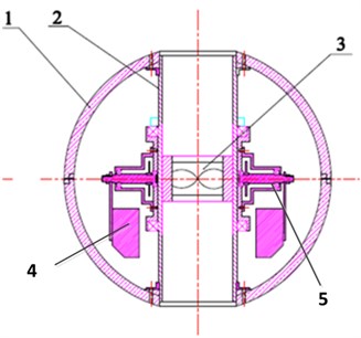
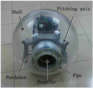
This kind of small spherical robot has a great advantage on the deep-water exploration. Firstly, the steering resistance is low and the attitude can be changed flexibly. Secondly, the spherical shell can resist greater pressure and be sealed easily to protect the internal electronic components. Thirdly, because of spherical symmetric structure, the robot can be controlled flexibly at a low speed. But this type of spherical robot also has a drawback that the spherical shell generates the greater water resistance so that the robot moves forward slowly. The movement resistance of underwater objects include friction and pressure, but in the actual calculation and application they are often merged together as the hydrodynamic drag, and the functional relationship can be expressed as Eq. (1):
where CD is the drag coefficient of the object, ρ is the density of water, v is the forward speed of the object, A is the cross-sectional area of the object.
According to Dallavalle’s conclusion, if Reynolds satisfies 1<Re<2×10⁵, the fluid resistance coefficient of three-dimensional spherical body can be expressed as Eq. (2):
Propeller’s thrust is expressed as Eq. (3):
where KT is the propeller’s thrust coefficient, n is the propeller’s rotational speed, Dp is the diameter of the propeller.
According to Newton's law:
where m is the robot’s mass; λ is the added mass of water.
From Eqs. (1)-(3), the translational movement equation of the robot can be derived as Eq. (5):
When the robot reaches the maximum velocity, the maximum speed of the robot can be expressed as Eq. (6):
Fig. 2Experiment of the robot prototype
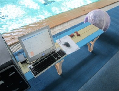
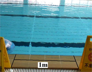
An experiment was implemented in the pool as shown in Fig. 2, and the maximum speed of the robot was measured. After the speed reached the maximum, the time period of the robot moving through 1m distance was recorded, and the average speed was calculated. The test data is shown in Table 1. The spherical underwater robot’s maximum speed can be obtained 0.656 m/s by the experimental data and calculated results, which is slightly larger than the calculation results. And the hydrodynamic calculation is an important factor.
Table 1Test data of maximum speed experiment
Cycle | 1 | 2 | 3 | 4 | 5 |
Time (s) | 1.53 | 1.53 | 1.55 | 1.55 | 1.52 |
Test velocity (m/s) | 0.654 | 0.654 | 0.645 | 0.645 | 0.658 |
Computational result (m/s) | 0.580 | 0.580 | 0.580 | 0.580 | 0.580 |
3. Finite element model and coupling simulation
CFD finite element method uses a numerical method to solve the problem of viscous flow, and Navier-Stokes equations need to be processed by time averaging. But the equation is not closed, and then a turbulence equations need to be introduced to assist solving. Currently, the k-ε standard is used widely, and the mathematical expression of the turbulent kinetic energy equation is shown as Eq. (7):
Turbulent dissipation rate equation is shown as Eq. (8):
where Gk is an energy item about the average gradient; Gb is the energy item about the buoyancy; YM is the pulsating diffusion item; C1κ, C2κ and C3κ are the empirical constants; σk and σκ are Prandtl constants kinetic that related with energy k and dissipation rate ε; Sk and Sκ are defined as the source terms.
To verify the validity of the simulation method, the robot is simplified into a sphere of 500 mm diameter that moves forward at different speeds underwater. In the CFD simulation model, the inlet velocity of the fluid domain is set to be the movement speed of the robot, and the pressure outlet boundary is set to be 0 Pa. Other boundaries of the fluid domain are set to be symmetry, and the default parameters of k-ε viscosity model are chosen to simulate. Meanwhile the resistance of the ball is calculated according to the Eq. (6). As shown in Table 2, it can be obtained that the simulation results of the resistance are consistent with the theoretical values, which are closely related to the magnitude of the velocity of the sphere.
Table 2Data of the sphere resistance
Velocity (m/s) | 0.25 | 0.50 | 0.75 | 1.00 | 1.25 |
Simulation resistance (N) | 2.4 | 9.8 | 21.4 | 38.1 | 60.1 |
Calculation resistance (N) | 2.6 | 9.9 | 21.7 | 38.6 | 60.4 |
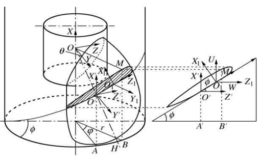
The simple sphere model above is not an accurate representation for the hydrodynamic simulation of the sphere robot, because the pipe and propeller are installed in the middle of the robot. The working state of the propeller can affect the fluid pressure distribution around the robot, so the robot can’t be regarded as a three-dimensional sphere and the hydrodynamic simulation requires a more accurate finite element model. A CFD model with a propeller is necessary to analyze the coupling hydrodynamic forces. The three-dimensional model of the propeller can be built based on the principle of conversion relationship from two-dimension to three-dimension. Fig. 3(a) shows the principle of the projection of the propeller. In the global coordinate system OXYZ, OYZ plane is parallel to the end surface of the propeller boss. O' is the intersection point between the reference line OH and the cylindrical surface. The O1X1 axis of the coordinate system O1X1Y1Z1 cross over the thickest section of the blade. O1 point is the tangent point of the spiral line and the blade section. The coordinate system O1UVW is parallel to the coordinate system of O'X'Y'Z'. The conversion relationship between the coordinate systems is expressed as shown in Eq. (9):
where ϕ is the pitch angle; L is the distance from the maximum thickness to the reference line; r is the radius of blade section; θ is the angle of rake.
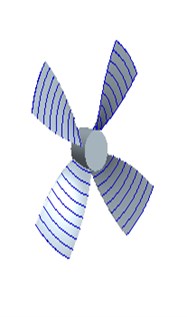
Fig. 3Model and projection principle of the propeller
a)
b)
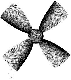
Propeller diameter is 108 mm; the ratio of the blade area is 0.5; the ratio of boss diameter is 0.18; the average ratio of blade pitch is 1.172. Firstly, the two-dimensional data points are computed by Matlab, then these values are converted into a three-dimensional coordinate system according to Eq. (9). A three-dimensional model of propeller is established, according to surface modeling method by Pro/E as shown in Fig. 3(b). The open water data of propeller from simulation and experiment is shown in Table 3.
Table 3Open water data of propeller
Advance ratio | 0.1 | 0.2 | 0.3 | 0.4 | 0.5 |
Simulation thrust coefficient | 4.1 | 3.7 | 2.4 | 1.8 | 0.6 |
Experiment thrust coefficient | 4.2 | 3.6 | 2.3 | 1.7 | 0.7 |
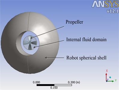
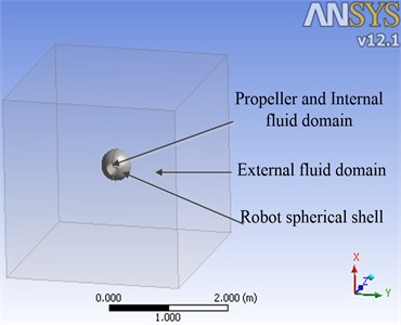
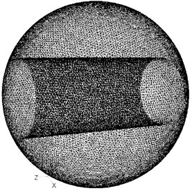
According to the characteristics of spherical shell, the robot is simplified into a pipe-sphere model, and the maximum diameter of sphere D is 0.5 m. A cube of 3 m side length is built as the external fluid domain, and the robot model locates in the center of the cube. A cylindrical internal fluid domain is also built to contain the propeller and its diameter d is 0.12 m. The assembly model and finite element mesh model of the spherical robot are shown in Fig. 4.
Fig. 4Assembly and mesh model for CFD
a)
b)
c)
d)
Fig. 5Coupling hydrodynamic simulation
a)
b)

c)
Fig. 6Influence of the key structural parameters

a)
b)
c)

d)
e)
f)
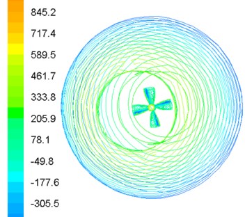
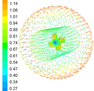
The actual velocity of the robot is less than 0.65 m/s based on the experimental results. To improve the movement speed of the robot, the coupling hydrodynamic of the robot is simulated under 1 m/s conditions. Assembly model of the robot locates in the center of the external fluid domain where the motion type is stationary. Inlet velocity v of external fluid domain is 1 m/s, and outlet pressure is 0 Pa. The internal fluid domain rotates with the propeller rotating where the motion type is moving reference frame. The interface is set to pass data between internal fluid domain and external fluid domain, and the boundary type of propeller and shell is set as wall. Under the propeller rotation speed n=600 rpm, the simulation results of the robot are shown in Fig. 5.
As can be seen from the simulation result in Fig. 5, the water pressure is large in the front and rear of the robot, while the pressure of side surface is small. However, the flow velocity distribution shows the opposite tendency in Fig. 5(b). The water pressure is also small in the front and rear of the propeller Fig. 5(c). Spherical shell resistance is equal to the pressure difference between the front and the rear, and the propeller thrust is the opposite direction of the spherical shell resistance. In such structure and motion parameters, propeller thrust is smaller than the shell resistance, so the robot cannot reach the speed of 1 m/s.
4. Analysis of key structural parameters
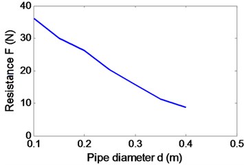
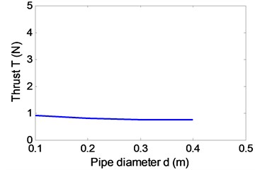
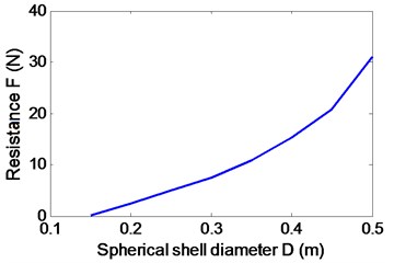
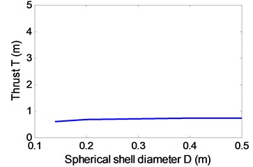
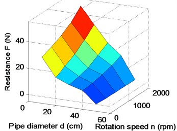
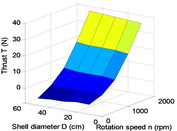
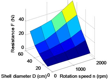
The forward speed of the robot is mainly determined by the resistance of shell and the thrust of the propeller. Because the propeller is mounted inside the pipe, the ability of its propulsion is not only related to the structure itself, but also is affected by the structural parameters of the spherical shell. In addition, the resistance is also affected by the propeller’s working state, so the hydrodynamic parameters of resistance and thrust couple and interact with each other. Paper analyzes and summarized the impact of pipe diameter d, spherical diameter D and propeller rotation speed n on coupling hydrodynamic forces of robot by CFD simulation. Under the conditions of v= 1 m/s, D= 0.5 m, n= 600 rpm and d from 0.1 m to 0.4 m, the simulation results show that the shell resistance is reduced greatly, and thrust little change in Fig. 6(a)-(c). Under the conditions of v=1 m/s, d=1.4 m, n= 600 rpm and D from 0.14 m to 0.5 m, the simulation results show that the shell resistance is increased greatly, and thrust little change in Fig. 6(d)-(f).
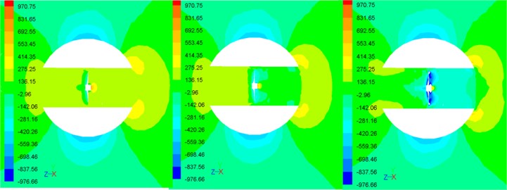
As shown in Fig. 6, the propeller thrust substantially contains unchanged, so the resistance of the robot can be reduced by decreasing the shell diameter and increasing the pipe diameter. Under the conditions of v=1 m/s, d=0.14 m, D=0.35 m and n from 0 to 2000 rpm, the hydrodynamic forces are simulated as shown in Fig. 7.
Fig. 7Influence of the speed parameters
a)
b)
c)
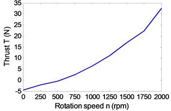
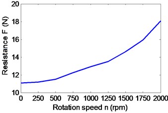
As shown in Fig. 7(a), with the propeller speed increasing, the pressure in front of the robot substantially contains unchanged, but that in the front of propeller and the rear of robot gradually becomes smaller. Meanwhile both the shell resistance and the propeller thrust are increased greatly in Fig. 7(b) and (c).
Fig. 8Analysis of the key parameters
a)
b)
c)
d)
e)
f)
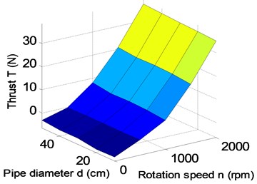
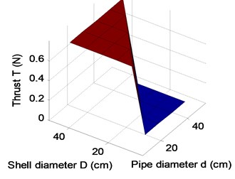
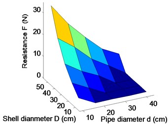
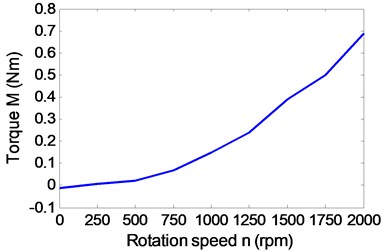
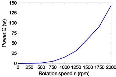
After a lot of simulations, the influences of pipe diameter, spherical shell diameter and propeller peed on thrust and drag of the robot are shown in Fig. 8. It can be obtained that the propeller speed mainly affects the thrust of the robot in Fig. 8(a), (c) and (e). Fig. 8(b), (d) and (f) show that the resistance is not only related to the speed, but also is related to the structural parameters of the robot. In Fig. 8(e) and (f), it can be seen that the thrust is greater than the resistance at a certain propeller speed, when the structural parameters are chosen reasonably. The propeller needs to be put into the pipe, so the pipe diameter can’t be too small. Similarly, the internal heavy pendulum structure also needs to be wrapped and protected by the spherical shell, so the sphere shell of the robot can’t also be too small. Therefore, keeping the sizes of the propeller and the pendulum of robot as a constant, pipe diameter is d>10 cm, d<D and sphere diameter D>30 cm. A group of parameters d= 15 cm and D=35 cm are appropriately selected to validate the analysis. When the propeller rotation speed reaches 1500 rpm, the thrust of the robot starts to be greater than the resistance of the robot in Fig. 7. To verify that the maximum speed of the robot can reach 1 m/s, the propeller torque and power are simulated and calculated under the optimal structural parameters t. The actual output power of the propeller is 66 W in Fig. 9(b), which is less than the maximum output power, so the maximum speed of the robot is greater than 1 m/s.
Fig. 9Influence of the propeller rotation speed
a)
b)
5. Conclusion
As a new type of underwater spherical robot, BYSQ-2 has only one propeller and uses the heavy pendulum to adjust attitude, which has the advantage on moving flexibly at low speed and resisting greater pressure in deep water. However, this robot resistance is large and the maximum moving speed is low. In this paper the maximum speed of the robot was tested, which is lower 0.65 m/s, and then a robot spherical shell and propeller’s assembly model was built. The coupling hydrodynamic forces were simulated under different key parameters by CFD method, and the following conclusions can be obtained.
• With the pipe diameter of the robot increasing, the spherical shell resistance decreases apparently, but the propeller thrust substantially contains unchanged.
• With the spherical shell diameter of the robot increasing, the spherical shell resistance increases apparently, but the propeller thrust also substantially contains unchanged.
• With the propeller rotation speed of the robot becoming larger, the spherical shell resistance, the propeller thrust, the propeller torque and the propeller power increase apparently.
Optimal structural parameters of the robot were determined according to the actual assembly relationships of internal components, and the maximum speed 1 m/s of the robot was verified by simulation and calculation according to the actual power of propeller. The paper’s research results provide a theoretical basis for the development of next-generation spherical underwater exploration robot.
References
-
Storkersen N., Kristensen J., Indreeide A., Seim J., Glancy T. Hugin-UUV for seabed surveying. Sea Technology, Vol. 39, Issue 2, 1998, p. 99-104.
-
U.S. Department of the Navy. The navy unmanned undersea vehicle (UUV) master plan, 2004.
-
Naylies I. The sensory requirement of a PC controlled AUV. Master’s thesis, Offshore Technology Centre, Cranfield University, 2000.
-
Bachmayer R., Leonard N. E., Graver J., Fiorelli E., BhaRa E., Paley D. Underwater gliders: recent developments and future applications. International Symposium on Underwater Technology, Taipei Taiwan, 2004, p. 195-200.
-
Graver J. G. Underwater Glider: Dynamics, Control and Design. Ph. D. thesis, Princeton University, 2005.
-
Hanai A., Rosa K., Choi S. K., Yuh J. Experimental analysis and implementation of redundant thrusters for underwater robots. International Conference on Intelligent Robots and Systems (IROS), Vol. 2, 2004, p. 1109-1114.
-
Xichuan L., Shuxiang G. Development of a spherical underwater robot equipped with multiple vectored water-jet-based thrusters. Journal of Intelligent & Robotic Systems, Vol. 67, 2012, p. 307-321.
-
Choi H. T., Hanai A., Choi S. K., Yuh J. Development of an underwater robot, ODIN-III. International Conference on Intelligent Robots and Systems, 2003, p. 836-841.
-
Simon A. Watson, Dominic J. P. Crutchley, Peter N. Green The design and technical challenges of a micro-autonomous underwater vehicle (μAUV). Proceedings of the International Conference on Mechatronics and Automation, Beijing, China, 2011, p. 567-572.
-
Guo S., Lin X., Tanaka K., Hata S. Modeling of water-jet propeller for underwater vehicles. Proceedings of the International Conference on Automation and Logistics, 2010, p. 92-97.
-
Xichuan Lin, Shuxiang Guo, Yanling Hao, Xiufen Ye, Chenguang Qiu, Juan Du A simplified dynamics modeling of a spherical underwater vehicle. Proceedings of the International Conference on Robotics and Biomimetics, 2009, p. 1140-1145.
-
Yili Z., Hanxu S., Qingxuan J., et al. An omni-directional rolling spherical robot with telescopic manipulator. 2nd International Symposium of the Systems and Control in Aerospace and Astronautics, 2008, p. 1-6.
-
Qiang Z., Chuan J., Xiaohui M., et al. Mechanism design and motion analysis of a spherical mobile robot. Chinese Journal of Mechanical Engineering, Vol. 18, Issue 4, 2005, (in Chinese).
-
Hanxu Sun, Kang Hou, Qingxuan Jia Development, analysis and control of a spherical aerial vehicle. Journal of Vibroengineering, Vol. 15, Issue 2, 2013, p. 1069-1080.
-
Guo S., Lin X., Tanaka K., Hata S. Development and control of a vectored water-jet based spherical underwater vehicle. Proceedings of the International Conference on Information and Automation, 2010, p. 1341-1346.
-
Xiaojuan L., Hanxu S., Qingxuan J. Principle and dynamic analysis of a new-type spherical underwater vehicle. Journal of Beijing University of Posts and Telecommunications, Vol. 33, Issue 3, 2010, p. 20-23, (in Chinese).
-
Ridao P., Batlle J., Carreras M. Model identification of a low-speed UUV. Proceedings of the 1st IFAC Workshop on Guidance and Control of Underwater Vehicles, UK, 2003, p. 47-52.
-
Chyba M. T. Haberkorn R. N. Smith S. K. Choi Hydrodynamic and thruster model validation for autonomous underwater vehicles. Proceedings of the International Conference on Offshore Mechanics and Arctic Engineering, 2007, p. 325-330.
-
Jason E., Meyer N. Dynamics modeling and performance evaluation of an autonomous underwater vehicle. Ocean Engineering, Vol. 31, Issue 14-15, 2004, p. 1835-1858.
-
Shu-Xin W., Xiu-Jun S., Yan-Hui W., Jian-Guo W., Xiao-Ming W. Dynamic modeling and motion simulation for a winged hybrid-driven underwater glider. China Ocean Engineering, Vol. 25, 2011, p. 97-112.
-
Choi S. K., Takashige G. Y., Yuh J. Experimental study on an underwater robotic vehicle: ODIN. Symposium on Autonomous Underwater Vehicle Technology, Vol. 7, 1994, p. 79-84.
-
Bicchi A., Balluchi A., Prattichizzo D., A. Gorelli Introducing the sphericle: An experimental testbed for research and teaching in nonholonomy. International Conference on Robotics and Automation, 1997, p. 2620-2625.
-
Xiaojuan L., Hanxu S., Qingxuan J. The hydrodynamic analysis for the underwater robot with a spherical hull. The International Society for Optical Engineering, Space Exploration Technologies II, Orlando, USA, 2009, p. 73310E-1-73310E-8.
-
Novais Maria, et al. The effect of depth on drag during the streamlined glide: A three-dimensional CFD analysis. Journal of Human Kinetics, Vol. 33, 2012, p. 55-62.
-
Zhang Y. H., He J. H., Yang J., et al. A computational fluid dynamics (CFD) analysis of an undulatory mechanical fin driven by shape memory alloy. International Journal of Automation and Computing, Vol. 3, Issue 4, 2006, p. 374-381.
About this article
The authors would like to thank the support of China National Natural Science Foundation (51175048) for the research.
