Abstract
In this paper dynamic responses of a 2R manipulator which operates in zero-gravity state of out-space station are studied, specially considering both the impacts which are applied on its link ender and the base motion excitation. The ender impact and joint impact refer to the forces induced by capturing free-flying target or sudden locked of joint respectively, whereas the base motion excitation of the manipulator refers to the motion of its attached spacecraft. Firstly the governing equations of the 2R manipulator subjected to above two categories of excitations are established. The joint frictions are also included and expressed by Stribeck friction model together with flexible stiffnesses of joints. Numerical simulations of the dynamic model of the system under different cases of impact and base motion excitations show that the dynamic behaviors of the ender of the manipulator are differently described by both transient trajectories in time-domain and amplitude-frequency spectra in frequency domain.
1. Introduction
A 2R space manipulator which operates on an outer-space station is an important equipment to achieve tasks such as satellite capture and maintenance, or certain experiments [1, 2]. The dynamic responses or motion behaviors of the manipulator in zero-gravity state are not only determined by its natural characteristics, but also affected by unavoidable external excitations including external impact and base movement of the attached spacecraft. It is significant to predict its complicated dynamic behaviors for designing an effective structure and corresponding control strategy to guarantee achieving expected tasks before practical out-space launch.
Many works were already reported on the kinematics and dynamics characteristics of manipulators operating in out-space. Nokleby [3], Kim [4] and Phuoc [5] proposed an analytical model to describe the moving trajectory of an out-space manipulator, which is different from that of it under traditional gravity environment. Agrawal [6], Dubowsky [7] and Yoshida [8] presented the movements of the spacecraft influenced by manipulators fixed on it, and proposed a suitable planning arithmetic of the moving trajectory of out-space manipulator. Nohmi [9] found the movement of the manipulator can be used to adjust the posture of the spacecraft, although the coupling of the manipulator and the spacecraft makes the trajectory planning and controlling to be more difficult.
Besides the interaction between the manipulator and the spacecraft, many of the manipulators also suffer from external impact excitations [10]. The external impact can affect the dynamic behavior of the manipulator greatly. There are two kinds of typical impacts that can apply on a manipulator, i. e. the impact due to the capturing of an object and the sudden lock of its joint.
Even the out-space manipulator moves at low velocity and can be regarded as a rigid-body system, the influences on dynamic behaviors of it excited by the external impacts and base motion are serious, which ender motion will deviate from the desired trajectory positions severely and oscillate unstably. The transient process of the motions of manipulator is so complicated that it is difficult to predict accurately. In practice design of out-space manipulator, it is critical to discover the dynamic behaviors of the manipulator excited impacts and base motions. However, up to now, a few studies were reported on this topic besides a few results introduced above about the out-space manipulators related to impact and base motion excitations.
In this paper the governing equations of a 2R manipulator in zero-gravity state are established in details, involving the joint frictions. Then different external excitations on the manipulator, including three kinds of impact and five kinds of base motions, are numerically simulated and compared to demonstrate its dynamic responses in time and frequency domains.
2. Dynamic model of the 2R manipulator
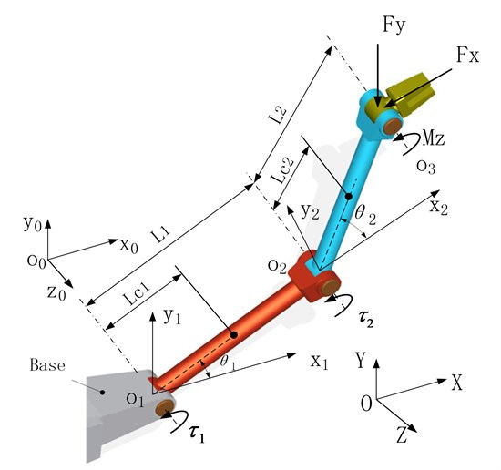
A typical 2R manipulator consists of a base and two links, as shown in Figure 1. The base is fixed on the space station. Joints and are rotating hinge joints, so that links 1 and 2 can revolve around the two joint axes respectively if driven. The global coordinate system is set as . A local coordinate system of is defined along the rotation direction of joint , and the coordinate axis is collinear with the rotating direction of , which is parallel to the global coordinate. The local coordinate system of is defined along the rotating direction of joint and attaches to the base. Another local coordinate system of is defined along the rotation axis of joint and attaches to the link 1.
In operating cases, possible external forces or torques could apply on the ender of manipulator, which can be decomposed along the global coordinate axes such as in -direction, in -direction and around the -direction, as shown in Fig. 1. These external forces on the ender will be balanced by the joint driving torques and of joints and . Besides, the base motion due to the space station movement will be regarded as external excitation motions acting on the manipulator through joint .
Fig. 1Mechanical model of a 2R planar manipulator
2.1. Kinematics
According to the mechanical model of the 2R planar manipulator shown in Fig. 1, the kinematics equations are presented as follows. The transfer matrix of the manipulator can be written as:
where , , , . , are the lengths of link 1 and 2. The position of the manipulator ender is also given by:
The Jacobian matrix of the manipulator is deduced as follows:
From Eqs. (2) and (3), the acceleration of the ender can be deduced as follows:
where is the derivative of Jacobian matrix with respect to time, which is expressed as:
where , .
2.2. Base motion excitation of manipulator
The movement of the spacecraft is regarded as base motion excitation for the 2R manipulator, which can be linear translation or rotation. When the spacecarft is still or moves in straight line with constant velocity, there is no additional force acting on the manipulator. But when it moves in a constant acceleration, the base motion excitation is significant for the manipulator. It is assumed that the base motion acceleration is as follows:
On the other way, if the base movement is a rotating one around the axis, an additional moment will act on the joint which is similar to a friction moment.
2.3. Impact loads of manipulator
The external impact forces determining the dynamic responses of the manipulator include the locking force of joint and the capturing of free-flying target discussed here. Taking the example of capturing of a free-flying target by the manipulator, the impact force and impact moment will act on the ender, they are:
where , which are force components in and -directions, and is the capturing time.
When the free-flying target is captured successfully, it can be regarded as one part of link 2, thus the dynamic characteristics of the manipulator will be changed due to the added mass of the target body.
2.4. Dynamics of the manipulator
Assuming the velocity and acceleration of the mass center of the link , , are and respectively, the angular velocity and the angular acceleration of link around are and respectively. Involving the acceleration of the base movement as shown above, the dynamic equations of the two links without any friction moments are as follows:
Link 1:
Link 2:
where and are the force and the moment acting on the link 1 coming from the base, and and are the force and the moment acting on the link 2 transferred from link 1. and are the external force and the moment acting on the end of link 2, is the distance vector from to . is the inertia moment of the link relative to . is the mass of the link .
Based on Eqs. (9)-(12), the dynamic equations of the 2R manipulator are established as follows:
where is the joint variable, is the inertial matrix, is the damping matrix containing Coriolis force, are the base acceleration and external load and are the driven torques of the two joints. The detailed expressions of the above matrices are given as follows:
.
2.5. Flexibility and friction of joints
The flexibility of each joint affects the dynamic behaviors of the manipulator greatly [11]. Nahvi [12] presented that the joint flexibility has significant effect on the manipulators and causes high frequency vibration. Korayem [13] reported that the increasing of the joint flexibility can decrease the maximum carrying capacity of a manipulator.
Besides the effect of joint flexibility on dynamics of manipulator, the joint friction is another important factor for manipulator dynamics. Nowadays many models have been proposed to describe joint friction. Reyes [14] gave a viscous-Coulomb friction model and used it in tracking control of a 2R planar manipulator. Moreno [15] used an observer of Dahl-viscous friction model in controlling a 2R manipulator, and found that the compensation of this kind of friction model was better than that of viscous-Coulomb friction. Then he proposed a new resolved acceleration controller based on the friction model in trajectory tracking and compared with those of viscous friction and Coulomb friction [16]. Zhang [17] proposed a self-adaptive nonlinear dynamic friction compensation method to carry out friction disturbance compensation in a 2R manipulator. Bona [18] used the static part of the LuGre friction model to predict the friction torque in trajectory tracking control.
In this paper a Stribeck friction model [19] is used to describe the joint friction of the 2R manipulator in zero-gravity state. It is suitable to approximate experiment based values and can avoid the singularity of numerical simulation such as the case of zero angular velocity. It is defined as:
where is a viscous friction coefficient, and are the Coulomb friction coefficient and Stribeck friction coefficient, respectively. and are the coefficients which will determine the curve’s slope of the Coulomb friction and Stribeck friction separately.
Involving the joint stiffness and the friction moment of manipulator as discussed above, Eq. (13) can be re-written as follows:
where is the friction vector, is the joint stiffness matrice, is the angle deviated from the locked position. and are defined as and .
3. Numerical results
3.1. Model parameters
The structural parameters of the 2R planar manipulator shown in Fig. 1 are listed in Table 1.
Assume the friction coefficients of the two joints as introduced in Eq. (14) are 1.5 kgm2/s, 0.2 kgm2/s2, 0.2 kgm2/s2, 1, 1.
Assume the stiffness coefficients of the two joints are 250 N/rad, 50 N/rad. The mass of the capturing target is 1 kg.
Table 1Structural parameter values of the 2R manipulator
Link | (kgm2) | (kg) | (m) | (m) |
1 | 0.04 | 2 | 0.075 | 0.15 |
2 | 0.04 | 2 | 0.075 | 0.15 |
3.2. Simulation method
The 2R manipulator operating in zero-gravity state shown in Fig. 1 is fixed on the base. Because the whole mass of the manipulator is much smaller than that of the attached spacecraft, the movement of manipulator is regarded that it does not affect the dynamics of space station at all.
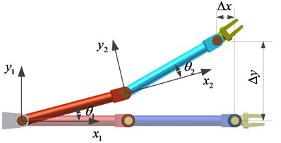
It is supposed the manipulator is locked at the position initially, which is also the zero-position. The moving displacements in Cartesian coordinate system of each link caused by base motion or impact applied on its ender can be defined as shown in Fig. 2. Numerical simulations will be used to compare these displacement components when different impacts and base movement excitations are applied on the manipulator.
Fig. 2Displacements of the ender
3.3. Simulation cases
In order to describe influence of the external impact at ender on the dynamics behavior of the manipulator, three impact cases are chosen and defined as follows:
Impact 1: At initial time 0, and , the manipulator is locked suddenly.
Impact 2: An impact force acts on the ender when capturing a target, and lasts 0.2 s, and then the target slides off.
Impact 3: An impact force acts on the ender when capturing a target, and lasts 0.2 s, and then the target is captured.
There are also 5 cases of base motion excitations, including movements of constant velocity, constant acceleration, periodic ones and so on. The simulation cases including 5 kinds of base excitations with 3 different impacts respectively are listed in Table 2.
Table 2Simulation cases list
Excitation 1 | The base moves in straight path at a constant velocity of , . | Impact 1 |
Impact 2 | ||
Impact 3 | ||
Excitation 2 | The base moves at a constant acceleration of , . | Impact 1 |
Impact 2 | ||
Impact 3 | ||
Excitation 3 | The base moves in a path of periodic oscillation around axis , and , . | Impact 1 |
Impact 2 | ||
Impact 3 | ||
Excitation 4 | Excitation 3 superimposing a narrow- band disturbance. | Impact 1 |
Impact 2 | ||
Impact 3 | ||
Excitation 5 | Excitation 3 superimposing a broad-band disturbance. | Impact 1 |
Impact 2 | ||
Impact 3 |
3.4. Simulated results
The numerical simulation results of each case listed in Table 2 are described as follows.
3.4.1. Excitation 1
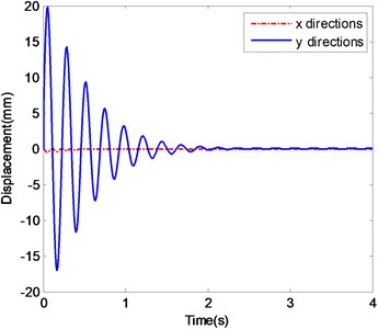
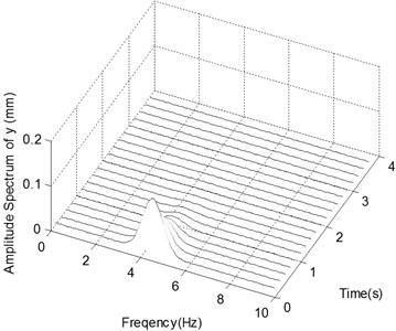
The case of Excitation 1 refers to one in which the base moves in straight path at a constant velocity of , . The ender displacements and the corresponding frequency spectra in - and -directions in the case of Excitation 1 are shown in Fig. 3.
Fig. 3The ender displacements and corresponding spectrograms in y-direction with Excitation 1
a) The displacements of ender with Impact 1
b) The spectrogram of the displacement in -direction with Impact 1
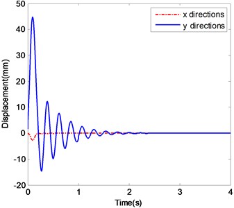
c) The displacements of ender with Impact 2
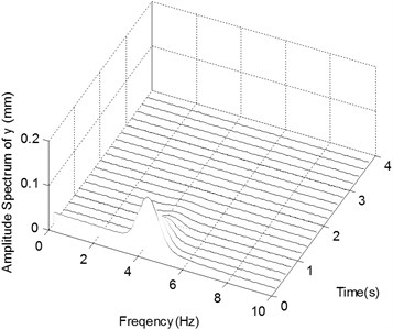
d) The spectrogram of the displacement in -direction with Impact 2
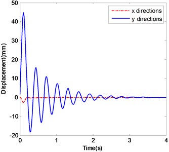
e) The displacements of ender with Impact 3
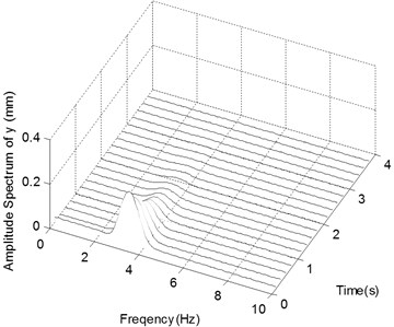
f) The spectrogram of the displacement in
Fig. 3a is the displacement history of the ender where the manipulator is only excited by Impact 1. Because of the impact due to sudden locking of joints, the ender will oscillate and deviate from the desired position. The displacement amplitudes in - and -directions decrease quickly due to the damping of the joint frictions. After about 2.5 s the ender stops fluctuating and stabilizes at 0 in both - and -directions. Fig. 3b is the frequency spectra of the displacement in -direction under Impact 1. The frequency components are centered around 4.3 Hz. The peak values of them decrease over time and become 0 finally.
Fig. 4The ender displacements and corresponding spectrograms in y-direction with Excitation 2
a) The displacements of ender with Impact 1
b) The spectrogram of the displacement in -direction with Impact 1
c) The displacements of ender with Impact 2
d) The spectrogram of the displacement in -direction with Impact 2
e) The displacements of ender with Impact 3
f) The spectrogram of the displacement in
Fig. 3c are the displacements of the ender under Impact 2. Because of the impact effort of capturing a flying target, the ender will deviate sharply from its original position. The displacements in - and -directions fluctuate greatly and their amplitudes decrease quickly. After about 3.5 s, the ender comes to stabilize at 0 in both directions. Fig. 3d is the frequency spectra of the displacement in y-direction under Impact 2. The frequency components are centered around 4.3 Hz too.
Fig. 3e shows the time histories of the ender displacements under the case of Impact 3. It shows similar behaviors of those of the above case of Impact 2, but the stabilizing time is about 5 s. Fig. 3f is the frequency spectra of the ender and the frequency components are centered around 3.3 Hz.
3.4.2. Excitation 2
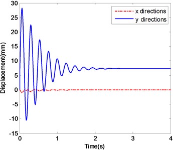
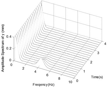
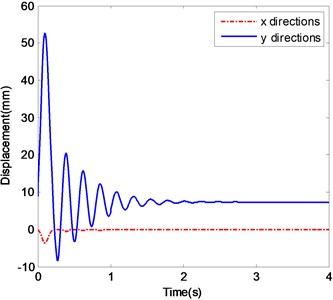
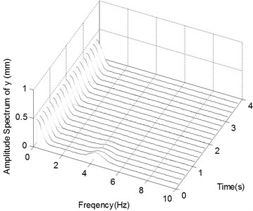
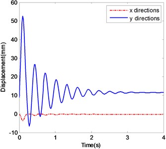
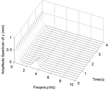
The case of Excitation 2 refers to one that the base moves at a constant acceleration of , . In this case the simulated ender displacements and the corresponding frequency spectra in -direction are shown in Fig. 4.
Fig. 4a and b show the displacement histories and corresponding frequency spectra of the ender movements under the condition of Excitation 2 together with Impact 1. The stabilizing processes and central values of frequency components of the ender displacements are different, i. e. 7.5 mm in -direction and about 0 mm at -direction at the time of 3 s. The frequency components are centered around 0 Hz and 4.3 Hz in the frequency spectra of displacement in -direction.
Fig. 4c and d show those data of the ender movements in the case of Excitation 2 with Impact 2. The time histories and frequency spectra of the ender displacements are similar to those of the case of Impact 1, only except that the low frequency components appear at the beginning time due to the impact which acts on the ender.
Fig. 4e shows the displacement histories in the case of Excitation 2 with Impact 3, which are similar with the above case of Impact 2, but the stabilizing time is about 4s, and the stabilizing displacement in -direction is 11.5 mm. In Fig. 4f the two large frequency components of displacement in -direction are centered on 0 Hz and 3.3 Hz.
3.4.3. Excitation 3
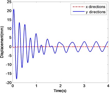
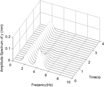
The case of Excitation 3 refers to one that the base moves in a path of periodic oscillation around the coordinate axis of the global system and . In this case the simulated ender displacements and the corresponding frequency spectra in -direction are shown in Fig. 5.
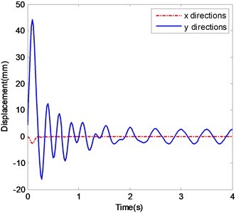
Fig. 5a and b show the displacement histories and corresponding frequency spectra of the ender movement under the condition of Excitation 3 together with Impact 1. After a short fluctuating the displacements of the ender tend to be in a periodic pattern, and period of which is equal to that of the external excitation. The stable amplitudes are about 0.02 mm in -direction and 2.5 mm in -direction after 2.5 s. The frequency components in -direction are centered around 2 Hz and 4.3 Hz, and the component of 2 Hz does not decrease over time.
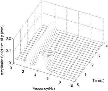
Fig. 5c and d show those data of the ender movement in the case of Excitation 3 but with Impact 2. They are similar to the case of Impact 1, except appearing obviously a low frequency component at the beginning of impact.
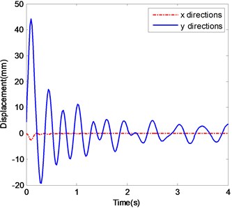
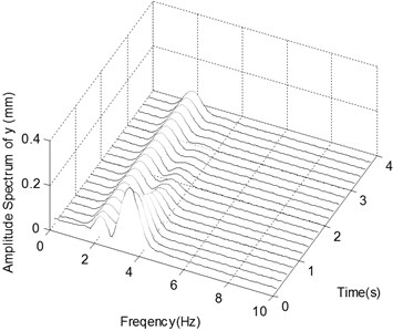
Fig. 5e and f show the same behavior as Fig. 5c and d. But after 4 s the amplitude in -direction is about 3 mm. The two main frequency components are centered on 2 Hz and 3.3 Hz.
Unlike the cases of Excitation 1 and Excitation 2, the displacements under Excitation 3 tend to periodic motions finally. The frequency components centered on 2 Hz are caused by the periodic base excitation and do not decrease over time.
3.4.4. Excitation 4
The case of Excitation 4 refers to one that Excitation 3 is superimposed by a narrow-band noise. In this case the simulated ender displacements and the corresponding frequency spectra in -direction are shown in Fig. 6.
Fig. 6 shows the power spectrum density (PSD) and time history of the narrow-band noise added as disturbance with frequency components centered around 2 Hz.
Fig. 5The ender displacements and corresponding spectrograms in y-direction with Excitation 3
a) The displacements of ender with Impact 1
b) The spectrogram of the displacement in -direction with Impact 1
c) The displacements of ender with Impact 2
d) The spectrogram of the displacement in -direction with Impact 2
e) The displacements of ender with Impact 3
f) The spectrogram of the displacement in -direction with Impact 3
Fig. 6Narrow-band disturbance
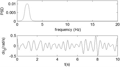
Fig. 7The ender displacements and corresponding spectrograms in y-direction with excitation 4
a) The displacements of ender with Impact 1
b) The spectrogram of the displacement in -direction with Impact 1
c) The displacements of ender with Impact 2
d) The spectrogram of the displacement in -direction with Impact 2
e) The displacements of ender with Impact 3
f) The spectrogram of the displacement in
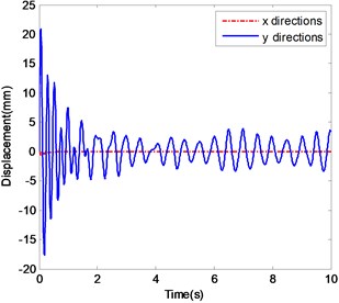
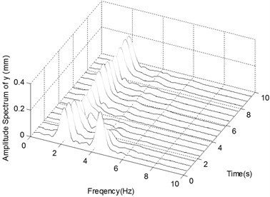
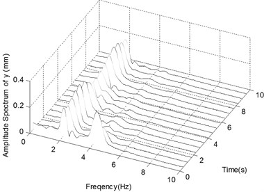
Fig. 7a and b show the displacement history and corresponding frequency spectra of the ender movement under the condition of Excitation 4 together with Impact 1. After a transient process of about 2.5 s the ender displacements tend to oscillate in the range from -5 mm to 5 mm but not to be periodic. The peaks in frequency spectra are centered on 2 Hz and 4.3 Hz, together with small and continuous frequency contents distributing from 0 Hz to 6 Hz.
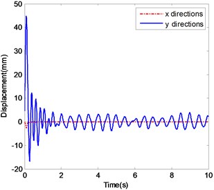
Fig. 7c and d show the ender movements in the case of Excitation 4 with Impact 2. After a shorter transient process of about 1.5 s the displacements tend to oscillate in the range from -5 mm to 5 mm too. The dynamic behavior of this case is much similar as Impact 1.
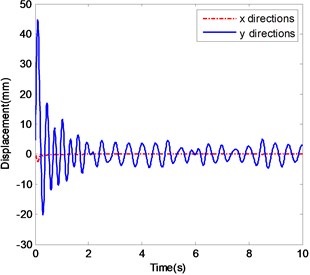
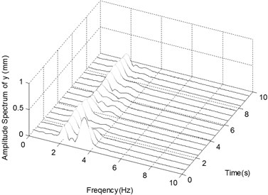
Fig. 7e and f show the ender movements in the case of Excitation 4 with Impact 3. After about 2 s the displacements tend to vary in the same range. The two frequency content peaks are centered around 2 Hz and 3.3 Hz.
Compared with Excitation 3, many noise frequency components from 0 Hz to 6 Hz appear in the frequency spectra under Excitation 4.
3.4.5. Excitation 5
The case of Excitation 5 refers to one when Excitation 3 is superimposed by a broad-band noise, which is shown in Fig. 8.
Fig. 8Broad-band disturbance
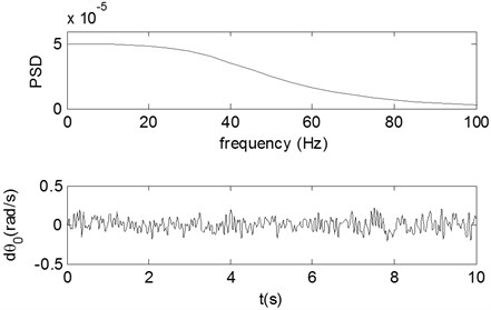
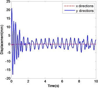
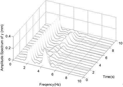
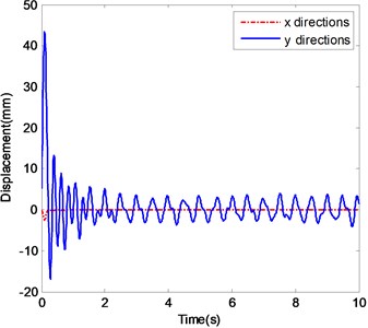
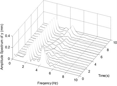
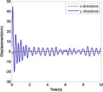
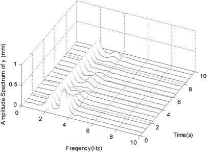
In this case, the simulated ender displacements and the corresponding frequency spectrum diagrams in y-direction are shown in Fig. 9. Fig. 9a and b show the displacement histories and corresponding frequency spectra of the ender movement under the condition of Excitation 5 together with Impact 1. The pattern of the ender movements is the same as in Excitation 4, but only the noise frequencies are different as their distribution range is 0~10 Hz. The similar simulated results are also illustrated in Fig. 9c and d of the case of Excitation 5 with Impact 2, and Fig. 9e and f of the case of Excitation 5 with Impact 3.
3.5. Discussions
As shown by the simulated ender displacements, the impacts and base excitations have great influence on the dynamic behaviors of the manipulator. When the base is static or moves in a straight line with constant velocity, the displacements of the ender will be easily stabilized at zero finally. If the base moves in constant acceleration, the displacements of the ender will be gradually stabilized at a certain offset position.
From Fig. 3 it can be seen that under Excitation 1, when the external impacts act on the manipulator, the ender deviates from its desired position and fluctuates to stabilize at zero-position finally. Due to the successful capturing of a flying target, the frequency spectrum components of the case of Impact 3 are little different from those of Impact 1 and Impact 2. From Fig. 4 the simulated results of ender motions in case of Excitation 2 show to have similar dynamic behaviors as those of Excitation 1, but different from stabilizing displacements, and the frequency components centered around 0 Hz appear due to the accelerating motions of the base.
Fig. 9The ender displacements and corresponding spectrograms in y-direction with excitation 5
a) The displacements of ender with Impact 1
b) The spectrogram of the displacement in -direction with Impact 1
c) The displacements of ender with Impact 2
d) The spectrogram of the displacement in -direction with Impact 2
e) The displacements of ender with Impact 3
f) The spectrogram of the displacement in -direction with Impact 3
When the base motion excitation is periodic, the ender displacements become stable at last. From Fig. 5 the captured flying target can change not only the frequency components of ender motions, but also the amplitudes of the stable and periodic motions. The narrow-band and broad-band disturbances of the base motions will affect the vibrations of the ender certainly. Comparing with the narrow-band noise, the broad-band disturbance is much more obvious in both time domain and spectra. Capturing flying target can also change the dynamic behaviors of the manipulator greatly, because the nature frequencies of the system composed of manipulator and target could change greatly.
4. Conclusions
In this paper the kinematics and dynamic governing equations of a 2R manipulator subjected to external impacts and base motion excitations are established, supposing the mass parameters of the manipulator and flying target are far less than of the attached spacecraft. And then the dynamic behaviors of the space 2R manipulator in zero-gravity state under different impacts and base motion excitations are simulated and compared.
According to the numerical simulated results, the manipulator will greatly oscillate when it is suddenly locked or impacted at the ender, and the displacement amplitudes of the ender decrease gradually because of joint friction, when the base is static or moves in constant acceleration. The ender will gradually stabilize in different ways if the impact loads are different. If the base moves in a periodic path, the external excitations also affect the ender displacements, even the periodic motions are not changed. The superimposed broad-band or narrow-band disturbances of the external excitations will also disturb the ender motions.
There are obvious low frequencies caused by the flying target impact in frequency spectra compared with those due to impact force acting on the ender. The captured flying target can change the dynamic behaviors of the manipulator greatly due to the changing of the nature frequencies of the whole system.
References
-
Ali S., Moosavian A., Papadopoulos E. Free-flying robots in space: an overview of dynamics modeling, planning and control. Robotica, Vol. 25, Issue 5, 2007, p. 537-547.
-
Mukherjee R., Chen D. Control of free-flying under actuated space manipulators to equilibrium manifolds. IEEE Transactions on Robotics and Automation, Vol. 9, Issue 5, 1993, p. 561-570.
-
Nokleby S. B. Singularity analysis of the Canadarm2. Mechanism and Machine Theory, Vol. 42, Issue 4, 2007, p. 442-454.
-
Kim J., Marani G., Chung W. K., Yuh J. A general singularity avoidance framework for robot manipulators: task reconstruction method. IEEE International Conference on Robotics and Automation, Vol. 5, 2004, p. 4809-4814.
-
Phuoc L. M., Martinet P., Lee S., Kim H. Damped least square based genetic algorithm with Gaussian distribution of damping factor for singularity-robust inverse kinematics. Journal of Mechanical Science and Technology, Vol. 22, Issue 7, 2008, p. 1330-1338.
-
Agrawal S. K., Chen M. Y., Annapragada M. Modeling and simulation of assembly in a free-floating work environment by a free-floating robot. Transactions of the ASME, Journal of Mechanical Design, Vol. 118, Issue 1, 1996, p. 115-120.
-
Dubowsky S., Durfee W., Corrigan T. A laboratory test bed for space robotics: the VES-II. IEEE International Conference on Intelligent Robots and Systems, Vol. 3, 1995, p. 1562-1569.
-
Yoshida K. Experimental study on the dynamics and control of a space robot with experimental free-floating robot satellite (EFFORTS) simulators. Advanced Robotics, Vol. 9, Issue 6, 1995, p. 583-602.
-
Nohmi M. Attitude control of a tethered space robot by link motion under microgravity. IEEE International Conference on Control Applications, Vol. 1, 2004, p. 424-429.
-
Bateman V. I. Pyroshock standards. Sound and Vibration, Vol. 45, Issue 3, 2011, p. 5-6.
-
Magnani G. A., Rocco P., Rusconi A. Modeling and position control of a joint prototype of DEXARM. IEEE International Workshop on Advanced Motion Control, 2008, p. 562-567.
-
Nahvi H., Ahmadi H. Dynamic simulation and nonlinear vibrations of flexible robot arms. Pakistan Journal of Applied Sciences, Vol. 3, Issue 7, 2003, p. 510-523.
-
Korayem M. H., Nikoobin A. Maximum payload for flexible joint manipulators in point-to-point task using optimal control approach. The International Journal of Advanced Manufacturing Technology, Vol. 38, Issue 9-10, 2008, p. 1045-1060.
-
Reyes F., Kelly R. Experimental evaluation of model-based controllers on a direct drive robot arm. Mechatronics, Vol. 11, Issue 3, 2001, p. 267-282.
-
Moreno J., Kelly R., Campa R. Manipulator velocity control using friction compensation. IEEE Proceedings on Control Theory and Applications, Vol. 150, Issue 2, 2003, p. 119-126.
-
Moreno J., Kelly R. Pose regulation of robot manipulators with dynamic friction compensation. IEEE Conference on Decision and Control, 2005, p. 4368-4372.
-
Zhang Y., Liu G., Goldenberg A. A. Friction compensation with estimated velocity. IEEE International Conference on Robotics and Automation, Vol. 3, 2002, p. 2650-2655.
-
Bona B., Indri M., Smaldone N. Rapid prototyping of a model-based control with friction compensation for a direct-drive robot. IEEE/ASME Transactions on Mechatronics, Vol. 11, Issue 5, 2006, p. 576-584.
-
Berger E. J. Friction modeling for dynamic system simulation. Applied Mechanics Reviews, Vol. 55, Issue 6, 2002, p. 535-577.
About this article
The authors gratefully acknowledge that the work was supported by the Open Project of State Key Laboratory of Robotics of Chinese Academy of Sciences (Grant No. 2012-O04).
