Abstract
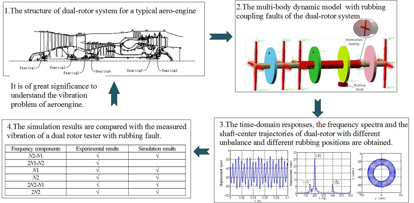
In this paper, a dual-rotor system multi-body dynamic model with rubbing coupling faults is established for practical aero-engine. In the model, the rubbing fault simulation method is introduced, the coupling effect between the internal and external rotor is considered. The numerical simulations of rotor vibration are accomplished by the utilization of multi-body dynamic platform, where the simulation model consists of discs unbalances and local rub-impact between discs and casing shells. The time-domain responses, the frequency spectra and the shaft-center trajectories of dual-rotor with different unbalance and different rubbing positions are obtained. The vibration and its transmission characteristics of the inner and outer rotors are calculated. Finally, the simulation results are compared with the measured vibration of a dual rotor tester with rubbing fault. The simulation results are consistent with the measured results, which confirms the feasibility of the established model and the multi-body dynamics simulation method in this paper. The application of multi-body dynamics simulation method in aero-engine can deepen the understanding of the internal operation nature and laws of aero-engine, reduce the repetition of physical tests, greatly improve the efficiency and quality of development, accelerate the research and manufacture process.
Highlights
- A multi-body dynamic model of rotor-bearing-rotor coupling system is established for aero-engine, and a rubbing coupling faults simulation method is proposed.
- The influence of rubbing position and unbalance on the vibrations of dual-rotor with rubbing fault is analyzed, and the vibration and its transmission characteristics of dual-rotor are calculated.
- The simulation results are compared with the measured vibration of a dual rotor tester with rubbing fault.
1. Introduction
When it comes to aero-engine rotor system, rotor rubbing fault becomes one of the most common faults [1]. It not only brings about increase of the rotor stator gap, wearing, cracking or even breaking of a blade bearing, but may result in motion of rotor system instability, deformation of casing shells caused by vibration, which will seriously affect the efficiency of engine once exceeding the standard [2, 3]. Hence, the research on the influence of dual-rotor system rotor-stator rubbing fault to system response characteristics occupies an important role in the diagnosis and identification of aero-engine rubbing fault.
In recent years, the research on the dynamic characteristics of the dual-rotor system with rub-impact fault has been conducted by relevant scholars. Qingkai Han [4] built a rigid-flexible multi-body model of the dual-rotor system with local rub-impacts with MSC. Adams, based on rigid-flexible multi-body simulations, investigated the nonlinear dynamical characteristic. Guihuo Luo [5] established a nonlinear dynamic model of dual-rotor system with high-dimensional rubbing fault, and analyzed the dynamic response characteristics of counter-rotating dual-rotor system. The results show that the friction fault will make the axis orbit of the system become messy and except the two unbalance excitation frequency, the combination frequency also appeared in frequency Spectrum. Huiqun Yuan [6] established a multi-disc double rotor-stator coupling system dynamic model, taking the coupling of low-pressure rotor and high-pressure rotor through the intermediate bearing into consideration together with high-pressure rotor and casing shells, in which the fourth-order partial differential equations of motion of the continuum double rotor multi-disc-stator system were formed. Besides, he also concentrated on analyzing the effect of speed and intermediate bearing’s stiffness to the rub response, the results show that appropriate settings of intermediate bearing stiffness can reduce the amplitude of rub-impact fault. Junhong Zhang et al. [7] had implemented tests on misalignment and single-point rub-impact fault based on the experimental platform of aero-engine rotor with casing shells, the results show that the rubbing fault causes a large number of doubling and combination frequency. Yang Yang etc. [8] established a dual-rotor system capable of describing the mechanical vibration resulting from two imbalances and fixed point rubbing, studied the dynamic characteristics of dual-rotor system with fixed point rubbing by the means of theoretical analysis and experimental. The results indicate that for the case of fixed point rubbing, several combination frequencies in the responses of the dual-rotor system are identified as the particular fault frequencies. Chen G. [9] established a new rotor-ball bearings-support-stator coupling system dynamic model and studied the rubbing coupling faults used the method of combining theory with experiment. Hui Ma, etc. [10] summarized the research results of rub-impact faults home and abroad and analyzed the typical fault characteristics for three kinds of rub-impact forms, such as single-point rubbing, local rubbing and circular rubbing.
Aero - engine structure is complex, working state is changeable, and it is difficult to directly reproduce vibration fault on the prototype machine. Multi-body dynamic analysis technology based on virtual prototyping has been widely used in the research of rotor dynamics. ADAMS is based on the theory of multi-body system dynamics and contains many professional modules. It can be used to establish complex kinematics and dynamics models of mechanical system and the simulation of system motion and dynamic characteristics under actual working conditions can be realized. Based on the theories of dynamics of dual-rotor system, together with the rub-impact mechanism involving its stiffness and damping and friction, a multi-body dynamic model of the aero-engine dual-rotor system is built on the software platform of ADAMS. Based on the multi-body dynamic model, the unbalance and rub-impact faults of dual-rotor are simulated, and the vibration transmission law of unbalance and rub-impact caused by vibration coupling is revealed through the analysis of the results. It provides a verification method for the theoretical research of aero-engine rotor with rubbing faults.
2. Establishment of the dynamic model for dual-rotor system
2.1. A simplified model of dual-rotor system
Fig. 1 is a typical aero-engine dual-rotor system structure, the low-pressure rotor consists of four fans and one turbine, supported by bearings of 1, 2, 3 and 6. The high- pressure rotor is composed of nine compressor discs and a high-pressure turbine, which is supported by bearings of 3 and 5.
Fig. 1The supporting structure of dual-rotor system

According to the principle of dynamic similarity, the dual-rotor system of figure 1 is simplified. The rotating shaft is simplified as beam element. The discs and blades of the compressor and the turbine are considered as rigid bodies with rotating effect, which are simplified as discs in the form of concentrated mass and moment of inertia in their centroid position. In order to facilitate calculation, the coupling in the prototype machine is simplified as a rotating shaft and the supports are simplified as isotropic linear elastic supports. The specific simplification methods are as follows.
The four-stage fans in the low-pressure rotor is simplified as the disc 1 (referred to as LPC), the low-pressure turbine disc is equivalent to disc 2 (referred to as LPT). Nine compressor discs of high-pressure rotor are simplified as disc 3 (referred to as HPC), high-pressure turbine disc equivalent to disc 4 (referred to as HPT). The spring stiffness is the equivalent stiffness of bearing 1, squirrel cage, bearing cone and auxiliary plate. The stiffness is the combination stiffness of bearings 2 and 3. The stiffness of bearings 4, 5 and 6 are equivalent to , and respectively. The dynamic model of Fig. 2 is obtained through simplification,
Fig. 2The structure schematic diagram of dual-rotor system

2.2. Equations of motions
The system analytic model is established by using the Lagrange equation as follows:
where, and are generalized coordinates and generalized velocities respectively. and are the kinetic energy and potential energy of the system respectively. is the energy dissipation function of the system. is the generalized external excitation force. If the work done by some exciting force has been expressed as the kinetic energy and potential energy form of the vibration system, or the form of energy dissipation function, then these exciting forces are no longer considered on the right side of the equation. In this rotor system, the influence of energy dissipation function is neglected. Function Eq. (1) can be written as:
Considering the motion equation of the rotor, and ignoring the external excitation. The differential equations of the system motion are derived and arranged as follows:
3. Establishment and verification of multi-body dynamic model for dual-rotor system with rubbing faults
3.1. Model verification
The basic parameters of the dual-rotor structure are shown in Table 1. is the diameter of the low-pressure shaft, while and are respective illustration of the inner and outer diameter of high-pressure shaft. In order to facilitate the calculation, the four discs use the same size, and are the diameter and thickness of the discs respectively.
Table 1The basic parameters of dual rotor system
Parameters | Values | Parameters | Values |
185 mm | 1500 mm | ||
330 mm | 200 mm | ||
500 mm | 30 mm | ||
685 mm | 65 mm | ||
1015 mm | 80 mm | ||
1200 mm | 90 mm | ||
1315 mm | – | – |
Table 2Mode comparison
Based on finite element | Based on ADAMS |
 1st 118.2 Hz |  1st 124.3 Hz |
 2st 171.7 Hz |  2st 167.8 Hz |
In order to verify the correctness of the model, the first two order natural frequencies of dual-rotor based on ADAMS are compared with the results based on the finite element method.
The results show that the first two order modes are the same, and the frequency difference is less, which can verify the rationality of the model.
3.2. The multi-body dynamic model of rub-impact
The ‘Impact’ is used to calculate the rub-impact force in ADAMS, which is based on the impact function to calculate the contact force between the two objects. The contact force is composed of two parts, the first part is the elastic force due to the mutual penetration between the two objects, the other part is the damping force produced by relative speed.
Rub-impact mechanics expression:
Among them, is the stiffness coefficient of rub-impact, and are the initial clearance and actual distance between the two contact objects in the rubbing process. is the maximum damping coefficient which used to characterize the collision energy loss. is the rotating shaft speed (inner and outer pressure rotor speed are and respectively). is rub-impact index which used to represent the nonlinear degree of material. is the penetration depth.
The multi-body dynamic model of dual-rotor rub-impact based on ADAMS is illustrated in Fig. 3. In the model, the elastic supportings are use the “spring” in the horizontal and vertical direction to simulate and the parameter setting of stiffness like the following Table 3. The dual-rotor unbalance is simulated by adding a mass block on the low-pressure compressor disc and the high-pressure compressor disc. A rubbing block is arranged at a certain distance from the low-pressure disc and the different rubbing conditions are simulated the material parameters are set according to steel. The dynamic friction between the turbine disc and the rubbing block is 0.1.
Fig. 3The dual-rotor system model based on Adams
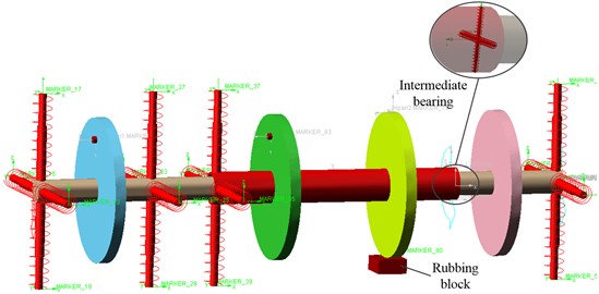
Table 3Parameter setting of the simulation model base on ADAMS
Parameter | Data | Parameter | Data |
Rub-impact stiffness | 1e6 N/m | Low-rotor motion | 8800 r/min |
Rub-impact damping | 100 Ns/m | High-rotor motion | 12000 r/min |
Force exponent | 1.5 | 1e7 N/m | |
Penetration depth | 0.1 mm | 5e7 N/m | |
Rubbing clearance | 0.1 mm | 1e7 N/m | |
LPC unbalance quality | 24.5 g | 1e8 N/m | |
HPC unbalance quality | 20 g | 1e7 N/m |
The software ADAMS provides a variety of integrators, this paper selects the GSTIFF integrator with high speed and high solve precision. There are three kinds of GSTIFF integrator integral format: I3, SI2 and SI1, the speed of solving I3 format is faster, but error will be generated when it comes to speed, especially the acceleration, the SI1 format is not suitable for processing contact problems with friction [11], so this paper chooses SI2 integral method, the integral error is set to 0.001.
4. Simulation results of dual-rotor system
As what is shown in Table 4, the vibration characteristics of the dual-rotor system under different operating conditions are analyzed. In this paper, time-domain responses, frequency spectra and shaft-center trajectories of the high and low pressure discs are obtained via simulation analysis under four kinds of working conditions.
Table 4Four kinds of working conditions
Parameter | Condition Ⅰ | Condition Ⅱ | Condition Ⅲ | Condition Ⅳ |
√ | √ | √ | √ | |
√ | – | – | √ | |
LPT-Rubbing | – | √ | – | – |
HPT-Rubbing | – | – | √ | √ |
4.1. Unbalance response of dual-rotor system
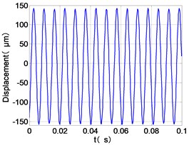
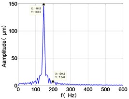
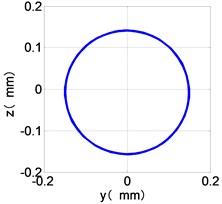
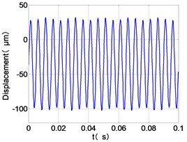
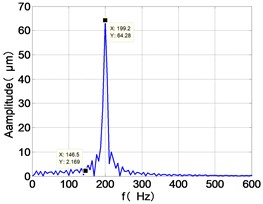
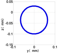
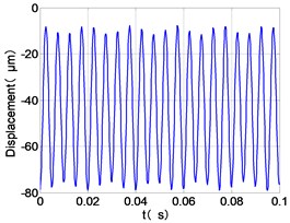
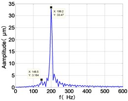
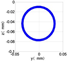
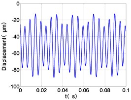
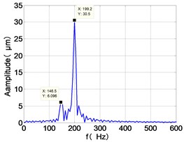
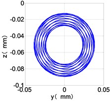
The vibration of the dual-rotor unbalance is simulated by applying me1 on low pressure compressor disc and on high pressure compressor disc under working condition Ⅰ. The time-domain responses, frequency spectra and shaft-center trajectories of the high and low pressure discs are obtained as shown in Fig. 4.
From the Fig. 4, we can find that the vibration of the dual-rotor unbalance is in a certain vibration state. The four discs are in a certain range of periodic reciprocating vibration. The main frequencies of unbalanced response are and . The time domain diagram and axis trajectory of the low and high pressure turbine discs are under zero bits by gravity.
The time domain diagram of low and high pressure compressor discs are regular, and occupies the absolute priority in the frequency domain respectively without other frequency components, and the amplitude of for the high-pressure compressor disc reaches approximately half of the for low-pressure compressor disc. The trajectory line of the discs are in round shape. There are multiple peaks in time domain of the low and high turbine disc. and existing in the frequency domain and enjoys the absolute advantage. The shape of the discs trajectory appears some confusion within a certain range and the low pressure turbine disc more obvious than high pressure turbine disc.
From the Table 5, we can find that the amplitude of frequencies and for four discs decreases step by step along the transmission paths LPC-LPT-HPT-HPC and HPC-HPT-LPT-LPC respectively.
Table 5Vibration amplitude of four discs
Parameter | LPC | HPC | HPT | LPT | ||||
Value (μm) | ||||||||
148.5 | 7.344 | 2.169 | 64.28 | 3.164 | 33.47 | 6.096 | 30.5 | |
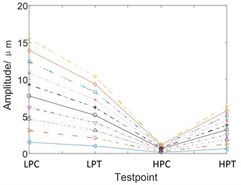
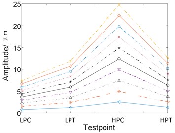
With the help of analytical method, the vibration of the four discs is measured during the unbalance of the LPC from 200 g.mm to 2000 g.mm. From Fig. 5(a) we can find that the amplitude of is in the order of LPC > LPT > HPT > HPC. The amplitude variation diagram of frequency of the four discs during the change of HPC unbalance from 200 g.mm to 2000 g.mm is obtained, as shown in Fig. 5(b). As can be seen from Fig. 5(b), the amplitude of is in the order of HPC-HPT-LPT-LPC. Transmission law of unbalanced vibration of dual-rotor based on analytical method is consistent with the simulation results based on multibody dynamics.
Fig. 4Case Ⅰ, the vibration characteristic of the dual-rotor system
a) LPC time-domain
b) LPC frequency spectra
c) LPC shaft-center trajectories
d) HPC time-domain
e) HPC frequency spectra
f) HPC shaft-center trajectories
g) HPT time-domain
h) HPT frequency spectra
i) HPT shaft-center trajectories
j) LPT time-domain
k) LPT frequency spectra
l) LPT shaft-center trajectories
Fig. 5Variation curves of fundamental frequency of four discs vibration with unbalance
a)
b)
4.2. LPT-rubbing
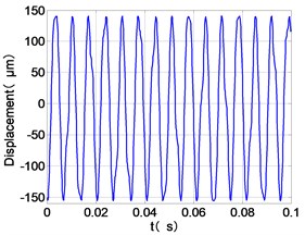
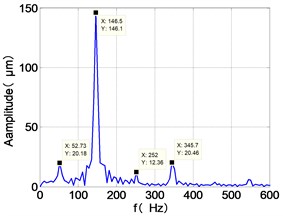
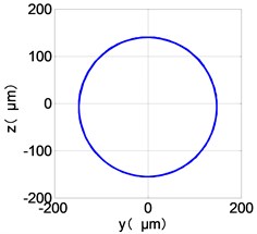
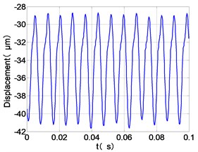
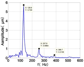
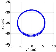
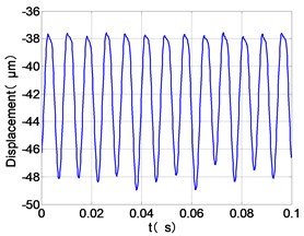
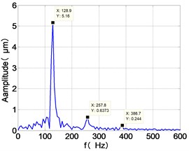
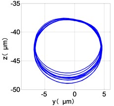
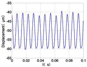
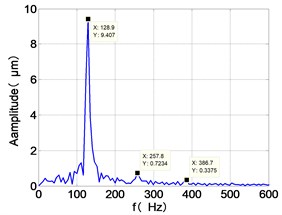
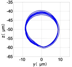
The vibration response characteristics of dual-rotor with low-pressure turbine disc rubbing faults are simulated under the low-pressure compressor disc unbalance by using the operating condition Ⅱ. The time-domain responses, frequency spectra and shaft-center trajectories of the high and low pressure discs are obtained as shown in Fig. 6.
Fig. 6Case Ⅱ, the vibration characteristic of the dual-rotor system
a) LPC time-domain
b) LPC frequency spectra
c) LPC shaft-center trajectories
d) HPC time-domain
e) HPC frequency spectra
f) HPC shaft-center trajectories
g) HPT time-domain
h) HPT frequency spectra
i) HPT shaft-center trajectories
j) LPT time-domain
k) LPT frequency spectra
l) LPT shaft-center trajectories
It can be seen from the figure that the frequency spectrum of each disc mainly falls to (2)/2 and there are combination of frequency components such as 2, , The amplitude of the principal frequency of the four discs is LPC > LPT > HPC > HPT.
The center orbit of the high-pressure disc and low-pressure turbine discs rebounds along the rubbing direction. The trajectory lines of the low-pressure compressor disc and the turbine disc are circular, and disorder appears at the top of the trajectory of the low-pressure turbine disc. The trajectory lines of the high-pressure compressor disc and turbine disc are circular and appear disorder at the bottom of the trajectory.
4.3. HPT-rubbing
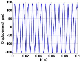
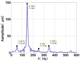
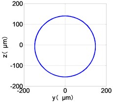
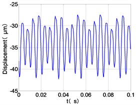
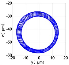
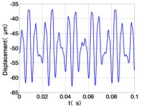
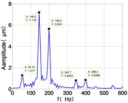
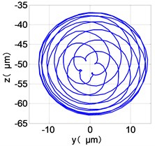
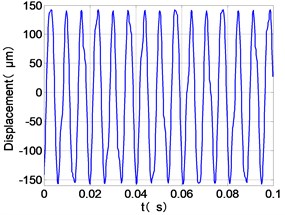
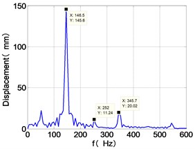
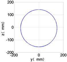
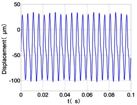
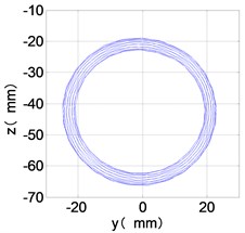
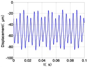
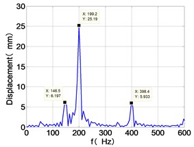
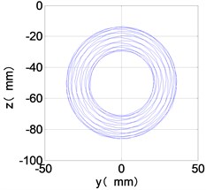
The vibration response of dual-rotor and the transmission of vibration between high and low pressure rotor are analyzed under the situation of rotor unbalance and high-pressure turbine rubbing. Simulating with the case Ⅲ and case Ⅳ in the Table 4. Their vibration features are shown in Fig. 7 and Fig. 8 respectively.
Fig. 7Case Ⅲ, the vibration characteristic of the dual-rotor system
a) LPC time-domain
b) LPC frequency spectra
c) LPC shaft-center trajectories
d) HPC time-domain
e) HPC frequency spectra
f) HPC shaft-center trajectories
g) HPT time-domain
h) HPT frequency spectra
i) HPT shaft-center trajectories
j) LPT time-domain
k) LPT frequency spectra
l) LPT shaft-center trajectories
Fig. 8Case Ⅳ, the vibration characteristic of the dual-rotor system
a) LPC time-domain
b) LPC frequency spectra
c) LPC shaft-center trajectories
d) HPC time-domain
e) HPC frequency spectra
f) HPC shaft-center trajectories
g) HPT time-domain
h) HPT frequency spectra
i) HPT shaft-center trajectories
j) LPT time-domain
k) LPT frequency spectra
l) LPT shaft-center trajectories
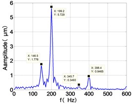
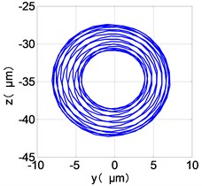
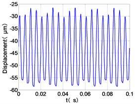
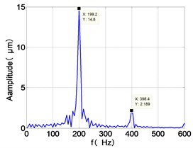
From the Fig. 7, we can find that the time domain diagram of low-pressure compressor disc is regular, the frequency spectrum is mainly dominated by the and the combination frequencies , 1/4 and 2 appeared. The trajectory line of LPC is in round shape. The time domain diagram of the high-pressure compressor disc is under zero bits, the frequency spectrum are dominated by the combination frequencies , , , 2 and the frequency occupies the absolute priority. The trajectory line of HPC appears some confusion within a certain range. The frequency spectrum of the high-pressure turbine disc is dominated by the combination frequencies and 2, the trajectory line appears some confusion within a certain range. The frequency spectrum of the low-pressure turbine disc is mainly dominated by the frequencies and , the combination frequencies , 1/4 and 2 appeared. The trajectory line of LPT appears complex like ‘petal’.
Compared the vibration response with LPT-rubbing, the frequency spectrum of the four discs became more complex with HPT rubbing faults, the combination frequencies , 2, , 2 and 1/4 occupied the priority. The changes of frequency spectrum amplitude of the high-pressure turbine disc is most obvious, has significantly improved. The time-domain changes of low-pressure turbine disc is maximum, appeared many different peaks. The trajectory line of low-pressure turbine disc becomes the most complex like ‘petal’.
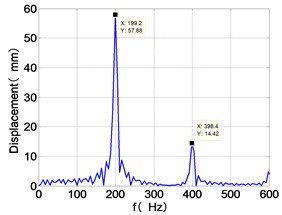
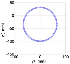
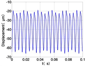
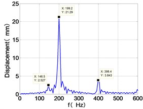
It can be seen from Fig. 8 that the time domain diagram of low-pressure compressor disc is regular, the frequency spectrum is dominated by , together with the combination frequencies , 1/4 and 2, the trajectory line is in round shape. The frequency spectrum of high-pressure compressor disc dominated by , 2 and , the trajectory line appears confusion within a small certain range. The frequency spectrum of the high-pressure turbine disc and low-pressure turbine disc are dominated by , 2 and , in which take the absolute priority. Their trajectory lines appear some confusion within a small certain range and the trajectory lines of low-pressure turbine disc appeared more complex than the high-pressure turbine disc.
Comparison Fig. 8 with Fig. 7, we can draw the conclusion: after adding the unbalance value of high-pressure compressor disc, the frequency spectra of each disc are dominated by and , the combination frequencies 2, 2 and 1/4 appeared. The vibration characteristics of LPC not change. in the frequency spectrum of the high-pressure compressor disc disappears, which is mainly composed of and 2. The amplitude of , and 2 in the frequency spectrum of high-pressure turbine disc are increased. The Low-pressure turbine disc’s frequency spectrum changes is the largest, the main frequency components from and in Fig. 6 into in Fig. 7, and the combination of frequency components reduced on the whole.
5. Verification of simulation results
Wen Bangchun, Jin Yezhuang and others have developed an aero-engine testing machine with similar structure, as shown in Fig. 9. Based on this testing machine, the rubbing fault of rotor is studied.
Fig. 9Structure of aero-engine rub-impact rotor tester: 1 – motor, 2 – coupling, 3 – engine model, 4 – front horizontal support, 5 – eccentric transmission and locking mechanism, 6 – hanging, 7-10 – displacement sensor, 11-12 – acceleration sensor
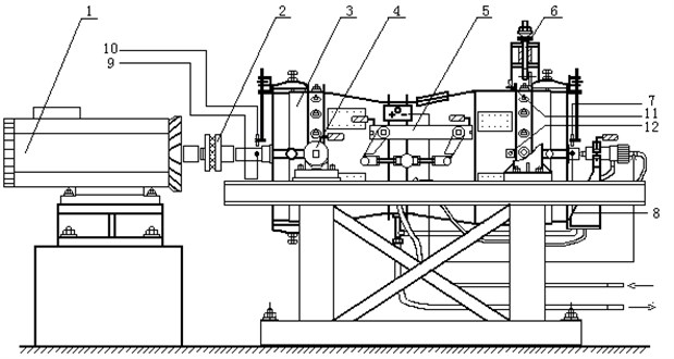
The time domain and frequency spectrum of vibration displacement in the vertical and horizontal directions of the dual-rotor are obtained based on the dual-rotor experiment rig. Through the analysis of the test results of dual-rotor, it can be seen that when rubbing occurs in the rotor system, the frequency spectrum of the vibration signal contains not only the fundamental frequency components of the high and low pressure rotors, but also one or several combination frequencies components. Under the above different rubbing conditions, the test results show that the combination of the components of the signal in the vertical direction is shown in Table 6. It provides a verification method for simulation results.
Table 6The frequency components of experimental and simulation results
Frequency components | Experimental results | Simulation results |
√ | √ | |
2 | √ | – |
√ | √ | |
√ | √ | |
2 | √ | √ |
2 | √ | √ |
The simulation result is also consistent with the measured vibration of an aero-engine happening rub-impact practically, which confirms the feasibility of the established model and simulation method.
6. Conclusions
In the dual-rotor system of the aero-engine, the vibration of the inner and the outer rotor will be transmitted through intermediate bearing. The vibration of the inner rotor and the outer rotor will have coupling effect. The vibration caused by this coupling effect under rotor imbalance and rubbing fault has different transmission laws. The following conclusions are obtained through the simulation in this paper:
1) The unbalance response of the rotor is different due to the location and size of the unbalance. In the unbalance response of the dual rotor system, the unbalance response frequencies and of inner and outer rotors are absolutely dominant, and the axis trajectory is basically regular. The vibration of the dual rotor caused by unbalance of inner rotor and outer rotor decreases step by step on the transmission path LPC-LPT-HPT-HPC and HPC-HPT-LPT-LPC respectively.
2) In the rub-impact response of the dual-rotor system, besides the inner and outer rotor rotation frequencies, the combined frequency of the inner and outer rotor rotation frequencies also appears. Due to the coupling effect of the intermediate bearings, the response of the system becomes complicated and is no longer the sum of the responses caused by simple unbalanced excitation.
3) In the vibration transmission of inner and outer rotors under the rubbing fault, the high-pressure and low-pressure turbine disc are the most sensitive and the low-pressure compressor disc is the most stable. Vibration response of dual-rotor system caused by high-pressure rotor rubbing is the most complex, with many vibration frequency components and more resonance points, which is very unfavorable to the safe operation of the rotor. Therefore, in the dual rotor system, we should try our best to avoid the rubbing of the high-pressure rotor or reduce the rubbing degree to reduce the harm caused by the high-pressure rotor rub-impact.
In this paper, the research on unbalance fault and rubbing fault of dual-rotor provides a verification means for further research on rubbing theory of aero-engine rotors.
References
-
Xue S., Long X. U., Zhao Y., et al. Comparative analysis of Hertz contact simulation based on Adams and RecurDyn. Journal of Changchun University of Science and Technology, Vol. 39, Issue 4, 2016, p. 73-77.
-
Chen Yuxu, Zhang Huabiao Research progress and Prospect of aircraft engine dynamics. Acta Aeronauticaet Et Astronautica Sinica, Vol. 32, Issue 8, 2011, p. 1371-1391.
-
Lahriri S., Weher H. I., Santos I. F., et al. Rotor-stator contact dynamics using a non-ideal drive-Theoretical and experimental aspects. Journal of Sound and Vibration, Vol. 331, 2012, p. 4518-4536.
-
Han Qingkai, Luo Haitao, Wen Bangchun Simulations of a dual-rotor system with local rub-impacts based on rigid-flexible multi-body model. Key Engineering Materials, Vol. 413, Issue 414, 2009, p. 677-682.
-
Luo Guihuo, Yang Xiguan, Fei Wang Study on the rub impact response of high dimension double rotor system. Journal of Vibration Engineering, Vol. 28, Issue 1, 2015, p. 100-107.
-
Yuan Huiqun, Wei He, Han Qinkai Analysis of rub impact fault of engine double rotor casing coupling system. Journal of Aerospace Power, Vol. 26, Issue 11, 2011, p. 2401-2408.
-
Zhang Junhong, Liang Ma, Ma Wenming, et al. Dynamic analysis and experimental study of a flexible rotor bearing system under the action of unbalance, rub and misalignment faults. Journal of Tianjin University (Science and Technology), Vol. 45, Issue 10, 2012, p. 885-864.
-
Yang Yang, Cao Dengqing, Yu Tianhu, Wang Deyou, Li Chenggang Prediction of dynamic characteristics of a dual-rotor system with fixed point rubbing – theoretical analysis and experimental study. International Journal of Mechanical Sciences, Vol. 115, Issue 116, 2016, p. 253-261.
-
Ma Hui, Yang Jian, Rongze Song, et al. Research progress and Prospect of rub impact fault of rotor system. Journal of Vibration and Shock, Vol. 33, Issue 6, 2014, p. 2-12.
-
Han Qinkai, Tao Yu, Wang Deyou, Tao Qu Nonlinear vibration analysis and diagnosis of Fault Rotor System. Science Press, Bei Jing, 2010.
-
Lee K. C., Hong D. K., Jeong Y. H., Kim C. Y. Dynamic simulation of radial active magnetic bearing system for high speed rotor using ADAMS and MATLAB co-simulation. Automation Science and Engineering, 2012, p. 880-885.
-
Jin Yezhuang, Wang Deyou, Wen Bangchun Rubbing characteristic test based on an aero-engine rotor-stator testing rig. Nosie and Vibration Control, Vol. 3, Issue 35, 2015, p. 204-207.
