Abstract
This paper focuses on the gear whine noise problem of this engine, analyses it from two aspects of excitation source and transmission path, and puts forward the corresponding optimization method in combination with the actual product, which mainly includes the enhancement of the intrinsic frequency of the engine assembly, the optimization of the gear macro-parameters and the optimization of the gear micro-parameters. The optimization scheme achieves the objectives of minimizing transmission error and optimizing gear contact surface pressure and improves the NVH performance of the gear while considering the reliability of the gear system. Finally, the feasibility of the optimization scheme is verified by engine noise bench test. The study's results offer valuable insights for the design of diesel engine front-end gear systems, providing an effective approach to address existing product issues and to guide the development of new products.
1. Introduction
Diesel engines are widely used in vehicles for their superior fuel efficiency, power, and emission benefits. The timing drive mechanism, crucial for transferring engine power and controlling timing for valve trains and accessories, often utilizes gear drives due to their compact design, efficiency, and reliability [1].
The timing gear system, affected by meshing forces and friction, produces high-frequency noise linked to the crankshaft's speed and lower-frequency impact noise. These noises propagate through the gear teeth, body, shafts, and bearings to various engine components, causing vibrations and radiating noise into the air. Research [2-3] has identified the timing gear noise as a major source of diesel engine noise. Gear profile modification is known to improve dynamic performance and reduce noise [4-7].
This paper focuses on the gear whine issue in a diesel engine, and through simulation analysis, proposes optimization methods for the macro and micro parameters of the gears as well as the structural stiffness of the engine block. The effectiveness of the proposed solutions is validated with the results of noise bench tests.
2. Problem description
The engine discussed in this article is a newly developed model. The noise testing is conducted in accordance with the ISO 6798-3:2022 standard. The central measurement point on the engine's end face has been designated as the reference monitoring point for noise, with all subsequent noise data being recorded from this specific location [8].
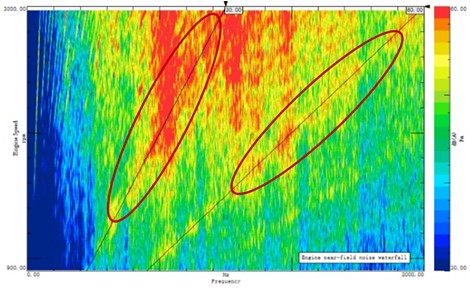
Two typical noise issues were identified. First, there is a gear rattle noise problem in the frequency band of 800 to 1400 Hz near the front-end gear train of the engine. Second, a noticeable gear whine is perceptible in the frequency band of 1500 to 2600 Hz, which is subjectively rated as unacceptable. microphones were placed near the engine to carry out an objective measurement of the noise, and the noise waterfall graph obtained from this testing is presented in Fig. 1.
Fig. 1Engine near-field noise waterfall chart
3. Modelling and analysis of the gear whine dynamics model
3.1. Modelling of gear whine dynamics model
The theoretical model of a gear system can effectively perform dynamic analysis and dynamic design. A gear system can be divided into two main parts: the transmission system and the structural system. The transmission system refers to the system composed of gear pairs, drive shafts, etc., which is used to transmit motion and power. The structural system, on the other hand, refers to the supports and housings that maintain the normal operation of the transmission system. For the transmission system, transfer matrices and the lumped parameter method, or the finite element method (FEM) can be considered; for the structural system, FEM is a necessity. When building an analytical model for the entire gear system, multiple modeling techniques can be integrated.
Fig. 2Timing gear system
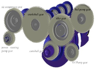
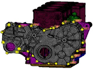
Fig. 3Analysis model of the engine powertrain
A comprehensive modeling of the gear system was carried out, which takes both the transmission system and the structural system within the gear system as the modeling objects. Therefore, this model is a multi-degree-of-freedom model that can consider the interaction between the two systems in the analysis, comprehensively determining the dynamic characteristics of the gear system. It can also study the dynamic meshing force and the dynamic transmission process from the gear teeth to the housing, as well as the vibration characteristics of the housing.
The timing gear system comprises the crankshaft gear, idler gear, camshaft gear, air compressor gear, power steering pump gear, fuel pump gear, oil pump gear, and the gear housing cover, as shown in Fig. 2.
The modal analysis model of the engine powertrain is illustrated in Fig. 3. Given that the front-end geartrain of the engine is the primary source of noise, the focus is on considering the impact of the front-end geartrain on engine noise, while features such as the intake and exhaust systems and cylinder head structures are neglected in the model processing. The finite element model predominantly employs second-order tetrahedral elements, with a total number of nodes amounting to 1,493,350 and a total number of elements reaching 966,957. The material for the shafts is defined as medium carbon steel, whereas the material properties of the remaining components are determined based on their actual usage materials. Bar elements are utilized to simulate bolt connections at the cylinder block, gear chamber, and cylinder head locations, whereas Rbe2 direct connections are applied at bolt hole areas of other components. The six degrees of freedom at the engine mount points are rigidly constrained.
3.2. Engine shell modal analysis
The analysis of the transmission paths for gear whine noise primarily investigates the pathways on the engine itself, to ascertain whether there is an overlap between the inherent frequency of the engine assembly and the meshing frequency of the gears, which could result in the amplification of the excitation. The modal analysis is depicted in Fig. 4.
The engine assembly exhibits a total of 219 modes within the 3000 Hz frequency range. Given that the whining noise predominantly occurs in the 800-1200 Hz band and near 1700 Hz, the analysis of these adjacent modal frequencies is prioritized. Comparison of test results with modal analysis results, it has been determined that the oil pan and gear housing significantly influence the modal characteristics and, consequently, the front-end noise levels.
Fig. 4Partial modal results of the engine assembly

a) Modes near the 800-1200 Hz range

b) Modes near 1700 Hz
3.3. Analysis of transmission error and contact pattern
Based on the dynamics analysis model, the transmission errors for each gear pair were calculated for typical operating conditions, as presented in Table 1.
The transmission errors of all gear pairs are relatively large. Among them, the crankshaft-idler gear pair, which has the largest transmission error, has a peak-to-peak (pk-pk) value of up to 4.410 μm, and the maximum value of the first-order harmonic component is 1.900 μm.
The main reason is the relatively small contact ratio of the crankshaft gear pair, with transverse contact ratio of 1.508 and a total contact ratio of 3.154. In terms of harmonic order, the first-order harmonic of the crankshaft-idler and air compressor-camshaft gear pairs are significantly large. Normally, the amplitude of the harmonic orders should typically exhibit an exponential decay trend, but the third-order harmonic of the crankshaft-idler and steering pump-air compressor gear pairs shows anomalies, indicating significant whining issues with the gears.
Table 1Transmission error of gear pair
Gear pair | Harmonic component (um) | pk-pk (um) | ||
1st | 2nd | 3rd | ||
Crankshaft – idler | 0.41 | 0.062 | 0.185 | 1.05 |
Camshaft – idler | 0.162 | 0.05 | 0.008 | 0.419 |
Air compressor – camshaft | 0.32 | 0.221 | 0.055 | 0.608 |
Power steering pump – air compressor | 0.065 | 0.019 | 0.044 | 0.101 |
Fuel pump – idler | 0.516 | 0.153 | 0.009 | 1.1 |
Oil pump – idler | 0.185 | 0.226 | 0.104 | 0.35 |
4. Optimization of engine whine noise
4.1. Structural modal optimization
The modal analysis results indicate that the modal frequencies of the oil pan and gear housing overlap with the frequencies of the whine noise, which significantly affects the front-end noise. Therefore, structural optimization is carried out for the oil pan and gear housing. Specifically, the optimization of the oil pan includes: 1) Widening, deepening, and extending the grooves in the oil pan to the fillet; 2) Appropriately compressing the sides and bottom inward. The optimization of the gear housing mainly includes: 1) Adding connections to the outside of the bolt holes; 2) Creating circular ring ribs and straight reinforcement ribs in certain areas of the inner surface of the gear housing cover, transitioning to the bolt holes; 3) Increasing bolt connections on the gear housing cover to enhance connection rigidity and suppress local modes; 4) Optimizing the local flange surface of the gear housing to improve connection rigidity.
The finite element model of the optimized gear housing and its cover is shown in Fig. 5. The local modes after optimization are shown in Fig. 6.
Fig. 5The FEM of the optimized gear housing and its cover
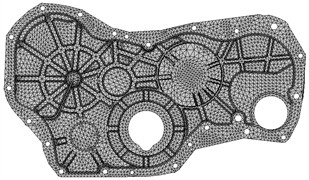
a) FEM of gear housing cover
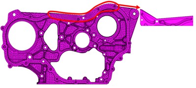
b) FEM of gear housing
Fig. 6Key vibration modes of modal analysis
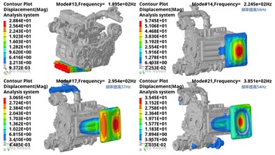
a) Vibration modes of the oil pan
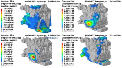
b) Vibration modes of the gear housing
Through optimization, the number of modes within 3000 Hz has been reduced by 23. The first local mode of the oil pan has been increased by 56 Hz; the first local mode of the gear housing front cover has been increased by 41 Hz.
4.2. Optimization of the Gear’s macro parameters
To address the issue of uneven contact forces and low contact ratio among the gears, it is necessary to increase the gear system’s contact ratio without altering the center distance. Due to the significant torque fluctuations in the front-end gear train, the axial constraint conditions of each shaft are relatively inferior compared to those of the gear shafts in a gearbox, and the helix angle should not be too large. The macro parameters modification results for the gears are detailed in Table 2.
After optimizing the number of teeth for the gear pair, there has been a noticeable improvement in the total contact ratio for each gear pair, with a significant increase in the face contact ratio and a slight decrease in the transverse contact ratio. The tooth thickness, after chamfering the gear addendum by 0.15 mm, is generally greater than 1 mm, meeting the design requirements.
Table 2Comparison of gear contact ratio before and after optimization
Gear pair | Original contact ratio | Optimization contact ratio | ||||
Transverse | Face | Total | Transverse | Face | Total | |
Crankshaft-idler | 1.508 | 1.674 | 3.154 | 1.997 | 1.468 | 3.465 |
Camshaft - idler | 1.787 | 1.674 | 3.434 | 2.936 | 1.468 | 4.404 |
Air compressor-camshaft | 1.632 | 1.367 | 2.999 | 2.113 | 1.219 | 3.333 |
Power steering pump - air compressor | 1.487 | 1.367 | 2.854 | 1.897 | 1.219 | 3.116 |
Fuel pump- idler | 1.68 | 1.367 | 3.048 | 2.542 | 1.219 | 3.761 |
Oil pump- idler | 1.574 | 0.7396 | 2.313 | 1.911 | 0.6594 | 2.571 |
4.3. Optimization of the Gear's micro parameters
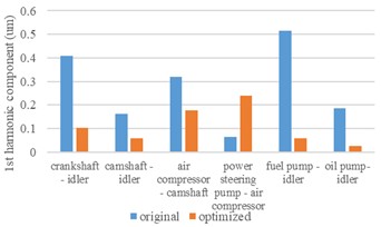
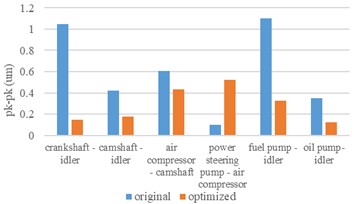
Based on the optimized macro parameters gear, the optimization of the gear’s microparameters is conducted. The microparameters mainly include profile crowning, lead crowning, profile inclination deviation, and lead inclination deviation. The microgeometric modification needs to consider the manufacturing tolerances during the gear machining process to ensure that the modified gears meet the corresponding tolerance ranges. The transmission error analysis results are illustrated in Fig. 7.
Fig. 7Comparison of transmission error before and after optimization
5. Experimental verification
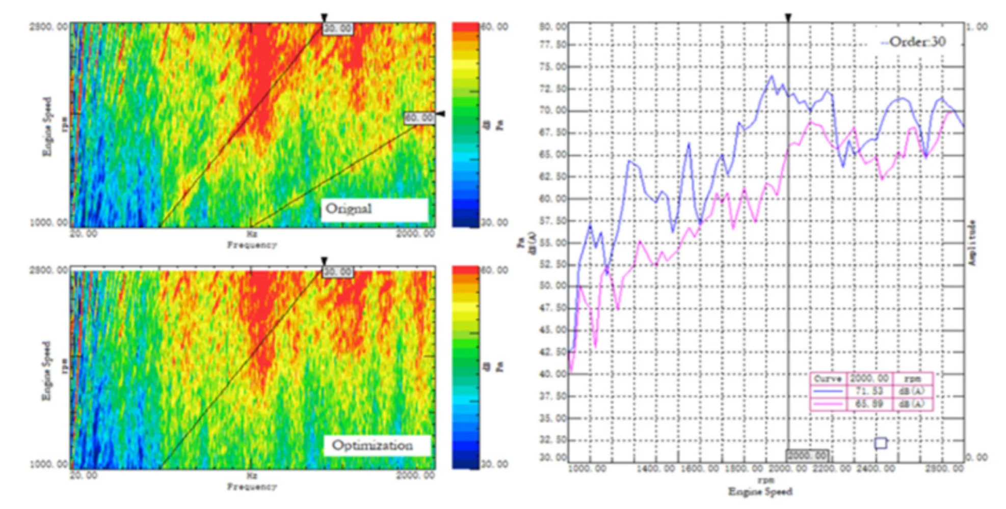
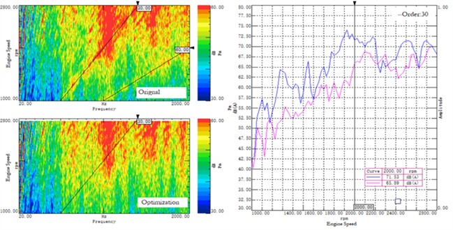
To verify the effectiveness of the optimization, it is essential to test the NVH performance and reliability of the gears. The samples are manufactured in accordance with the results of the gear modification and structural optimization of the gear housing. Following their production, experimental verification is conducted. As illustrated in Fig. 8, the noise test results indicate a significant improvement in the gear order noise after optimization, with the noise amplitude reduced by approximately 6 dB. The optimization effect is clear, and both subjective and objective performance criteria are satisfied in line with the design requirements.
Fig. 8Optimized engine noise waterfall chart
6. Conclusions
This paper addresses the gear whine issue observed in a passenger car engine during dynamometer tests, proposing analysis methods that consider the excitation source and transmission paths, including the optimization of macro and micro parameter design for gears, as well as structural optimization of the engine's oil pan and gear housing. The following conclusions are reached:
1) Gear misalignment from load imbalances causes transmission errors and gear whine. Solving this involves optimizing gear parameters: enhancing the contact ratio for smoother meshing and fine-tuning micro-parameters to correct misalignment. This ensures reliable performance and improved noise, vibration, and harshness (NVH) without sacrificing gear efficiency.
2) Engine assembly’s structural optimization should focus on enhancing rigidity and applying lightweight design to raise its natural frequency above the gear meshing frequency, ideally exceeding the first-order natural frequency.
References
-
M. Sun, C. Lu, Z. Liu, Y. Sun, H. Chen, and C. Shen, “Classifying, predicting, and reducing strategies of the mesh excitations of gear whine noise: a survey,” Shock and Vibration, Vol. 2020, No. 7, pp. 1–20, Aug. 2020, https://doi.org/10.1155/2020/9834939
-
G. Yue, W. Niu, J. Zhao, D. Kong, Y. Li, and H. Hou, “Gear whine resolution by tooth modification and multi-body dynamics analysis,” in SAE 2016 World Congress and Exhibition, Apr. 2016, https://doi.org/10.4271/2016-01-1061
-
P. K. Singh and S. A. R. K., “Study of effect of variation in micro-geometry of gear pair on noise level at transmission,” in Symposium on International Automotive Technology 2015, Jan. 2015, https://doi.org/10.4271/2015-26-0130
-
S. M. Jadhav, “Powertrain NVH analysis including clutch and gear dynamics,” in SAE 2014 World Congress and Exhibition, Apr. 2014, https://doi.org/10.4271/2014-01-1680
-
C. Chen, L. Zhu, J. Liu, D. Wei, and H. Yu, “Study and application of gear micro modification of electric drive system,” SAE International Journal of Passenger Vehicle Systems, Vol. 16, No. 1, pp. 3–17, Sep. 2022, https://doi.org/10.4271/15-16-01-0001
-
P. Lv, M. Zhang, T. Tang, X. Deng, J. Hu, and J. Lan, “Gear whine optimization of hybrid transmission based on dynamic excitation,” in Lecture Notes in Electrical Engineering, pp. 992–1003, Oct. 2022, https://doi.org/10.1007/978-981-19-3842-9_77
-
S. Lahoti, P. Patil, and J. J. Wagner, “Gear whine noise reduction by transmission error and contact pattern optimization: simulation and testing correlation,” in Noise and Vibration Conference and Exhibition, Aug. 2021, https://doi.org/10.4271/2021-01-1103
-
J. Chen, X. Kong, and P. Li, “Analysis of the control strategy of range extender system on the vehicle NVH performance,” Vibroengineering Procedia, Vol. 33, pp. 90–95, Oct. 2020, https://doi.org/10.21595/vp.2020.21681
About this article
The authors have not disclosed any funding.
The datasets generated during and/or analyzed during the current study are available from the corresponding author on reasonable request.
The authors declare that they have no conflict of interest.
