Abstract
The basic design parameters and operational conditions of an enhanced vibratory lapping machine are considered. The main purpose of the research is to define the influence of different machining regimes on the roughness parameters of flat surfaces of parts made of C22 steel. The experiments are carried out at different controllable conditions of the vibratory lapping process: amplitudes of vibrations of the upper lap, forced frequencies, machining durations, and lapping paste types. The obtained results are shown in the form of bar charts describing the dependencies of the surface roughness on the machining conditions mentioned above. The major scientific novelty consists in the further development of the technologies of lapping and polishing of flat surfaces using vibratory machines with an electromagnetic drive. The presented research can be used by engineers and technologists while improving existent designs of vibratory lapping-polishing machines, as well as enhancing the corresponding machining processes.
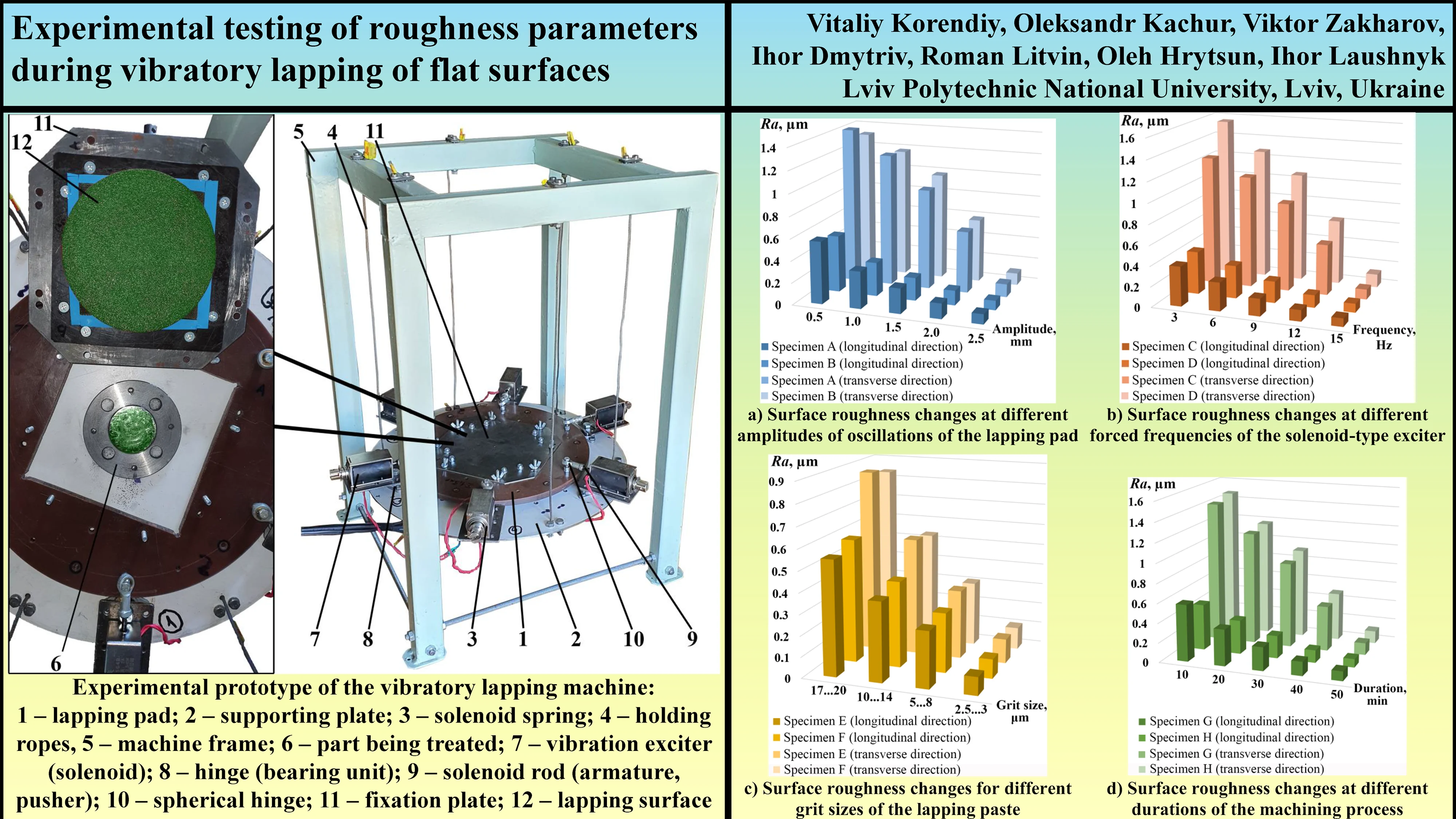
Highlights
- The study investigates the effects of vibratory lapping parameters, including amplitude, frequency, paste grit size, and duration, on the surface roughness of C22 steel.
- Increasing the oscillation amplitude of the lapping tool reduces surface roughness because it intensifies the removal of microscopic material layers.
- Higher oscillation frequencies also improve the surface finish by increasing the movement speed of the abrasive grains relative to the part's surface.
- Utilizing lapping pastes with finer grain sizes is crucial for achieving significantly smoother surfaces and higher finish classes.
- The applied vibratory lapping process successfully reduced the average initial surface roughness from a range of 1.4−1.6 μm down to 0.1−0.2 μm.
1. Introduction
The use of vibration technologies in the surface treatment of parts effectively eliminates surface micro-roughness, improving both smoothness and precision. These technologies also ensure even material distribution during processing, enhancing the quality of the final finish [1]. Currently, one of the most common methods for finishing flat surfaces is lapping, which enables high precision in geometric parameters and uniform surface roughness by controlled removal of microscopic layers of material [2], [3]. This process is widely employed in mechanical engineering to improve the performance of components, particularly their wear and corrosion resistance [4].
Lapping generally involves removing a thin layer of material from the surface using an abrasive slurry applied to the working surface of a lapping tool, which interacts with the part under external pressure and friction [5]. The process starts with preparing the parts, which must be clean and free from contaminants. Lapping tools are usually made of materials such as cast iron, copper, or bronze, which can hold the abrasive particles on their surface [6]. The abrasive slurry consists of an abrasive powder (e.g., silicon carbide or aluminum oxide) and a liquid medium that facilitates the even distribution of the abrasive particles across the surface of the lapping tool [7]. The slurry is applied to the tool, after which the part is pressed against it. The choice of abrasive material depends on the part's material and the required precision. The lapping process involves circular or linear motion of the part relative to the tool, where abrasive particles in the slurry remove microscopic layers of material from the surface of the part [8]. This continues until the desired surface precision and roughness are achieved.
An analysis of numerous sources, particularly those [2]-[14] dedicated to the technical and operational characteristics of lapping machines and the physical-mechanical properties of processed parts, suggests that planetary-type lapping machines are currently the most widely used for flat surface treatment of steel components. These machines consist of a central lapping plate with multiple tables rotating around both their own axis and the central plate, allowing for a complex movement that ensures even surface processing without localized wear [9]. Modern planetary machines allow the adjustment of various parameters, including the rotation speed of the central plate and tables, the pressure applied to the part, and the type and grit size of the abrasive material [10], [11]. This helps to optimize the process according to the material and dimensions of the part. However, planetary lapping machines have some drawbacks. Their complex design includes many moving parts that require regular maintenance, increasing the need for skilled personnel and operational costs [12]. Additionally, the cost of such equipment is typically too high for small or newly established enterprises. Optimal quality requires precise machine adjustments, and incorrect settings can lead to uneven wear or part damage [13], [14].
Due to these disadvantages, a number of vibratory lapping machines with circular trajectories of the lapping tools relative to the surface being machined have been proposed at the Lviv Polytechnic National University [15]-[19]. Some of these machines are equipped with electromagnetic drives [15]-[17], while more advanced models use solenoid-based vibration exciters [18], [19]. Most of the previous studies focused on the technical and operational parameters of these machines [18], such as dynamic and energy characteristics, as well as the development of control systems [19]. However, the technological aspects related to surface roughness, flatness, and the quality of the final finish were not extensively explored. Thus, the main goal of this study is to determine the influence of factors such as the amplitude and frequency of the working tool’s oscillations, the grit size of the lapping paste, and the processing duration on the surface roughness of steel components, using flanges made of C22 steel as an example.
2. Research methodology
To carry out the investigations, there was used an experimental model of a vibration lapping machine developed at Lviv Polytechnic National University (see Fig. 1 [18], [19]). The main working element is the lapping pad 1. The plate 2 is supported from the frame 5 by six holding ropes 4 and is used for installing all the components of the machine and parts 6 being treated.
Fig. 1Experimental prototype of the vibratory lapping machine: 1 – lapping pad; 2 – supporting plate; 3 – solenoid spring; 4 – holding ropes, 5 – machine frame; 6 – part being treated; 7 – vibration exciter (solenoid); 8 – hinge (bearing unit); 9 – solenoid rod (armature, pusher); 10 – spherical hinge; 11 – fixation plate; 12 – lapping surface
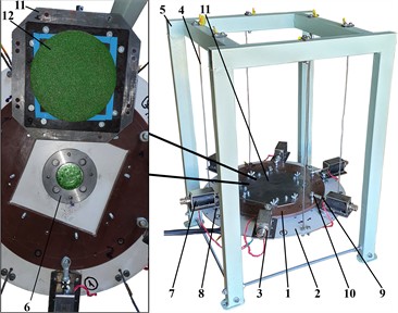
The vibration exciter 7 consists of the solenoid whose armature (pusher) 9 is connected to the lapping pad 1 with the help of the spherical joint 10. On the opposite ends of the solenoid pushers 9, there are installed the springs 3 eliminating their displacements relative to the solenoid bodies. In order to generate the circular oscillatory motion of the lapping pad 1, the exciters 7 are installed on the supporting plate 2 with the help of bearing units 8. To the plate 11, there is fixed the lapping surface 12 made of fabric-based laminate (textolite) and covered with the lapping paste. The machining process is carried out due to the friction and wear phenomena caused by the circular oscillatory motion of the part relative to the lapping surface, which are in contact.
Table 1Main parameters of the lapping process used during the experimental research
Parameter | Characteristics | Parameter | Characteristics |
Material of the lapping surface | Fabric-based laminate (textolite) TK-5 | Amplitude of the lap oscillations, mm | 0.5; 1; 1.5; 2; 2.5 |
Specific pressing force of the lap, kPa | 8.5…9 | Grit size of the lapping paste, μm | 2.5…3; 5…8; 10…14; 17…20 |
Forced frequency of the solenoid, Hz | 3; 6; 9; 12; 15 | Duration of the machining process, min | 10; 20; 30; 40; 50 |
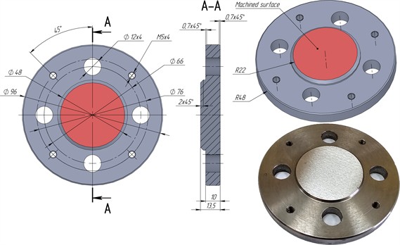
The test specimens used in the experiments were hydraulic flanges (Fig. 2), made of C22 steel. The lower surface of the flange was fixed to the suspended platform of the lapping machine, while the upper protruding flat surface was subjected to treatment through the circular oscillations of the upper lapping tool. The main parameters of the lapping process, which were employed during the experimental studies, are shown in Table 1. Specifically, the amplitude of the lapping tool's oscillations varied from 0.5 mm to 2.5 mm at a maximum excitation frequency of 15 Hz, with a minimum grit size of the lapping paste ranging from 2.5 to 3 μm, and the duration of the treatment of 50 min. The second study was conducted with varying excitation frequencies, ranging from 3 Hz to 15 Hz, while maintaining the maximum oscillation amplitude of 2.5 mm and all other conditions identical. The third study involved the use of different lapping pastes (No. 1, No. 2, No. 3, No. 4) with grit sizes of 2.5…3 μm, 5…8 μm, 10…14 μm, and 17…20 μm, respectively, under a maximum excitation frequency of 15 Hz, an oscillation amplitude of 2.5 mm, and a processing duration of 50 min. In the final study, the duration of the treatment was varied between 10 and 50 min, with a frequency of 15 Hz, an amplitude of 2.5 mm, and the fine-grit paste No. 1 characterized by the grit size of 2.5…3 μm.
Fig. 2General design of the part being machined
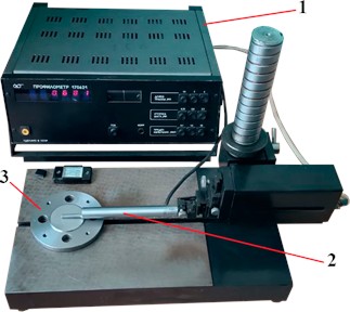
Given that the surfaces of the parts under study were initially subjected to flat grinding, their roughness in the longitudinal and transverse directions (relative to the movement of the grinding wheel) was initially different. Therefore, roughness measurements of the surfaces treated under the aforementioned processing parameters were carried out in two mutually perpendicular directions using a standard profilometer of model 176021 (Fig. 3), which is available at the Karpenko Physico-Mechanical Institute of the National Academy of Sciences of Ukraine. Eight pre-treated (pre-ground) parts were used to thoroughly analyze their roughness parameters under four different machining conditions described above.
Fig. 3Experimental testing of the roughness parameters: 1 – profilometer of the 176021 model; 2 – stand (holder) with a sensing needle (stylus); 3 – machined part
3. Results and discussion
As previously mentioned, the surfaces of the studied parts were initially subjected to flat grinding. Therefore, a series of roughness measurements in both the longitudinal and transverse directions (relative to the movement of the grinding wheel) was conducted to establish baseline data for further study of the lapping process. The corresponding results are presented in Fig. 4 for the eight experimental specimens (A, B, C, D, E, F, G, H) and five tests for each specimen and each direction. Overall, the average surface roughness in the longitudinal direction ranges from 0.4 µm to 0.6 µm, while in the transverse direction, it varies from 1.4 µm to 1.6 µm.
Fig. 4Roughness parameters of the pre-ground specimens

Fig. 5(a) illustrates the results of a study on the effect of the lapping tool’s oscillation amplitude, which varied from 0.5 mm to 2.5 mm, on the surface roughness of the treated parts. The experiment was conducted at a maximum excitation frequency of 15 Hz, with the finest lapping paste (characterized by the grit size of 2.5 to 3 µm) and a processing duration of 50 min. It is evident that increasing the oscillation amplitude of the lapping tool, i.e., the radius of its circular trajectory, leads to a reduction in surface roughness. This occurs because the increase in amplitude results in higher linear velocities of the lapping tool’s points and abrasive grains, intensifying the removal of microscopic layers from the treated surfaces [2], [5], [11]. On the other hand, increasing the oscillation amplitude will also cause a nonlinear rise in the power consumed by the vibration machine [18], [19], negatively affecting its operational efficiency. Thus, the feasibility of increasing the oscillation amplitude to improve the surface finishing process requires further investigation and justification.
The following study was conducted under varying excitation frequencies ranging from 3 Hz to 15 Hz, with a maximum oscillation amplitude of the lapping pad of 2.5 mm, a maximum machining duration of 50 min, and the finest lapping paste with a grit size of 2.5 to 3 µm. The corresponding surface roughness measurements are presented in Fig. 5(b). It is clear that increasing the oscillation frequency of the lapping tool leads to an increase in the movement speed of the abrasive grains relative to the treated surface. This, in turn, enhances the smoothing of surface irregularities and reduces surface roughness [3], [4], [6]. However, the feasibility of increasing the oscillation frequency to improve lapping quality requires further investigation, taking into account other operational factors, particularly the machine's power consumption.
Fig. 5Results of experimental investigations of the influence of different machining conditions on the surface roughness of parts made of C22 steel
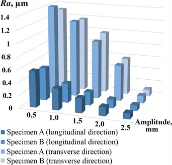
a) Surface roughness changes at different amplitudes of oscillations of the lapping pad
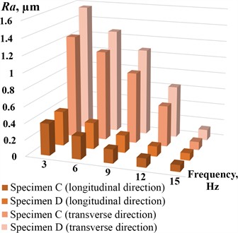
b) Surface roughness changes at different forced frequencies of the solenoid-type exciter
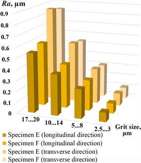
c) Surface roughness changes for different grit sizes of the lapping paste
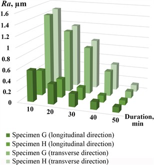
d) Surface roughness changes at different durations of the machining process
The third study (Fig. 5(c)) involved the use of various lapping pastes with grit sizes of 2.5…3 µm, 5…8 µm, 10…14 µm, and 17…20 µm, respectively, under a maximum excitation frequency of 15 Hz, an oscillation amplitude of 2.5 mm, and a processing duration of 50 minutes. Given that the surfaces of the test parts had already undergone flat grinding, with a maximum roughness not exceeding 2 µm, reducing the grit size of the lapping paste naturally resulted in a smoother surface under the same conditions [5], [11], [13]. However, further justification is required regarding the use of pastes with different grit sizes for the treatment of surfaces that have not been pre-treated or have undergone rough machining during planning, milling, or grinding.
The results of experimental studies on the effect of processing duration, which ranged from 10 to 50 minutes, on the surface roughness under a maximum excitation frequency of 15 Hz, an oscillation amplitude of 2.5 mm, and the use of fine-grain lapping paste with a grit size of 2.5 to 3 µm are shown in Fig. 5(d). Predictably, increasing the duration of the lapping process leads to a reduction in surface roughness due to a higher number of cycles for removing microscopic layers of material [2], [5]. However, excessively long processing without replacing the lapping paste results in a decrease in the lapping intensity [6], which would require additional time and energy to achieve the desired surface finish [17], [19]. Therefore, selecting an optimal processing time and determining the appropriate frequency for replacing the lapping paste under specific lapping conditions remain important issues that require further investigation.
4. Statistical processing of the experimental data
First of all, it is necessary to mention that in these studies, it is impossible to ensure repeatability of experiments on a single workpiece due to changes in surface roughness. Once experimental tests have been conducted, the machined workpiece cannot be returned to its initial conditions. Therefore, four single-factor experiments without replication were conducted, followed by a corresponding regression analysis of the obtained results.
Fig. 6Regression models describing the experimental data
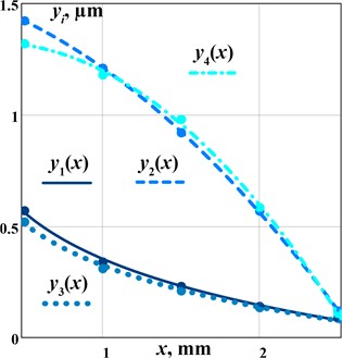
a) Surface roughness changes at different amplitudes of oscillations of the lapping pad
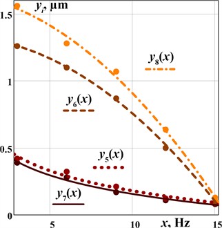
b) Surface roughness changes at different forced frequencies of the solenoid-type exciter
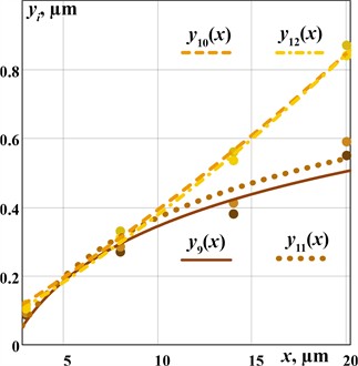
c) Surface roughness changes for different grit sizes of the lapping paste
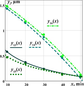
d) Surface roughness changes at different durations of the machining process
The corresponding regression models of the obtained results of each experiment are presented in Table 2 and Fig. 6. The models describing changes in surface roughness in the longitudinal direction are characterized by logarithmic relationships, while the corresponding regression models for transverse roughness are described by polynomial dependencies.
To evaluate the adequacy of the fitted models, we employed a standard procedure involving Fisher’s -test. The calculated -statistics, computed using STATISTICA 12.0 software, yielded the values of presented in Table 2. Comparing these values to the tabulated -value of 161.4 for degrees of freedom 1 and 1, we observe that is less than for all the experimental tests, thus confirming the adequacy of the corresponding regression models.
Table 2Results of statistical processing of the experimental data
Specimen | Regression model | Calculated F-statistics |
Specimen A (longitudinal direction) | 35.739 | |
Specimen A (transverse direction) | 156.01 | |
Specimen B (longitudinal direction) | 34.232 | |
Specimen B (transverse direction) | 50.279 | |
Specimen C (longitudinal direction) | 55.205 | |
Specimen C (transverse direction) | 90.607 | |
Specimen D (longitudinal direction) | 116.55 | |
Specimen D (transverse direction) | 97.901 | |
Specimen E (longitudinal direction) | 135.06 | |
Specimen E (transverse direction) | 136.13 | |
Specimen F (longitudinal direction) | 154.72 | |
Specimen F (transverse direction) | 139.72 | |
Specimen G (longitudinal direction) | 46.872 | |
Specimen G (transverse direction) | 111.08 | |
Specimen H (longitudinal direction) | 116.70 | |
Specimen H (transverse direction) | 156.49 |
5. Conclusions
For the vibration finishing machine developed at Lviv Polytechnic National University, the influence of the oscillation amplitude and excitation frequency of the lapping tool, as well as the grain size of the lapping paste and the processing duration, on the surface roughness of flat parts (flanges) made of C22 steel was studied. It was established that surface roughness decreases non-linearly with an increase in the oscillation amplitude of the lapping tool, meaning the radius of its circular trajectory, as well as with an increase in the excitation frequency and processing duration. Additionally, the reduction of surface roughness and the achievement of higher surface finish classes were ensured by using lapping pastes with finer grain sizes. For the studied parts, where the average surface roughness after initial flat grinding was within the range of 1.4,…, 1.6 µm, the use of various excitation conditions and lapping pastes with different grain sizes allowed the roughness to be reduced to 0.1,…, 0.2 µm. Among the prospects for further research on this topic, key areas include determining the optimal processing duration and frequency of lapping paste replacement for specific lapping conditions, as well as selecting the appropriate excitation parameters for the lapping tool, taking into account the potential power consumption of the vibration machine given predefined surface finish requirements.
References
-
V. Borovets, O. Lanets, V. Korendiy, and P. Dmyterko, “Volumetric vibration treatment of machine parts fixed in rotary devices,” in Lecture Notes in Mechanical Engineering, Cham: Springer International Publishing, 2021, pp. 373–383, https://doi.org/10.1007/978-3-030-68014-5_37
-
W. L. Cong, P. F. Zhang, and Z. J. Pei, “Experimental investigations on material removal rate and surface roughness in lapping of substrate wafers: a literature review,” Key Engineering Materials, Vol. 404, pp. 23–31, Jan. 2009, https://doi.org/10.4028/www.scientific.net/kem.404.23
-
A. Deaconescu and T. Deaconescu, “Improving the quality of surfaces finished by lapping by robust parameter design,” Journal of Economics, Business and Management, Vol. 2, No. 1, pp. 1–4, Jan. 2014, https://doi.org/10.7763/joebm.2014.v2.88
-
L. E. A. Sanchez, N. Z. X. Jun, and A. A. Fiocchi, “Surface finishing of flat pieces when submitted to lapping kinematics on abrasive disc dressed under several overlap factors,” Precision Engineering, Vol. 35, No. 2, pp. 355–363, Apr. 2011, https://doi.org/10.1016/j.precisioneng.2010.09.012
-
H. Y. Tam, H. B. Cheng, and Y. W. Wang, “Removal rate and surface roughness in the lapping and polishing of RB-SiC optical components,” Journal of Materials Processing Technology, Vol. 192-193, pp. 276–280, Oct. 2007, https://doi.org/10.1016/j.jmatprotec.2007.04.091
-
M. Farahnakian and H. Shahrajabian, “Experimental study on surface roughness and flatness in lapping of AISI 52100 steel,” International Journal of Advanced Design and Manufacturing Technology, Vol. 9, No. 2, pp. 61–68, 2016.
-
B. Pan, R. Kang, X. Zhu, D. Du, W. Huang, and J. Guo, “Formation mechanism of concave and convex surface shapes in double-sided lapping,” Journal of Materials Processing Technology, Vol. 309, p. 117749, Nov. 2022, https://doi.org/10.1016/j.jmatprotec.2022.117749
-
L. Yang, X. Guo, R. Kang, X. Zhu, and Y. Jia, “Effect of kinematic parameters considering workpiece rotation on surface quality in YAG double-sided planetary lapping with the trajectory method,” The International Journal of Advanced Manufacturing Technology, Vol. 123, No. 7-8, pp. 2679–2690, Nov. 2022, https://doi.org/10.1007/s00170-022-10288-y
-
J. Guo et al., “Stress-induced deformation of thin copper substrate in double-sided lapping,” Chinese Journal of Mechanical Engineering, Vol. 36, No. 1, p. 15, Feb. 2023.
-
L. Zhao et al., “A real-time dressing method for metal lapping pads based on the thermal deformation effect,” The International Journal of Advanced Manufacturing Technology, Vol. 120, No. 1-2, pp. 945–958, Feb. 2022, https://doi.org/10.1007/s00170-022-08869-y
-
Z. Geng, P. Zhou, L. Meng, Y. Yan, and D. Guo, “Prediction of surface profile evolution of workpiece and lapping plate in lapping process,” Journal of Manufacturing Science and Engineering, Vol. 144, No. 8, p. 08100, Aug. 2022, https://doi.org/10.1115/1.4053279
-
Z. Wang et al., “A novel technique for dressing fixed abrasive lapping pad with abrasive water jet,” International Journal of Precision Engineering and Manufacturing-Green Technology, Vol. 10, No. 6, pp. 1351–1373, Jan. 2023, https://doi.org/10.1007/s40684-022-00500-5
-
C. Micallef, K. Walton, Y. Zhuk, and A. I. Aria, “Surface finishing and residual stress improvement of chemical vapour deposited tungsten carbide hard coatings by vibratory polishing,” Surface and Coatings Technology, Vol. 439, p. 128447, Jun. 2022, https://doi.org/10.1016/j.surfcoat.2022.128447
-
J. Kundrák, M. Morgan, A. V. Mitsyk, V. A. Fedorovich, and A. I. Grabchenko, “Mathematical simulation of the vibration treatment of parts in a liquefied abrasive working medium,” The International Journal of Advanced Manufacturing Technology, Vol. 120, No. 7-8, pp. 5377–5398, Mar. 2022, https://doi.org/10.1007/s00170-022-08843-8
-
V. Korendiy, V. Zakharov, V. Gurey, P. Dmyterko, I. Novitskyi, and O. Havrylchenko, “Modelling the operation of vibratory machine for single-sided lapping of flat surfaces,” Vibroengineering Procedia, Vol. 38, pp. 1–6, Jun. 2021, https://doi.org/10.21595/vp.2021.22001
-
V. Korendiy, O. Kachur, V. Zakharov, I. Kuzio, O. Havrylchenko, and T. Hurey, “Dynamics and control of vibratory finishing machine with translational motion of lapping-polishing plates,” Vibroengineering Procedia, Vol. 44, pp. 8–14, Aug. 2022, https://doi.org/10.21595/vp.2022.22842
-
V. Korendiy, O. Kachur, V. Zakharov, I. Kuzio, I. Hurey, and R. Predko, “Experimental study of the lap motion trajectory of vibratory finishing machine,” Vibroengineering Procedia, Vol. 46, pp. 1–7, Nov. 2022, https://doi.org/10.21595/vp.2022.23002
-
V. Korendiy, O. Kachur, V. Zakharov, and I. Kuzio, “Studying the dynamics of a vibratory finishing machine providing the single-sided lapping and polishing of flat surfaces,” Engineering Proceedings, Vol. 24, No. 1, Sep. 2022, https://doi.org/10.3390/iecma2022-12898
-
V. Korendiy, O. Kachur, and V. Zakharov, “Development of a control system for a vibratory lapping-polishing machine,” in IEEE XXVIII International Seminar/Workshop on Direct and Inverse Problems of Electromagnetic and Acoustic Wave Theory (DIPED), pp. 233–237, Sep. 2023, https://doi.org/10.1109/diped59408.2023.10269520
About this article
The authors have not disclosed any funding.
The datasets generated during and/or analyzed during the current study are available from the corresponding author on reasonable request.
The authors declare that they have no conflict of interest.
