Abstract
To solve the problem of maximizing space utilization of car folding seats within limited spatial constraints, a design method for space-maximizing four-bar folding seat hinges is proposed. First, we will investigate the existing types of car folding seats, identify the mainstream configurations, and determine the optimal position of the four-bar linkage hinge point based on the constraints present within the car using theoretical analysis methods. Secondly, kinematic and dynamic models of the four-bar linkage mechanism are established, followed by the formulation of kinematic and dynamic equations. Finally, numerical methods are employed to solve these equations and obtain the kinematic and dynamic characteristics. The results indicate that the design method proposed in the article, which aims to maximize the space of the hinge four-bar folding seat, is efficient and feasible. This approach optimizes the utilization of interior space and enhances passenger comfort while accommodating the folding function of the seat within the existing vehicle environment. This method holds significant engineering implications for the design of folding seats in similar types of vehicles.
Highlights
- To solve the problem of maximizing the space utilization of car folding seats under limited space constraints, a theoretical design method for space maximizing hinge four-bar folding seats is proposed.
- The position of the hinge point of the four-bar linkage is determined by theoretical analysis, and the static and dynamic mechanical characteristics of the four-bar linkage mechanism are obtained using an analytical model.
- This method has been successfully applied in the design of the third row folding seats of a certain car.
1. Introduction
With the improvement of people’s living standards, the comfort of a car has become a significant factor for individuals when selecting a car, and the interior space plays a crucial role in determining that comfort. The seat is a crucial component of the car, occupying the largest space in the car. Its primary function is to provide convenient, comfortable, and safe driving seats for both the driver and passengers. Folding seats can effectively enhance interior space and improve car comfort. Consequently, developing folding seats has become a crucial area of research for automotive technicians.
In recent years, automotive technicians have conducted extensive research on folding seats. Nuraresya, Ibun et al. reviewed the research and development of children’s car seats from 1988 to 2018, and proposed an implementation plan for height increasing seats in children’s cars [1]. Jiang Xiaoshuo et al. combined ergonomics and morphological elements to design a child seat structure, and compared and evaluated the collision model motion response with the measured motion response [2]. García Nieto, P. J. et al. designed the rear seat of the car, including the adjustable frame and foam rubber, and tested the seat performance through the finite element method [3]. Liu Xinyang and colleagues utilized ergonomic principles to design a car folding mechanism and validated its engineering specifications through numerical simulations [4]. Cheng Yu et al. employed mechanical principles to design a multi-link folding seat and presented its kinematic and dynamic characteristics [5]. This research presents various innovative designs for folding seats, contributing to the effective utilization of interior space and enhancing passenger comfort. However, none of these studies address the design of folding seats for cars with specific spatial constraints within the interior.
This article focuses on the design of the third-row seats in a specific car model, and proposes a hinge four-bar folding seat design method that optimizes space utilization. First, based on the constraints of the interior space and the parameters for seat, the positions of each hinge point in the four-bar linkage mechanism are determined. Next, the kinematic and dynamic models of the four-bar linkage mechanism are established, along with the corresponding kinematic and provide dynamic equations. Finally, utilize numerical calculation methods to develop programs that determine kinematic and dynamic characteristics. This research method can serve as a valuable reference for the design of folding seats in similar types of cars.
2. Design of seat folding mechanism
2.1. Types of folding seats
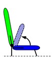
There are various types of folding seat designs [6]. Research on existing folding mechanisms has identified, the primary types of folding seats as illustrated in Fig. 1. From Fig. 1, it is evident that different types of folding seats exhibit significant variations in their folding mechanisms and the space required for folding. Notably, Fold back and Stowable seats have significant advantages over other types of folding seats in terms of cost, weight, space efficiency, ease of operation, and compatibility with the vehicle structure. They are currently widely used in automotive folding seats. Compared with Stowable seats, Fold back seats have a simpler structure and advantages in terms of cost and weight. In contrast, Stowable seats feature a more complex design but offer greater benefits in folding space and compatibility with the body. Currently, the design program for Fold back seats is relatively mature, while the design program for Stowable seats has to be perfected.
Fig. 1Types of folding seats
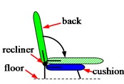
a) Fold back
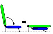
b) Stowable
c) Stadium
d) Fold to side
e) Fold into tub
f) Flip 180° and fold
g) Split fold flat
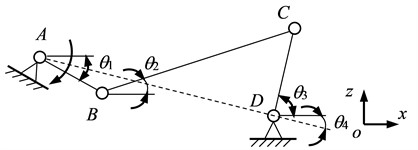
Fig. 2Simplified model of hinge four-bar linkage seat folding mechanism
2.2. Folding mechanism design
Ordinary folding seats are typically folded using angle adjusters, folders, riveting, and other methods. In contrast, the folding function of stowable seats is primarily achieved through a four-bar linkage mechanism with hinges. This design maximizes the use of interior space, enhances reliability and comfort, and effectively meets the requirements for seat folding while accommodating the existing vehicle environment.
According to the design requirements, the third-row seats must have a folding function, and the backrest of the folded seats should be horizontal and aligned with the height line of the luggage compartment. Based on this analysis, selecting Stowable seats can meet the design requirements. Next, we will design a four-bar linkage folding mechanism for Stowable seat hinges.
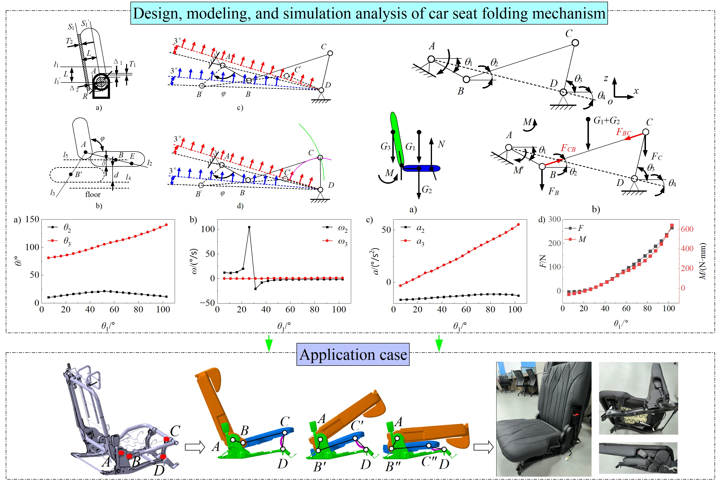
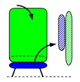
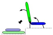
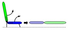
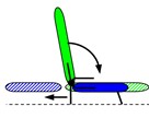
Based on the overall layout of the car body, seat parameters, and dummy data, a simplified model of the four-bar linkage mechanism for the third-row seat hinge of this car has been established, as illustrated in Fig. 2. In this model, point A represents the rotation center of the backrest, which remains fixed when the backrest is folded down. Point B serves as the rotation center of the seat cushion, which rotates around point A in relation to the backrest. Point C is the rotation center on the front link, indicating the seat cushion’s rotation relative to the front link, and it moves with the seat cushion around point D. Finally, point D is the lower rotation center of the front link, which is the fixed position for the front link′s rotation center.
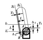
1) The method for determining point A: it is illustrated in Fig. 3(a). Assuming that the backrest adjustment utilizes the angle adjuster method (other adjustment methods can be analogized), the minimum distance L from point A to the backrest backboard is as follows:
where, R represents the radius of the angle adjuster; Δ1 denotes the gap between the angle adjuster and the angle adjuster cover; T1 indicates the thickness of the angle adjuster cover; Δ2 refers to the gap between the backplate and the angle adjuster cover; and T2 signifies the thickness (including carpet thickness).
After the backrest is folded down, the design necessitates that the height line of the backrest aligns with the height line of the luggage compartment. Consequently, point A must be positioned on the straight line l'1, which lowers the luggage compartment height line l1 by a distance L. Next, shift plane S1, located on the exterior of the backboard, forward by a distance L to create plane S'1. The intersection of straight line l1 and plane S'1 defines point A.
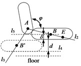
(2) Method for Determining point B: Point B serves as the connection point between the backrest and the seat cushion, as well as the rotation center of the seat cushion in relation to the backrest. Point B rotates around Point A with the seat cushion, causing the seat cushion to sink. If the amount of sinking of the seat cushion is denoted as d, then the sinking amount of Point B is also D.
(As illustrated in Fig. 3(b)), select point E in the design area. Connect point A to point E to create line l2. Rotate line l2 clockwise around point A to adjust the backrest angle φ to resulting in line l3. Next, draw a horizontal line l4 for the maximum sinking position of the seat cushion. Move line l4 upward by a distance of d+δ to create line l5. The intersection of l2 and l5 determines the initial position of point B. Subsequently, adjust point B based on factors such as foam thickness and skeleton structure to establish the corrected position of point B.
(3) Method for Determining Point D: The height of the vehicle floor at the third-row seats is typically elevated, which often results in a situation where the seat cushion cannot continue to sink due to the constraints of the vehicle floor. The common solution is to reduce the height of the seat cushion to eliminate the and it may bring the risk of reduced comfort. Therefore, the design of point D needs to meet the requirements of structural design, sufficient seat cushion sinking, and avoid interference with the vehicle floor. While a lower height is preferable, it is essential to prevent the occurrence of mechanical motion jamming caused by the collinearity of points A, B, and D.
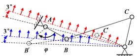
(4) Method for Determining Point C: Based on the above method, the positions of points A, B, and D have been largely established. When determining the position of point C, the primary consideration is to prevent the four-bar linkage mechanism from becoming stuck within the limited adjustment angle of the backrest. Specifically, it is essential to avoid a scenario where three points become collinear during the backrest adjustment process. Therefore, when establishing the position of point C, a reverse design method can be employed. This method first identifies the motion state of the four-bar linkage when the backrest is folded down, and then works backward to determine the design position.
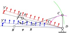
As illustrated in Fig. 3(c), point A and D serve as fixed hinge points. When the backrest is folded down, point B rotates around point A by a certain angle φ, moving to point B′. Simultaneously, point C rotates around point D to reach its the lower limit position at point C′. To prevent collinearity among points B′, C′, and D, point C′ should be positioned above the line; To avoid collinearity between points A, C′, and D, point C′ should be situated above the line connecting points A and D. Considering safety margins, a clearance of 3 should be maintained above the line connecting points D and B′, as well as above the line connecting points A and D. The optimal position for point C′ is within the area indicated by the red line and arrow in Fig. 3(c). To maximize the utilization of seat space under the existing boundary conditions, the seat cushion should be lowered as much as possible to the lower limit position. From the analysis above, it is evident that the greater the height difference between point C and point C′, the more of the seat cushion can be lowered. Therefore, the position of point C should be as high as possible, while the position of point C′ should be as low as possible.
As shown in Fig. 3(d), point C′ is selected near the red line. After selecting point C′, the length of the connecting rod is determined. First, draw an arc with point B as the center and a radius equal to B′C′. Then, draw another arc with point D as the center and a radius equal to DC′. The intersection point of the two arcs indicates the position of point C.
Fig. 3Method for determining the rotation center of a four-bar linkage mechanism with a hinge
a)
b)
c)
d)
Fig. 4Schematic diagram of force analysis of four-bar linkage mechanism with hinge
a)
b)
3. Analysis of seat folding mechanism
3.1. Kinematic analysis
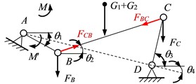
Using the coordinate system illustrated in Fig. 2, establish a kinematic analysis model for the four-bar linkage mechanism of the hinge, as shown in Fig. 2. In the Fig. 2, θ1 is the angle between the active connecting rod AB and the positive direction of the x-axis, θ2 denotes the angle between the connecting rod BC and the positive direction of the x-axis, θ3 indicates the angle between the passive connecting rod CD and the positive direction of the x-axis, and θ4 signifies the angle between the frame AD and the positive direction of the x-axis.
Using the complex vector method for kinematic analysis of the model, the complex vector equation is [7]:
By substituting Euler’s formula eiθj=cosθj+isinθj into Eq. (2), we obtain:
According to the analysis in Section 2.2 above, the initial coordinates of points A, B, C, and D are known, where points A and D are fixed hinge points and points B and C are moving hinge points. Combined with the fixed length of each rod, the coordinates of hinge points B and C at different motion positions, as well as θ1, θ2, θ3, θ4can be calculated. By taking the derivative of Eq. (3) once and twice, the angular velocity and angular acceleration of each rod can be calculated.
3.2. Kinetic analysis
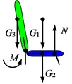
In the design state, the seat is tilted backward, and the force distribution on the seat is illustrated in Fig. 4(a). G1, G2, and G3 represent the weights of the passenger, seat cushion, and backrest, respectively. N denotes the support force exerted by the floor on the seat, while M indicates the required restoring torque for seat adjustment. The folding mechanism is the focus of this study, and its force distribution in the backward-tilting state is shown in Fig. 4(b). M' represents the driving torque for seat folding, while FB and FC are the vertical force components of gravity at points B and C, respectively. FBC and FBC are the tensile forces exerted at points C and B, respectively. The force balance equation for hinge point D is:
The force balance equation for hinge point A is:
Based on the vertical force distribution at hinge points B and C, and ignoring the displacement of the center of mass of the passenger and seat cushion, it can be concluded that:
Substituting Eq. (6) into Eqs. (4) and (5) yields:
The required restoring torque for the backrest is:
where, LAO is the distance from point A to the center of mass of the backrest.
Substituting Eq. (7) into Eq. (8) yields:
4. Application case
To verify the feasibility of the above design method, the folding mechanism of the third-row seats of a specific car has been designed and analyzed. The design parameters of the vehicle body and seats are presented in Table 1.
According to the method for determining points A, B, C, and D in section 2.2, combined with the relevant parameters and seat boundary conditions presented in Table 1, the positions of each hinge point of the four-bar linkage are projected onto the xoz plane to obtain the coordinates of each hinge point: A (–3116.0, –43318.1), B (–3034.5, –43291.6), C (–2743.7, –43362.1), and D (–2753.8, –43247.9). Using MATLAB software, numerical calculations were performed on the kinematic and dynamic equations of the four-bar linkage mechanism [8]. The kinematic and dynamic characteristics of the four-bar linkage mechanism were obtained, as illustrated in Fig. 5. The results of the kinematic analysis can be utilized to calculate and control the degree of rapid return characteristics of the four-bar linkage mechanism, while the results of the dynamic analysis can inform the selection of manual adjustment forces or electric folding seat drive motors.
Table 1Body and seat design parameters
Parameters | Specifications | Parameters | Specifications |
Seat size/ l×b×w (mm) | 732×467×683 | H-point coordinates / (x,y,z) (mm) | (–2994, –250, 393) |
Passenger mass / m1 (kg) | 70 | Recliner radius / R (mm) | 33 |
Seat cushion mass / m2(kg) | 9.5 | Thickness of recliner cover / T1 (mm) | 2.5 |
Backrest mass / m3(kg) | 7.5 | Gap between backboard and recliner / Δ2 (mm) | 17.5 |
Backrest design angle / α (º) | 109 | Backboard thickness / T2 (mm) | 0.4 |
Distance from point A to the center of mass of the backrest / LAO (mm) | 40 | Gap between the recliner and the recliner cover / Δ1 (mm) | 12.2 |
Seat cushion height above the floor / H1 (mm) | 70.5 | Active connecting rod angle range / θ1 (°) | [18, 106] |
Height of luggage from the floor / H2(mm) | 198.3 | Active connecting rod angular velocity / ω1 (°/s) | 1 |
Fig. 5Kinematic and dynamic characteristics of folding mechanism
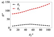
a) Rotation angle curve
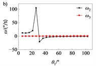
b) Angular velocity curve
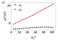
c) Angular acceleration curve
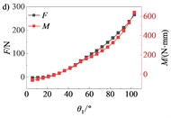
d) Force and torque curves
Fig. 6Seat folding mechanism movement trajectory diagram
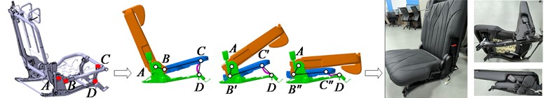
Using CATIA software, the three-dimensional structure of the hinged four-bar folding seat was designed, and the DMU module was utilized for motion analysis. The resulting motion trajectory diagram is presented. Fig. 6 reveals that the numerical results obtained from MATLAB align closely with those derived from CATIA/DMU. This indicates that the design method aimed at maximizing the space of the hinged four-bar folding seat, as proposed in the explanatory text, possesses of high degree of credibility.
5. Conclusions
This article investigates existing types of car seat folding mechanisms, clarifies the predominant forms of contemporary car seat folding, and proposes a space-maximizing car seat folding mechanism based on a four-bar linkage hinge design. Through a combination of theoretical analysis, numerical calculations, and 3D modeling, the kinematic and dynamic characteristics of the seat folding mechanism are analyzed. The design aims to optimize the use of car interior space and enhance passenger comfort while fulfilling the functional requirements of seat folding and existing body environments.
References
-
I. Nuraresya, U. Nirmal, and P. K. Ng, “A comprehensive review on the development of car booster seats for children,” Current Journal of Applied Science and Technology, Vol. 38, No. 1, pp. 1–21, Oct. 2019, https://doi.org/10.9734/cjast/2019/v38i130345
-
X. Jiang and X. Meng, “A structural design of a child seat based on morphological elements and ergonomics,” Computational Intelligence and Neuroscience, Vol. 2022, pp. 1–8, Jun. 2022, https://doi.org/10.1155/2022/1792965
-
P. J. García Nieto, J. A. V. Vilan, J. J. D. Coz Diaz, and J. M. Matias, “Analysis and study of an automobile rear seat by FEM,” International Journal of Computer Mathematics, Vol. 86, No. 4, pp. 640–664, Apr. 2009, https://doi.org/10.1080/00207160701687082
-
Chen Xinyang et al., “Structure design of on-board folding mechanism as well as its finite-element simulation and analysis,” (in Chinese), Journal of Machine Design, Vol. 40, No. 3, pp. 114–119, 2023, https://doi.org/10.13841/j.cnki.jxsj.2023.03.029
-
Cheng Yu et al., “Research on innovative design of multi-link folding seat,” (in Chinese), Electric Engineering, No. 2, pp. 121–125, 2022, https://doi.org/10.19768/j.cnki.dgjs.2022.02.043
-
G. Timken, Z. Dworaczyk, and J. Lewin, “Adjustable seating systems,” Digital Commons @ Cal Poly, 2019.
-
S. Wang and W. Cheng, “Design of folding purpose of hinged four-bar linkage,” (in Chinese), The Journal of New Industrialization, Vol. 8, No. 11, pp. 60–64, 2018, https://doi.org/10.19335/j.cnki.2095-6649.2018.11.014
-
J. Ruan, “Application of numerical methods in the kinematics analysis of hinged four-bar linkage mechanism,” (in Chinese), Machinery Design and Manufacture, Vol. 9, pp. 60–62, 2007.
About this article

The authors would like to thank the financial supports of the general project of Natural Science Research in Anhui University and the Youth Scientific Research Fund Project of Anhui Institute of Information Technology (22QNJJKJ004), Natural Science Project of Anhui Provincial Universities (2024AH050644).
The datasets generated during and/or analyzed during the current study are available from the corresponding author on reasonable request.
The authors declare that they have no conflict of interest.
