Abstract
Two major defects of the exoskeleton’s single-axis knee joint were exposed in human-machine coordination experiments, which are chattering of hip and knee joints and pull-feeling at ankle joint. In order to analyze and solve these issues, human gait experiments were conducted to obtain the human gait data, and a kinematic model of the exoskeleton was established. Kinematics analysis of the exoskeleton based on the human’s hip and knee joint angles indicated the obvious human-machine ankle joint movement error; inverse kinematics analysis of the exoskeleton according to the human ankle joint trajectory reflected the abrupt angle changes of exoskeleton’s hip and knee joints. According to these analysis results, kinematics differences between the exoskeleton’s single-axis knee joint and human’s trochlea knee joint were regarded as the primary cause of the defects observed in human-machine coordination experiments. The exoskeleton’s knee joint was optimized in four-bar linkage type to imitate the kinematics characteristics of human’s knee joint. Kinematics simulation results of the optimized exoskeleton showed that human-machine ankle joint movement error and abrupt angle changes of the exoskeleton’s hip and knee joints have been both significantly reduced, thus the effectiveness of the exoskeleton’s knee joint optimization for improving the human-machine coordination could be confirmed.
1. Introduction
Exoskeleton is an anthropomorphic mechanical system for being worn on human’s body parallel to the lateral side. Currently, most of the exoskeletons such as Bleex [1], RoboKnee [2] and HAL [3] are designed with single-axis joints. With higher and higher requirements of human-machine coordination and wearing comfort, research on the trajectory of instantaneous center of rotation (ICR) of human’s knee joint and the defects of single-axis knee joint pointed out by F. Freudenstein in 1969 [4] began to receive more and more attentions in the field of exoskeleton, for instance, Z. K. Ling et al. analyzed the kinematics and dynamics characteristics of human’s knee joint in details and obtained specific numerical results [5]; S. Koo put forward that the ICR trajectory of human’s knee joint dominantly determines the kinematics characteristics of human’s lower extremity in the sagittal plane during normal walk [6]; V. P. Castelli et al. analyzed the biomechanical kinematics of human’s knee joint by means of the models of equivalent planar and spatial parallel mechanisms [7]; A. Hamon et al. proposed two walking gaits for the planar bipedal robot with four-bar linkage knee joint [8]. On the basis of the research on the biomechanical kinematics characteristics of human’s knee joint, in recent years, some scholars adopted cam mechanisms [9] or multi-bar linkages [10-12] to design the knee joint of robots or prosthesises.
According to the arrangement of sensors, the exoskeleton mentioned in this paper only need to be banded with human’s body at waist and ankle joint, thus, the human-machine ankle joint motion coordination must be ensured on the premise of that joint angle curves of the exoskeleton are smooth. Hence, differ from the predecessors’ valuable achievements of adopting complex mechanisms to precisely fit the ICR trajectory of human’s knee joint, this paper firstly proposed the kinematics limitation of single-axis knee joint based on the experiments and analysis, then optimized the exoskeleton’s knee joint into four-bar linkage to improve the human-machine ankle joint motion coordination.
In Section 1, original design of the exoskeleton and arrangement of the sensors were introduced; human-machine coordination experiments conducted to verify the structure rationality of the exoskeleton were described in Section 2. In the experiments, violent chattering of hip and knee joints and afflictive ankle joint pull-feeling caused by obvious human-machine ankle joint movement error were observed. To find the cause of these issues, human gait experiments [13-14], kinematics and inverse kinematics analyses of the exoskeleton were conducted in Section 3. Kinematics analysis based on the human’s hip and knee joint angles indicated the obvious human-machine ankle joint movement error; inverse kinematics analysis according to the human ankle joint trajectory reflected the abrupt angle changes of exoskeleton’s hip and knee joints. Therefore, kinematics difference between the exoskeleton’s single-axis knee joint and human’s trochlea knee joint was regarded as the primary cause of the issues. For improving the human-machine coordination, four-bar linkage was adopted to optimize the exoskeleton’s knee joint in Section 4, and the aim of optimization was to minimize the human-machine ankle joint movement error when the exoskeleton walk in terms of human’s hip and knee joint angles. At last, in Section 5, kinematics simulation of the virtual prototype of the optimized exoskeleton was conducted to verify the effectiveness of the exoskeleton’s knee joint optimization.
2. Original design of the exoskeleton
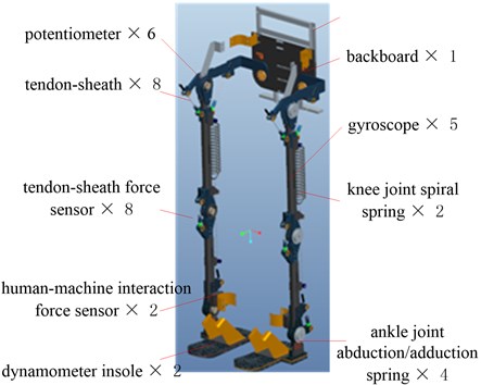
Setting heavy drives such as hydraulic cylinders and motors at exoskeleton’s joints would lead to huge inertia of the mechanical legs, thereby reduce the motion control precision of the drives and increase the required power. Thus, each joint of the exoskeleton mentioned in this paper is driven through the tendon sheath by the integrated hydraulic cylinders placed on the exoskeleton’s backboard which executes a small range of movement during normal walking [15].
The original design of the exoskeleton is shown in Fig. 1 and each joint is in single-axis type.
Fig. 1Original design of the exoskeleton
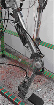
As shown in Fig. 2(a), potentiometers in each joint are to detect the exoskeleton’s posture.
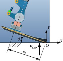
As shown in Fig. 2(b), dynamometer insoles are to detect the ground reaction forces, based on this detection, the human’s stance leg movement intention could be judged and the ground reaction torques acting on the exoskeleton’s ankle joints could be obtained (Fig. 3 and Eq. (1)) to calculate the desired torques of the hip, knee and ankle joints of the exoskeleton’s stance leg.
As shown in Fig. 2(c), human-machine interaction force sensors set at each ankle joint are to detect the human’s swing leg movement intention.
As shown in Fig. 2(d), gyroscopes set at each segment of the exoskeleton are to detect the angles between each segment and the gravity in sagittal plane.
Fig. 2Sensors on the exoskeleton
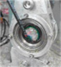
a) Potentiometer
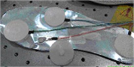
b) Dynamometer insole
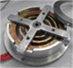
c) Human-machine interaction force sensor
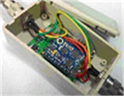
d) Gyroscope
Fig. 3Ground reaction torque acting on exoskeleton’s ankle joint
According to the arrangement of sensors, the exoskeleton only needs to be banded with human’s body at waist and ankle joint.
3. Human-machine coordination experiments
As shown in Fig. 4(a), the human-machine coordination experiments were conducted to testify the rationality of the exoskeleton structure as shown in Fig. 1. In the experiments, we firstly adjusted the lengths of the exoskeleton’s thigh and shank to suit the volunteers’ stature (seven health young males, 25±2 years old, 1.75±0.02 m) in upright posture, then the volunteers worn the exoskeleton with no driving and walked on the treadmill in normal gait, the PC synchronously collected the exoskeleton’s joint angles (Fig. 2(a)) and the human-machine interaction force at ankle joint (Fig. 2(c)). After each volunteer accomplished the experiment thrice, mean values of each set of data were calculated. In the results, we observed that violent chattering (the unnormal, reciprocating and rapid rotation within the scope of small-angle) occurred at the exoskeleton’s hip and knee joints in early swing phase (Fig. 4(b)), furthermore, the volunteers represented that obvious and uncomfortable pull-feeling (interaction force) exist between their ankle joints and the exoskeleton’s (Fig. 4(c)).
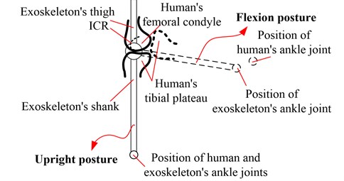
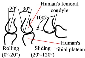
Chattering would harm the control of drive system, and pull-feeling would go against the detection of human movement intention. Kinematics difference between the exoskeleton’s single-axis knee joint and human’s complex trochlea knee joint (Fig. 5) was considered to be the primary cause of these issues, because the human-machine relative locations of hip and ankle joints maintained fixed.
Knee is the biggest and most complex joint in human body. As shown in Fig. 5, during walking, relative movement between femoral condyle and tibial plateau is the combination of anterior-posterior (AP) sliding and flexion-extension (FE) rotation. M. Boujelbene et al. analyzed the biomechanical characteristics and biotribological behavior in the AP sliding and FE rotation respectively by using the knee prothesis simulator [16]; in reference [17], V. A. D. Cai et al. measured the knee joint kinematics using an active 6 DoF electro-goniometer called self-adjusting isostatic exoskeleton [18], and obtained the knee joint instantaneous helical axis for flexion movement; K. M. Lee et al. investigated the human’s knee joint kinematics via comparing three mathematically approximative models and obtained the effect of rolling-sliding ratio to the knee joint kinematics [19]. When the knee joint flexes, the ICR (instantaneous center of rotation between femoral and tibial) trajectory in sagittal plane forms a “J” shape, which causes the change of curvature radius of the tibial plateau’s rotation around the femoral condyle to be even more than 40 mm [20]. Therefore, the human ankle joint trajectory is inevitably different from that of the exoskeleton with single-axis knee joints.
Fig. 4Human-machine coordination experiment
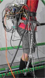
a) Scene of the human-machine coordination experiments
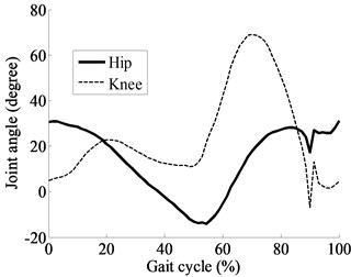
b) Chattering at the exoskeleton’s hip and knee joints
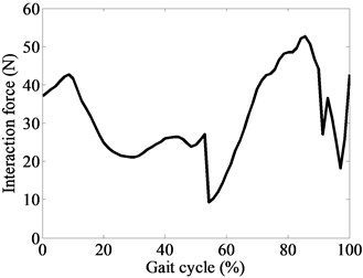
c) Pull-feeling between human’s ankle joints and exoskeleton’s
Fig. 5Kinematics difference between exoskeleton’s knee joint and human’s
4. Analysis of human-machine coordination experiment results
To verify the analysis in Section 2, we carried out the human gait experiments and the kinematics and inverse kinematics analysis of the exoskeleton, and then compared the results of them.
4.1. Human gait experiments
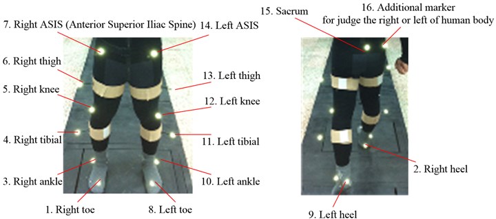
In order to make the human gait experiment results be suitable to 90 % Chinese adults, 7 healthy young male volunteers (25±2 years old, 62.5±7.5 kg, and 1.75±0.02 m) were invited according to the Chinese National Standard GB10000-1988, as shown in Fig. 6. The position of each marker on volunteer’s body as shown in Fig. 7 and the empirical formulas used in calculation are of the reference [21]. Every volunteer accomplished the gait experiment twice, and then we got the mean values of each set of the experimental data. The detailed algorithm for image acquisition and calculation of each marker’s coordinate in XYZ is of the reference [14].
Fig. 6Human gait experiment
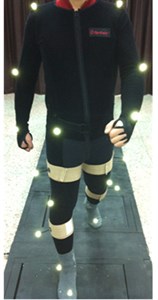
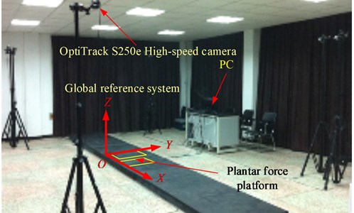
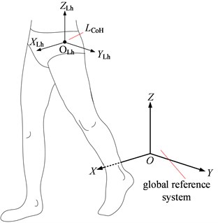
Fig. 7Maker on volunteer’s body and the local reference system at the centre of human’s left hip joint
a)
b)
On the human’s left leg, for example, local reference systems (uvw) are set on marker 15, 12 and 10 respectively, as shown in Fig. 8 and Eqs. (2-4).
In Eqs. (2-4), pi is the coordinate of the maker i in XYZ.
The positions of centres of joint of human’s left leg in XYZ could be obtained by Eqs. (5-7).
Annotations of the constants in Eqs. (5-7) are listed in Table 1.
Fig. 8Local reference systems on human’s left leg
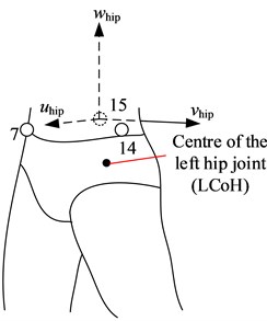
a) Hip
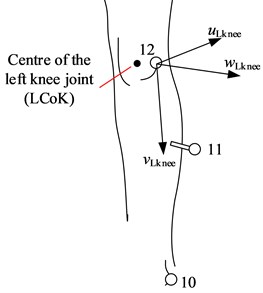
b) Knee
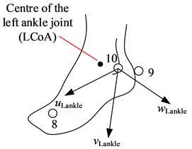
c) Ankle
Table 1Annotations of the symbols
C1 | Breadth of ASIS |
C2 | Diameter of the left knee |
C3 | Length of the left foot |
C4 | Height of the left malleolus |
C5 | Width of the left malleolus |
Reference system XLhYLhZLh is set at the centre of human’s left hip joint, as shown in Fig. 7, and the coordinate axes are respectively parallel to those of XYZ. Then, the position of each joint centre of the left leg in XYZ could be converted to be in XLhYLhZLh, as Eq. (8).
By Eq. (5-8), we could obtain the human ankle joint trajectory relative to hip joint in sagittal plane in normal gait (Fig. 9(a)) and the length changes of human’s thigh and shank (Fig. 9(b)). The length changes of human’s thigh and shank reflect the human knee joint charateristics of trochlea, and also influence the human’s ankle joint trajectory.
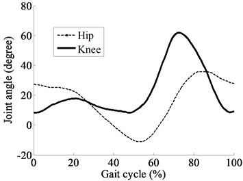
After getting the positions of joint centres, we could obtain the coordinates of segment centres of mass of human’s lower extremity in XYZ, and then obtain the joint angles.
To calculate the left knee angle, for example, local reference systems (xyz) are set at the centres of mass of human’s left thigh and left shank, as shown in Fig. 10 and Eq. (9-10).
The positions of centres of mass of human’s left thigh and left shank in XYZ were calculated by Eq. (11-12).
The human’s left knee angle in sagittal plane could be calculated by Eq. (13-14).
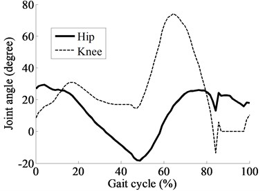
According to the above algorithm, the curves of human’s hip and knee angles in sagittal plane in a normal gait were obtained as shown in Fig. 11.
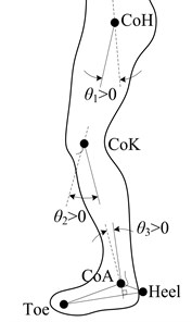
The direction definition of joints of human’s lower extremity in sagittal plane is shown in Fig. 12.
Fig. 9Part of the results of the human gait experiments
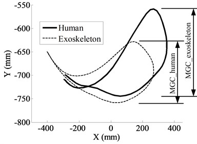
a) Ankle joint motion trajectory
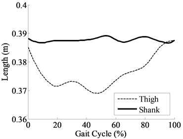
b) Lengths of human’s thigh and shank
Fig. 10Local reference systems at segment centres of mass of human’s left leg
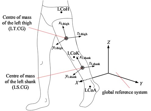
Fig. 11Human’s hip and knee joint angles
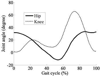
Fig. 12Direction definition
zLthigh=xLthigh×yLthigh,
zLshank=xLshank×yLshank,
4.2. Kinematics analysis of the exoskeleton
As shown in Fig. 13, a kinematic model of the exoskeleton in the sagittal plane was established and the reference system XHY is set at the hip joint.
The coordinate of exoskeleton’s ankle joint A in XHY ((XAYA)T) could be calculated by Eq. (15). The lengths of exoskeleton’s thigh and shank are equal to the mean values of the lengths of the volunteers’ thighs and shanks in the upright posture respectively.
Fig. 13Kinematic model of the exoskeleton with single-axis knee joint
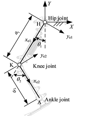
Make the exoskeleton walk in terms of the human’s hip and knee joint angles (Fig. 11), the ankle joint trajectory in XHY in a gait could be obtained by Eq. (15), as shown in Fig. 9(a). It could be found that the maximum ground clearance (MGC) of human’s ankle joint in a normal gait is significantly greater than that of exoskeleton with single-axis knee joint, which is one of the kinematics advantages of human’s rolling-sliding trochlea knee joint. Obvious human-machine ankle joint movement error was observed, thus the pull-feeling represented by volunteers in the human-machine coordination experiments could be explained.
4.3. Inverse kinematics analysis of the exoskeleton
Because the exoskeleton mentioned in this paper only need to be banded with human’s body at waist and ankle, the human-machine ankle joint motion error should be as small as possible during walking.
Therefore, in the inverse kinematics analysis of the exoskeleton, the human’s ankle joint motion trajectory as shown in Fig. 9(a) is set to be the target trajectory of the exoskeleton’s ankle joint. The process of inverse kinematics analysis is as follows.
The point on the human ankle joint motion trajectory (AB)T was set to be the desired position of the exoskeleton’s ankle joint in XHY, as Eq. (16). (θ'1θ'2)T was the exoskeleton’s hip and knee joint angles corresponding to (AB)T.
The θ'2 could be calculated as Eq. (20):
By Eq. (16) and Eq. (20), we could obtain the Eq. (21):
k1=-a1-a2cosθ'2<0,k1=a2sinθ'2>0.
The variables r and γ were set as Eq. (22):
By the Eq. (21), we could obtain the Eq. (23) and Eq. (24):
The θ'1 could be calculated as Eq. (25):
The values of θ'1 and θ'2 must be corrected into the range (–π/2, π/2) and (0, π/2) respectively.
As the results, the exoskeleton’s hip and knee joint angles are shown in Fig. 14, and the abrupt angle changes indicated that the chattering of exoskeleton’s hip and knee joint observed in the human-machine coordination experiments was inevitable when exoskeleton has the nearly same ankle joint trajectory as human’s.
5. Structure optimization of exoskeleton’s knee joint
Chattering and pull-feeling were the synthetically results of the kinematics and inverse kinematics analyses of the exoskeleton, hence the kinematics limitation of the exoskeleton’s single-axis knee joint could be confirmed to be the primary cause of these issues. Therefore, it is necessary to optimize the exoskeleton’s knee joint.
Fig. 14Exoskeleton’s hip and knee joint angles
Differ from the predecessors’ valuable achievements of adopting cam mechanisms [9] or multi-bar linkages [10, 11] to precisely fit the ICR trajectory of human’s knee joint, our goal of optimizing the exoskeleton’s knee joint in four-bar linkage type is to minimize the human-machine ankle joint motion error when the exoskeleton walks in human’s normal gait.
Fig. 15Kinematic model of the exoskeleton with four-bar linkage knee joint
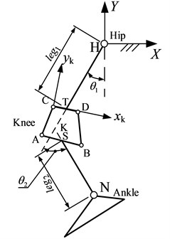
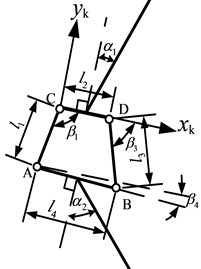
Kinematic model of the exoskeleton with four-bar linkage knee joint in the sagittal plane is shown in Fig. 15. The base reference system XHY is set at the hip joint. The local reference system xkCyk is set at the hinge C of the four-bar linkage, and the axis xk is coincident with the bar CD. Thus, there are 10 parameters needed to be optimized as listed in Table 2.
Table 2The parameters needed to be optimized
l1 | Lengths of bars of the four-bar linkage | leg2 | Length of the exoskeleton’s shank |
l2 | α1 | Installation angle between the four-bar linkage and the exoskeleton’s thigh | |
l3 | α2 | Installation angle between the four-bar linkage and the exoskeleton’s shank | |
l4 | s1 | s1=(xkT-xkC)/(xkD-xkC) | |
leg1 | Length of the exoskeleton’s thigh | s2 | s2=(xkS-xkA)/(xkB-xkA) |
As shown in Fig. 15, we make the extensions of the thigh leg1 and shank leg2 intersect at the point K, so the angles of the exoskeleton’s hip and knee joints could be respectively expressed as θ1 and θ2, and the values of them in the process of optimization are set to be equal to human’s as shown in Fig. 11.
The optimization process is as below:
With regard to the four-bar linkage, there is the geometrical relationship as Eq. (27):
The expressions of Ri (i = 1, 2, 3) are as below:
The value of β3 could be obtained by Eq. (28):
Positions of the point A, B, C and D of the four-bar linkage in xkCyk are calculated by Eq. (29-32).
Position of the ankle joint N in xkCyk and XHY could be obtained by Eq. (33) and Eq. (34) respectively.
As Eq. (35), the optimization objective is to minimize the variance of human-machine ankle joint motion error in a gait.
where n is the number of frames of the data collected in a gait in the human gait experiments as shown in Fig. 6.
The constraint conditions are as below:
1. As shown in Table 3, the value ranges of each parameter are set to ensure the practicability of the knee joint and the convenience of assembling.
2. The four-bar linkage knee joint should be a double-rocker mechanism, therefore, l4 is set to be the longest bar while l2 to be the shortest one, meanwhile, the four-bar linkage could not satisfy the condition of the sum of bar lengths, as Eq. (36).
Table 3Value ranges of each parameter
Parameter | l1 | l2 | l3 | l4 | leg1 | leg2 | α1 | α2 | s1 | s2 |
Unit | mm | rad | non-dimensional | |||||||
Range of value | 50-150 | 300-400 | –π/2-π/2 | –1/2-1 | 0-1 | |||||
3. In order to make the structure of the exoskeleton be similar to human body as far as possible, as shown in Fig. 15, the point T should not be behind the point S in the horizontal direction when the exoskeleton is at upright posture (θ1=0, θ2=0), and the horizontal distance of them should be less than 35 mm, as Eq. (37-39) which are obtained by Eq. (34).
Matlab was used to accomplish the optimization calculation, and the results are listed in the Table 4.
Table 4Optimized values of each parameter
Parameter | l1 | l2 | l3 | l4 | leg1 | leg2 | α1 | α2 | s1 | s2 |
Unit | mm | rad | non-dimensional | |||||||
Value (rounding) | 67 | 57 | 57 | 120 | 345 | 350 | 0 | 0.012 | –0.13 | 0.59 |
6. Verification of the optimal result
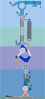
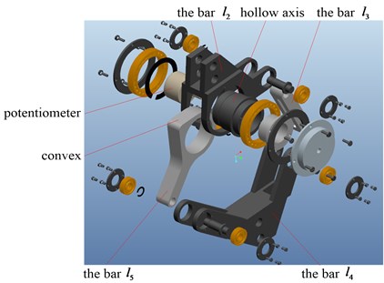
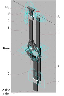
For verifying the rationality of the optimization results, a virtual prototype of the exoskeleton with optimized knee joint was established in Pro/E as shown in Fig. 16(a), the convex marked in Fig. 16(b) was designed for preventing the dangerous contrarotation of the knee joint. Kinematics simulation of the virtual prototype was conducted in Adams as shown in Fig. 16(c).
The virtual prototype in Adams (Fig. 16(c)) only shows the constraint relationship between the components. Bar 1 and bar 2 are thigh and shank of the exoskeleton respectively; bar 3 and bar 4 connected with each other by hinge joint, and are parallel to bar 1 and bar 2 respectively. Bar 4 is fixed to bar 2 via component 6; component 5 could slide up and down along bar 1; head face A of bar 3 and head face B of bar 5 remain in the same plane. Hence, the angle between bar 3 and bar 4 is equal to the angle between bar 1 and bar 2 which is the knee joint angle of the exoskeleton. Therefore, we could set a “Rotational Joint Motion” on the hinge joint between bar 3 and bar 4 to achieve for the definition and measurement of the exoskeleton’s knee joint angle. For defining and measuring the exoskeleton’s ankle joint trajectory, we could set a “General Point Motion” on the “MARKER” named “Ankle point” in Fig. 16(c), and the “Ankle point” is also the centre of the bottom surface of bar 2.
Two kinds of kinematics simulation of the virtual prototype were carried out as follows:
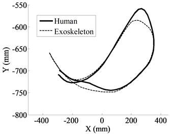
1. The exoskeleton’s hip and knee joint angles were set to be equal to human’s as shown in Fig. 11, and the human-machine ankle joint movement error (which primarily led to the pull-feeling) was shown in Fig. 17(a). Compared Fig. 17(a) with Fig. 9(a), obvious improvement in the human-machine ankle joint trajectory error could be observed.
2. The human ankle joint trajectory (Fig. 9(a) or Fig. 17(a)) was set to be the reference trajectory of the exoskeleton, and the exoskeleton’s hip and knee joint angle curves were obtained as shown in Fig. 17(b). Compared Fig. 17(b) with Fig. 14, abrupt angle changes of the exoskeleton’s hip and knee joints (which were reflected as the chattering) have been eliminated.
Fig. 16Verification of the optimal result
a) Optimized exoskeleton in Pro/E
b) Exploded view of the optimized knee joint
c) Virtual prototype in Adams
Fig. 17Simulation results
a) According to human’s hip and knee joint angles
b) According to human ankle joint motion trajectory
7. Conclusions
Swing leg and stance leg of the exoskeleton mentioned in this paper are controlled according to signals of the ankle joint human-machine reaction force sensors and the dynamometer insoles respectively. On the foundation of this control strategy, the exoskeleton only needs to be banded with human’s body at waist and ankle joint. Hence, on the premise of smooth of the exoskeleton’s joint angle curves in normal gait, the human-machine ankle joint motion coordination should be ensured.
Human-machine coordination experiments were carried out to testify the structure rationality of the exoskeleton whose knee joint was in single-axis type. In the experiments, violent chattering of exoskeleton’s hip and knee joint was observed in early swing phase, and significant pull-feeling at ankle joint was presented by the volunteers. Joint chattering was harmful to the control of drive system, and ankle joint pull-feeling went against the comfort of wearing and the accuracy of the detection of human movement intention.
For solving the above issues, firstly, human gait experiments were conducted to obtain the human gait data. Then, in regard to the exoskeleton, kinematics analysis based on the human’s hip and knee joint angles indicated the obvious human-machine ankle joint movement error; inverse kinematics analysis according to the human ankle joint trajectory reflected the abrupt angle changes of exoskeleton’s hip and knee joints.
Chattering and pull-feeling were the synthesization of the kinematics and inverse kinematics analysis results, thus, the kinematics difference between the exoskeleton’s single-axis knee joint and human’s trochlea knee joint was regarded as the primary cause of these issues.
Four-bar linkage was adopted to optimize the exoskeleton’s knee joint, and the aim of optimization was to minimize the human-machine ankle joint movement error when the exoskeleton walks in terms of the human’s hip and knee joint angles.
Kinematics simulation of the virtual prototype of the optimized exoskeleton was accomplished, and the results showed that in normal gait, both of the human-machine ankle joint movement error and the abrupt angle changes of exoskeleton’s hip and knee joints have been significantly reduced. Therefore, effectiveness of the exoskeleton’s knee joint optimization for improving the human-machine coordination could be confirmed.
References
-
Zoss A. B., Kazerooni H., Chu A. Biomechanical design of the Berkeley Lower Extremity Exoskeleton (BLEEX). IEEE/ASME Transactions on Mechatronics, Vol. 11, Issue 2, 2006, p. 128-138.
-
Pratt J. E., Kurpp B. T., Morse C. J., et al. The RoboKnee: an exoskeleton for enhancing strength and endurance during walking. Proceedings of the IEEE International Conference on Robotics & Automation, New Orleans, United States, 2004, p. 2430-2435.
-
Sakurai T., Sankai Y. Development of motion instruction system with interactive robot suit HAL. Proceedings of the 2009 IEEE International Conference on Robotics and Biomimetics, Guilin, China, 2009, p. 1141-1147.
-
Freudenstein F., Woo L. S. Kinematics of the human knee joint. The Bulletin of Mathematical Biophysics, Vol. 31, Issue 2, 1969, p. 215-232.
-
Ling Z. K., Guo H. Q., Boersma S. Analytical study on the kinematic and dynamic behaviors of a knee joint. Medical Engineering & Physics, Vol. 19, Issue 1, 1997, p. 29-36.
-
Koo S., Andriacchi T. P. The knee joint center of rotation is predominantly on the lateral side during normal walking. Journal of Biomechanics, Vol. 41, Issue 6, 2008, p. 1269-1273.
-
Castelli V. P., Leardini A., Gregorio R. D., et al. On the modeling of passive motion of the human knee joint by means of equivalent planar and spatial parallel mechanisms. Autonomous Robots, Vol. 16, Issue 2, 2004, p. 219-232.
-
Hamon A., Aoustin Y., Caro S. Two walking gaits for a planar bipedal robot equipped with a four-bar mechanism for the knee joint. Multibody System Dynamics, Vol. 31, Issue 3, 2014, p. 283-307.
-
Wang D. H., Guo J. J., Lee K. M., et al. An adaptive knee joint exoskeleton based on biological geometries. Proceedings of the IEEE International Conference on Robotics and Automation, Shanghai, China, 2011, p. 1386-1391.
-
Kim K. J., Kang M. S., Choi Y. S., et al. Development of the exoskeleton knee rehabilitation robot using the linear actuator. International Journal of Precision Engineering and Manufacturing, Vol. 13, Issue 10, 2012, p. 1889-1895.
-
Xie H. L., Liang Z. Z., Li F., et al. The knee joint design and control of above-knee intelligent bionic leg based on magneto-rheological damper. International Journal of Automation and Computing, Vol. 7, Issue 3, 2010, p. 277-282.
-
Bertomeu J. M. B., Lois J. M. B., Guillem R. B., et al. Development of a hinge compatible with the kinematics of the knee joint. Prosthetics and Orthotics International, Vol. 31, Issue 4, 2007, p. 371-383.
-
Han Y. L., Wang X. S. The biomechanical study of lower limb during human walking. Science : Technological Sciences, Vol. 54, Issue 4, 2011, p. 983-991.
-
Han Y. L., Wang X. S., Fu C. Q., et al. The study on human walking gait analysis system for the design of walking power-assisted robot. Proceedings of the IEEE International Conference on Mechatronics and Automation, Changchun, China, 2009, p. 3607-3612.
-
Jia S., Han Y. L., Niu W. Q., et al. Mechanical design and improvement of the lower extremity joints of the SEU Power-Assistant Exoskeleton (SPAEX). Proceedings of Mecatronics, Yokohama, Japan, 2010, p. 480-485.
-
Boujelbene M., Dhouibi S., Kharrat M., et al. Analysis of the biotribological behavior for the stainless steel_polyethylene contact using a knee prosthesis simulator. Journal of Bionic Engineering, Vol. 9, Issue 1, 2012, p. 59-65.
-
Cai V. A. D., Bidaud P., Hayward V., et al. Kinematic measurement of the knee joint using self-adjusting isostatic exoskeleton. Journal of Biomechanics, Vol. 45, Issue S1, 2012, p. S517.
-
Cai V. A. D., Bidaud P., Hayward V. Self-adjusting, isostatic exoskeleton for the human knee joint. Proceedings of the 33rd Annual International Conference of the IEEE EMBS, USA, 2011, p. 612-618.
-
Lee K. M., Guo J. J. Kinematic and dynamic analysis of an anatomically based knee joint. Journal of Biomechanics, Vol. 43, Issue 7, 2010, p. 1231-1236.
-
Gao S. L. Atlas of Practical Anatomy. Second Edition, Science and Technology Press, , , 2004, p. 214-216.
-
Vaughan L., Davis B. L., O’Connor J. C. Dynamics of Human Gait. Second Edition, Kiboho Publishers, Cape Town, South Africa, 1999, p. 16-20.
About this article
This work is supported by National Nature Science Foundation of China (51205182), Nature Science Foundation of Jiangsu Province (BK2012474), and Graduate Student Research Innovation Foundation of Jiangsu Province (CX10B-063Z, CXZZ_0140).
