Abstract
The gears in the high-speed heavy-duty gearbox of the high-speed train are typical high-speed heavy-duty gears. Combined with the transmission principle and structural characteristics of the high-speed train drive gearbox, to ensure adequate lubrication of meshing gears and bearings, an optimization of the lubricating oil flow inside the gearbox was conducted. The oil and gas two-phase flow model inside the gearbox adopts the VOF model, and the turbulence model adopts the standard κ-ε model. Fluent is used for simulation calculation. The results show that the exhaust port position of the gearbox has little effect on the flow of lubricating oil inside the gearbox; the overall pressure distribution inside the gearbox is relatively uniform, with higher pressure only at the meshing gears; the distribution of lubricating oil inside the gearbox is related to the rotation of the gears, and the flow velocity of lubricating oil is mainly affected by the rotation of the gears, with the maximum flow velocity appearing around the gears; the flow of lubricating oil inside the gearbox meets the lubrication requirements of the gearbox. These results provide support for the lubrication design, flow channel structure improvement, and effectiveness evaluation of high-speed train transmission gearboxes.
1. Introduction
The high-speed train drive gearbox is installed on the bogie of the high-speed train car body, suspended at the front end of the car body and bogie. The drive motor is connected to the gearbox on the bogie to transmit power and propel the high-speed train. As shown in Fig. 1, the high-speed train drive gearbox is responsible for traction and speed control of the train. It is a typical single-stage high-speed heavy-duty gear transmission, usually consisting of a pair of meshing gears, bearings, and a lubrication system to ensure smooth operation of the gearbox [1].
Fig. 1High-speed train drive gearbox
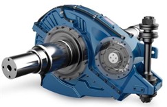
High-speed train drive gear box gear box body internal by a pair of external meshing gears through the large gear oil churning formation of immersion and splash lubrication, splash lubricant and realize the lubrication of bearings [2]. The lubricating oil eventually flows back to the bottom of the casing to complete the circulation within the gearbox. Adequate lubrication of gears and bearings is crucial for ensuring safe operation of the high-speed train. Poor bearing lubrication can lead to temperature rise, vibration, and abnormal noise, while poor gear lubrication can cause surface adhesion and wear [3]-[5].
To prevent oil leakage from the exhaust vents during operation of the high-speed train drive gearbox, it is necessary to analyze the pressure distribution inside the gearbox and the flow of lubricating oil, and to assess the impact of exhaust vent positions on lubricating oil flow [6].
This paper analyzes the flow of lubricating oil inside a certain model of high-speed train drive gearbox using Fluent, obtaining the velocity and pressure distribution of lubricating oil inside the gearbox. This analysis provides technical support for lubrication design, flow channel structure improvement, and performance evaluation of high-speed train transmission gearboxes [7].
2. Model and grid division
The volume fraction of oil and gas two-phase flow inside the gearbox changes at the interface, causing motion and deformation at the interface. Therefore, the VOF model [8] is used to describe the interface between the two fluids. The turbulence model adopts the standard κ-ε model [9] for moderate computational complexity and high accuracy. Additionally, considering the effects of forces between gas-liquid phases, surface tension, and gravity, the Simple algorithm [10] is employed. This approach can handle complex geometries and boundary conditions, using any type of grid, while solving other equations such as energy and turbulence with first-order implicit methods. The standard wall function [11] is used near the walls, requiring less computation and suitable when wall proximity has minimal impact on overall flow.
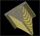
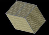
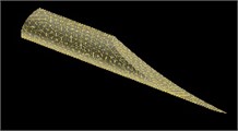
Due to the complex structure of the gearbox, unstructured hexahedral grids are used in three-dimensional numerical simulations to ensure accuracy and reduce computational time. The gearbox computational domain is divided using block-structured grid partitioning techniques into five major blocks: front gearbox, middle gearbox, rear gearbox, small gear region, and large gear region, each further subdivided into multiple blocks, totaling approximately 5 million grid cells as shown in Fig. 2.
Fig. 2Gearbox grid division

a) Front of gearbox
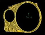
b) Gear box middle part

c) Rear of gearbox

d) Pinion gear area
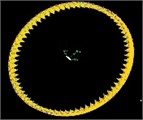
e) Large gear area
f) Block grid in large gear area
g) Local grid of tubing
h) Local grid of exhaust holes
3. Influence of exhaust port positions on lubricating oil flow
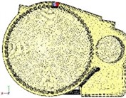
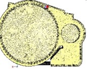
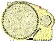
Fig. 3 shows the CFD computational model of the gearbox [12], with red markers indicating the positions of exhaust ports in the gearbox. Three different exhaust port positions were selected for calculation: one at the original position (Prototypical case 1), and two others positioned to the right of the original exhaust port location (Modified case 2 and Modified case 3).
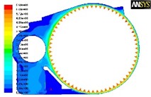
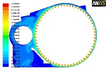
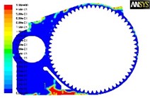
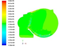
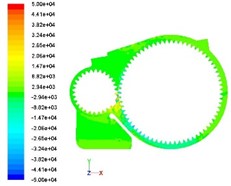
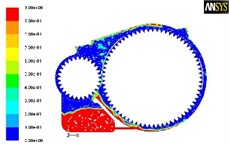
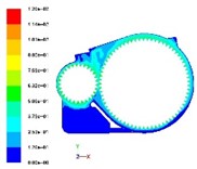
During calculation, with oil level h=34 mm and rotational speed ω=200 rad/s, the effects of different exhaust port positions on the flow field inside the gearbox were analyzed under stable lubricating oil flow conditions over a calculation period of 0.24 s. The results at time t=0.15 s are shown in Figs. 4-5, depicting velocity distribution and volume fraction of oil at the same cross-section taken at the axial center of the gearbox, reflecting velocity and lubricating oil distribution within the gearbox.
From Fig. 4 and 5, the velocity distribution and the volume fraction of the lubricant in the gearbox changed slightly after the case 2 and case 3 modifications compared to the case 1 prototype.
Based on the CFD simulation results, Fig. 6 shows the variation in large gear power loss over time due to different exhaust port positions, as well as the corresponding average power loss values. Although the power loss of the large gear varies over time with different positions, the fluctuation frequency is generally consistent, with fluctuation ranges within 1-2 kW, which is within the acceptable range. Comparing the average power loss values of the modified cases with Prototypical case 1, Modified case 2 shows a reduction of 0.064 kW (a relative decrease of 4.9 %), while Modified case 3 shows an increase of 0.073 kW (a relative increase of 5.7 %). Therefore, the impact of the modified exhaust port positions on power loss is minimal compared to the original position.
In conclusion, based on comprehensive CFD simulation results, the influence of exhaust port positions on the flow field inside the gearbox is not significant.
Fig. 3CFD computational model of the gearbox
c) Prototypical case 1
b) Modified case 2
c) Modified case 3
Fig. 4Velocity distribution at different vent positions
a) Prototypical case 1
b) Modified case 2
c) Modified case 3
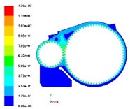
Fig. 5Volume fraction of lubricating oil at different exhaust port positions
a) Prototypical case 1
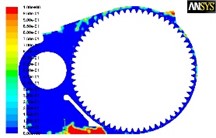
b) Modified case 2
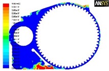
c) Modified case 3
4. Overall pressure distribution inside the gearbox
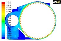
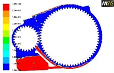
Under the condition where two gears are rotating simultaneously, five surfaces perpendicular to the gear axis are taken as characteristic sections for analysis, as shown in Fig. 7. Sections 1 and 5 display the static pressure distribution in the non-gear regions inside the gearbox, while Sections 2 and 3, and 4 show the static pressure distribution at the gear meshing locations. Fig. 8 presents a contour map of the static pressure distribution inside the gearbox.
From Fig. 8, it can be observed that the overall pressure distribution inside the gearbox is relatively uniform, with pressure increasing only at the gear meshing points.
Fig. 6Variation in power loss of the large gear with different exhaust port positions over time and corresponding average power loss values
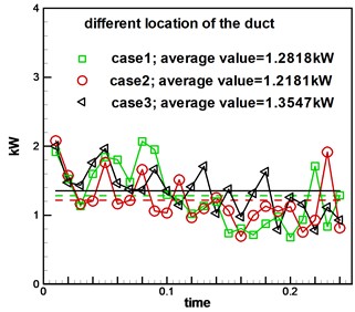
Fig. 7Schematic diagram of section position
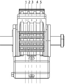
Fig. 8Static pressure distribution at different sections inside the gearbox
a) Section 1
b) Section 2
5. Simulation results and analysis of lubricating oil flow
To reduce computational complexity, based on the gearbox structure, a two-dimensional simplification of the lubricating oil flow at the gear meshing locations was conducted, with a dynamic simulation along the axial middle section [13]-[14].
The simulation of gear meshing motion adopts a two-dimensional dynamic mesh. Due to the small clearances between gears, to ensure calculation accuracy, a small mesh scale with a total of 501,672 meshes was used. Gear rotation was driven by a dynamic UDF (User Defined Function), enabling transient meshing flow simulation of the two-dimensional gears.
Lubricating oil flow distribution inside the gearbox is shown in Fig. 9. The figure takes a section at the axial center position of the gearbox to show the gear meshing situation.
In the calculations, the large gear rotates clockwise; blue represents gas phase and red represents liquid phase.
From Fig. 9, it can be observed that the distribution of lubricating oil inside the gearbox is related to the rotation of the gears [15]. The lubricating oil lifted by the large gear is then pushed to the gear contact area by the small gear, and finally thrown to the top of the gearbox.
Since the velocity field inside the gearbox is mainly influenced by the rotation of the gears, sections at the gear meshing points were taken, such as sections 2, 3, and 4 from Fig. 7. Sections 2 and 3 are close to each other, with similar velocity distributions; thus sections 2 and 4 were selected, as shown in Fig. 10. It can be seen from Fig. 10 that the maximum velocity inside the gearbox appears around the gears. There are differences in velocity distribution among different sections, but overall the differences are not significant.
From the analysis, it is evident that the flow of lubricating oil inside the gearbox ensures sufficient lubrication at the gear meshing points, and the lubricating oil thrown to the top of the gearbox also provides lubrication to the bearings, meeting the lubrication requirements of the gearbox.
Fig. 9Distribution of lubricating oil in gearbox at different times
a) Two volume fraction nephograms at 0.047032 seconds
b) Two volume fraction nephograms at 0.065908 seconds
Fig. 10Distribution of velocity field inside the gearbox
a) Section 2
b) Section 4
6. Conclusions
This paper analyzes the flow of lubricating oil inside the gearbox during the operation of high-speed train transmission gearboxes. The two-phase flow model (oil and gas) inside the gearbox adopts the VOF model, and the turbulence model uses the standard κ-ε model with the Simple algorithm. Simulation calculations were performed using Fluent software, and the results show: (1) The position of the exhaust port of the gearbox has a slight influence on the velocity field inside the gearbox, the volume fraction of lubricating oil, and the power loss of the large gear, but the impact is not significant, indicating that the position of the exhaust port has little effect on the flow of lubricating oil inside the gearbox; (2) The overall pressure distribution inside the gearbox is relatively uniform, with higher pressure only at the gear meshing points; (3) The distribution of lubricating oil inside the gearbox is related to the rotation of the gears. The velocity field is mainly influenced by the rotation of the gears, and the maximum flow velocity appears around the gears. There are differences in velocity distribution along the axial sections inside the gearbox, but overall the differences are not significant. The flow of lubricating oil inside the gearbox meets the lubrication requirements of the gearbox.
Through the simulation analysis of professional fluid simulation software, it is concluded that the position of the exhaust port has little influence on the flow of lubricating oil, the highest pressure is at the gear mesh, and the maximum flow rate in the box is around the gear, which provides technical support for the lubrication design, channel structure improvement and performance evaluation of high-speed train transmission gear box.
References
-
Z. Y. Li, “Manufacturing process and quality control of gearbox body of CRH380B high-speed railway,” Modern Industrial Economy and Informatization, Vol. 11, No. 4, pp. 33–34, 2021, https://doi.org/10.16525/j.cnki.14-1362/n.2021.04.14
-
C. C. Feng, Q. B. Dong, and J. Wei, “Simulation analysis of internal flow field and calculation of oil churning loss in high-speed locomotive gearboxes,” Lubrication and Sealing, Vol. 47, No. 1, pp. 101–110, 2022.
-
M. Singh Raghav and S. Patel, “Crack propagation and fatigue life estimation of spur gear with and without spalling failure,” Theoretical and Applied Fracture Mechanics, Vol. 127, p. 104020, Oct. 2023, https://doi.org/10.1016/j.tafmec.2023.104020
-
C. Peeters, W. Wang, D. Blunt, T. Verstraeten, and J. Helsen, “Fatigue crack detection in planetary gears: Insights from the HUMS2023 data challenge,” Mechanical Systems and Signal Processing, Vol. 212, p. 111292, Apr. 2024, https://doi.org/10.1016/j.ymssp.2024.111292
-
T. Ji, S. Huang, B. Ren, J. Ye, and G. Wang, “Analysis of grinding fluid flow in high-temperature alloy surface profile grinding,” The International Journal of Advanced Manufacturing Technology, Vol. 124, No. 3-4, pp. 759–771, Jun. 2022, https://doi.org/10.1007/s00170-022-09448-x
-
S. Ullah, Z. Ahmad, and J.-M. Kim, “Fault diagnosis of a multistage centrifugal pump using explanatory ratio linear discriminant analysis,” Sensors, Vol. 24, No. 6, p. 1830, Mar. 2024, https://doi.org/10.3390/s24061830
-
B. Zhu, “Influence of high-speed rail gearbox cavity structure on lubrication performance of gears and bearings,” Zhongyuan University of Technology, No. 3, 2023, https://doi.org/10.27774/d.cnki.gzygx.2023.000135
-
D. Q. Zhou et al., “Proposed two-phase flow in an inlet shaft of a deep tunnel system based on the VOF model,” China Water Supply and Drainage, Vol. 39, No. 19, pp. 132–138, 2023, https://doi.org/10.19853/j.zgjsps.1000-4602.2023.19.019
-
N. Reeh, G. Manthei, and P. J. Klar, “Soft sensor technology for the determination of mechanical seal friction power performance,” Applied System Innovation, Vol. 7, No. 3, p. 39, May 2024, https://doi.org/10.3390/asi7030039
-
F. Falcao, E. A. Vargas, R. Velloso, and A. C. Soares, “Hydromechanical simulation of a carbonate petroleum reservoir using pseudo-coupling,” Geoenergy Science and Engineering, Vol. 237, p. 212769, Jun. 2024, https://doi.org/10.1016/j.geoen.2024.212769
-
E. Rondeaux, A. Poubeau, C. Angelberger, M. Munoz Zuniga, D. Aubagnac-Karkar, and R. Paoli, “Exploring the potential and the practical usability of a machine learning approach for improving wall friction predictions of RANS wall functions in non-equilibrium turbulent flows,” Flow, Turbulence and Combustion, Vol. 112, No. 4, pp. 975–1000, Mar. 2024, https://doi.org/10.1007/s10494-024-00539-1
-
G. Muzzioli, G. Paini, F. Denti, F. Paltrinieri, L. Montorsi, and M. Milani, “A lumped parameter and CFD combined approach for the lubrication analysis of a helical gear transmission,” in Journal of Physics: Conference Series, Vol. 2385, No. 1, p. 012034, Dec. 2022, https://doi.org/10.1088/1742-6596/2385/1/012034
-
Q. Zeng et al., “Two-dimensional evolution of temperature and deformation fields during dynamic shear banding: In-situ experiments and modeling,” International Journal of Plasticity, Vol. 171, p. 103782, Dec. 2023, https://doi.org/10.1016/j.ijplas.2023.103782
-
M. A. Rahman, J. I. Shu, Y. Qian, Y. Wang, and J. A. Khan, “Multi-phase flow simulation for transient analysis of ballast drainage behavior and shoulder cleaning effect,” Transportation Geotechnics, Vol. 46, p. 101258, May 2024, https://doi.org/10.1016/j.trgeo.2024.101258
-
W. L. Sun, “Simulation and test of gas-liquid two-phase flow characteristics of lubricant system,” Lanzhou University of Technology, No. 2, 2022, https://doi.org/10.27206/d.cnki.ggsgu.2022.000567
About this article

The authors are very grateful to the Province Education Department Science and Technology Foundation of Liaoning (under grant No. JYTMS20230397) for its financial support for this project.
The datasets generated during and/or analyzed during the current study are available from the corresponding author on reasonable request.
The authors declare that they have no conflict of interest.
