Abstract
During the roll control process of an aircraft, shimmy often occurs, usually manifested as high-frequency and low amplitude vibrations. In order to better analyze the essential causes of landing gear shimmy, this paper establishes a flexible shimmy dynamics model for the nose landing gear and analyzes the influence of the hydraulic stiffness of the control actuator. The analysis shows that a decrease in stiffness will reduce the stability of the system, and the shimmy frequency will decrease, but the frequency will be higher than the reduced shimmy state. Finally, the system damping ratio is compared to evaluate the stability of the system. Based on the above model and combined with clearance theory, a set of shimmy dynamics model considering the influence of clearance was established. The results show that radial clearance has almost no effect on shimmy; The presence of axial clearance can cause equal amplitude vibration in the system, and increasing the clearance value can cause an increase in amplitude; When the initial swing angle of the system is different, the system will gradually swing to the same amplitude of vibration; There is a coupling effect between system stiffness and clearance values, and as the system stiffness decreases, its amplitude will increase nonlinearly.
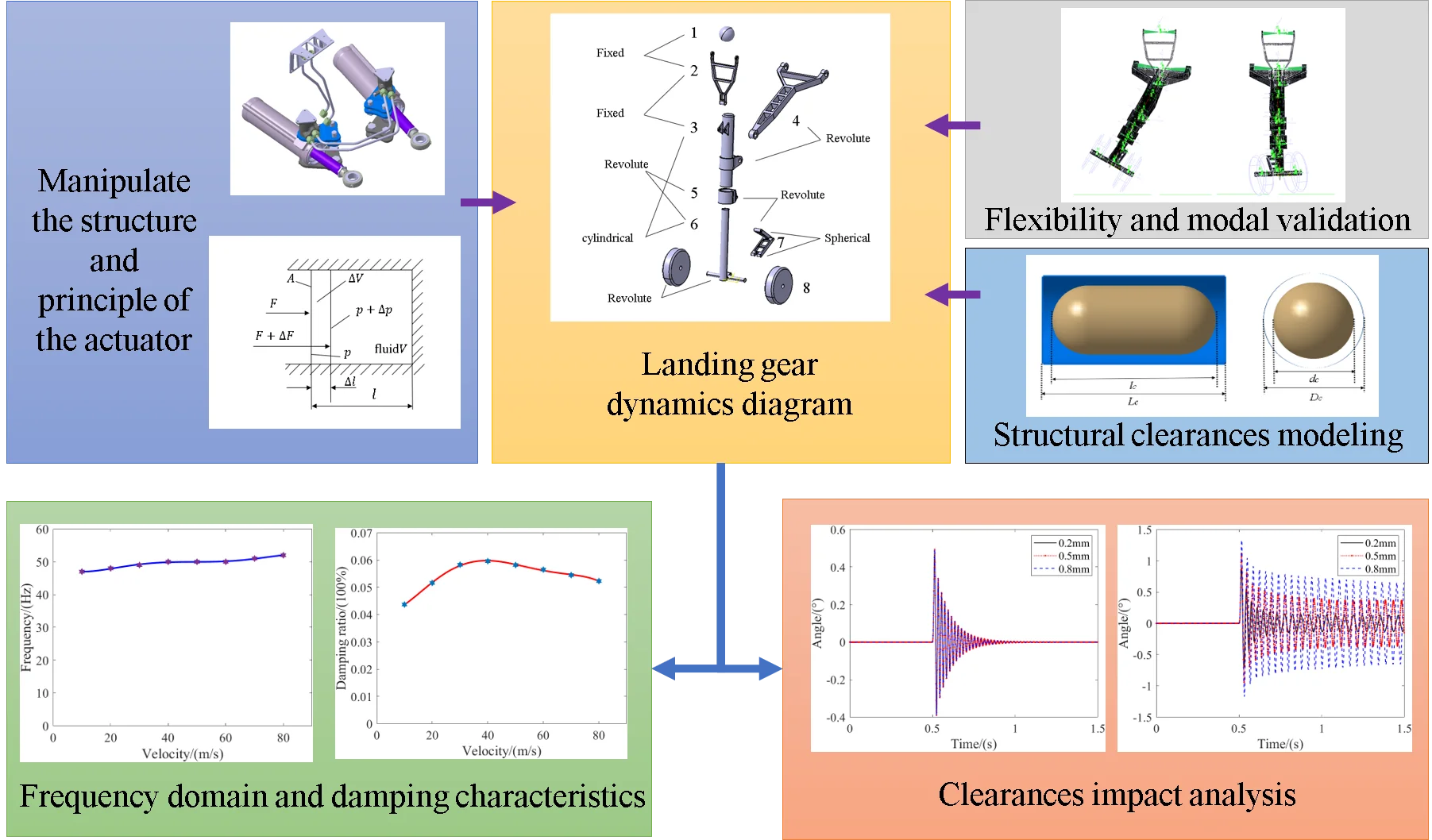
Highlights
- For the first time, a mechanistic study and analysis were conducted on the shimmy under controlled states, analyzing the frequency domain and damping characteristics of the system.
- Flexible modeling and processing were carried out on the shimmy dynamics system, and point line flexible constraints were used to better simulate the dynamic stiffness changes during the compression process of the landing gear.
- On the basis of establishing a multi-body dynamics model considering structural clearances, the influence of gaps on system stability was analyzed.
1. Introduction
There are many factors that can cause aircraft landing gear shimmy, and the relationships between them are quite complex [1], such as clearance, strut stiffness, anti sway damping, and aircraft overspeed taxiing, all of which may cause shimmy. Some aircraft may experience shimmy when maneuvering turns, or may not have experienced shimmy before, but suddenly show shimmy after a period of use. After years of research, significant progress has been made in the numerical analysis methods of shimmy vibration analysis, and good handling has also been achieved for stability analysis of complex nonlinear systems [2]. However, the model reproduction of certain shimmy situations is still quite complex and difficult, and further research is needed.
Shimmy refers to the self-excited vibration that occurs during the operation of an aircraft, which may have a serious impact on the safety and flight comfort of the aircraft. To avoid shimmy problems, a series of measures can be taken to improve the stability of the aircraft and reduce vibration. The most common and effective method among them is to use a shimmy reducer [4]. However, it should be noted that in some cases, the aircraft may be in a controlled state, and high-frequency equal amplitude vibrations often occur after losing the damping effect, which can interfere with the normal control and operation of the aircraft [5].
Research has shown that the occurrence of torsional clearance greatly reduces the critical speed of shimmy and is an important nonlinear factor causing nose landing gear shimmy [6]. For rotating components, due to the presence of fitting clearances, collisions and friction between constructions will increase, while also increasing part wear, resulting in larger clearances [7]. At present, there are many mathematical methods for analyzing shimmy clearance, including integration method [8], descriptive function method, multiscale method, incremental harmonic balance method, etc. [9]. In recent years, the use of bifurcation theory to explore clearance problems in the field of shimmy has begun to rise [10].
WR Krüger summarized the latest progress in numerical simulation of landing gear dynamics and introduced how to use numerical analysis methods to solve landing gear vibration problems [11]. Mi Sen [12] first used the descriptive function method to handle the clearance model and study the effect of clearance on the dynamic clearance problem of shimmy. Howcroft [13] established a functional expression for the torsional clearance torque when studying the problem of landing gear shimmy clearance, and smoothed it into segmented functions, which made mathematical analysis more convenient. Ruan [14] analyzed the dynamic effects of clearance in shimmy by establishing discrete clearance mechanics models for two common aircraft sliding states, namely the reduced sway state and the control state. Mohsen [15] analyzed the coupling effect between clearance and Coulomb friction torque.
In addition to the theoretical part, research on the dynamics module is also advancing with the maturity of computer technology. At present, research on the clearance type shimmy problem of landing gear is mainly based on the flexible multibody dynamics of landing gear [16]. Yan [17] has established a comprehensive model of three-dimensional rotating joints with clearance in mechanical systems. Based on this, Ruan [18] established four types of clearances through the transmission methods in the landing gear structure and analyzed the effects of each type of clearance. Feng [19] established a landing gear shimmy model with three-dimensional joint clearances and found that the interaction between each joint clearance is closely related to the analysis of shimmy stability. Zhuravlev [20] concluded through shimmy vibration tests and extensive experimental analysis that clearance may be the direct cause of induced shimmy vibration.
In the existing research on the clearance of landing gear structures, there is relatively little research on the influence of clearance on the stability of shimmy, and the problem of shimmy under control is becoming increasingly serious. This chapter is based on LMS Virtual.Lab dynamics software platform is used to establish an aircraft sway dynamics model considering the clearance between landing gear structures for dynamic simulation. The stability of the control system and the influence of clearance are studied, providing reference for aircraft anti sway design, nose landing gear fault diagnosis, and nose landing gear maintenance support.
2. Dynamic modeling of landing gear shimmy
2.1. Calculation method for oil stiffness
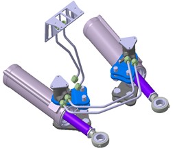
In the controlled state, modern fighter jets may experience shimmy, whether during straight-line taxiing or turning. In this state, the rotation of the landing gear is supported by two hydraulic actuators, which are filled with high-pressure oil, thereby limiting the freedom of the landing gear to twist.
The compressibility of the oil and the deformation of the anti torsion arm of the landing gear can cause significant torsional resistance to the struts during relative rotation, which limits the free deflection of the front wheels of the landing gear. This torsional resistance is directly proportional to the torsional angle:
where, represents the torsional stiffness of the actuator, and represents the rotation angle of the actuator. Based on the structural parameters, namely the distance between the two axes, the inner diameter of the piston rod, and the volume modulus of elasticity of the hydraulic oil, the overall torsional stiffness of the steering system in the operating state can be calculated.
Fig. 1Schematic diagram of operating the actuator
The liquid enclosed in a container acts like a spring under external force, increasing the force and decreasing the volume; The external force decreases and the volume increases. As shown in Fig. 2, when the pressure bearing area of the liquid remains constant, its hydraulic spring stiffness can be calculated by the pressure change ( is the external force change value), volume change ( is the liquid column length change value), and bulk modulus, that is:
Among them, is the bulk modulus of elasticity of hydraulic oil, which is often taken as 0.7×10³ MPa in engineering calculations.
Fig. 2Calculation of hydraulic spring stiffness
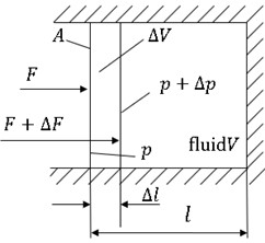
In the landing gear turning mechanism, A can be regarded as the oil pressure area of the turning actuator, can be regarded as the oil volume inside the turning actuator, and the hydraulic torsion spring stiffness of a single turning actuator:
Among them, represents the change in turning torque, and represents the change in sleeve angle.
If the distance between the axis of the turning actuator and the axis of the pillar is , then and , so:
Under existing simulation and mathematical models, conduct simulation research on the stability characteristics of the nose landing gear shimmy, and analyze the shimmy performance of the landing gear under different torsional stiffness conditions.
2.2. Shimmy dynamics model
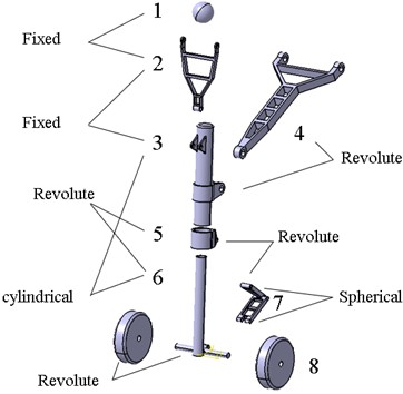
There are many parts of the landing gear itself. The simplified nose landing gear only includes the following parts: simplified fuselage mass point, diagonal strut, rocker arm, upper and lower torsion arms, strut outer cylinder, sleeve, left and right wheels, and piston rod.
Based on the motion form of the landing gear and the relationship between adjacent parts, appropriate motion pairs are defined for the entire system. The following diagram shows the motion pair relationship of the nose landing gear system, selecting four types of motion pairs: fixed pair, revolute pair, cylindrical pair, and spherical pair.
Fig. 3Landing gear dynamics diagram
Buffer is a key component of the landing gear system, used to absorb the impact force of landing gear. The landing gear of the simulation model adopts a single cavity buffer. In the analysis, we only considered the two main components of the buffer: the pillar outer cylinder and the piston rod and ignored the details of the internal hydraulic transmission. We mainly focus on the effects of two forces: one is the force generated by the air spring, and the other is the force generated by the oil damping. These forces [21] can be simulated in a functional manner through the theory of single cavity buffers.
Air spring force:
where, is the effective compressed air area of the piston; is the initial inflation pressure of the buffer chamber; is atmospheric pressure; is the initial volume of the buffer chamber; is the gas variability index, usually ranging from 1.05 to 1.3.
Fluid damping force:
where, is the oil density; and are the contraction coefficients of the main oil hole and the return oil hole, respectively; and are the effective oil pressure area of the buffer piston and the effective oil pressure area of the return chamber, respectively; and are the main oil hole area during the forward and reverse stroke of the buffer, respectively; and are the oil hole areas during the forward and reverse strokes of the return chamber, respectively.
In the rolling tire model, the most important factor is the lateral stiffness, which is related to the tire parameters and compression amount. The expression is as follows:
where is the lateral stiffness of the tire, is the compression amount, is the tire diameter, is the tire width, is the tire inflation pressure, and is the rated inflation pressure of the tire, is the lateral coefficient of the tire, depending on the tire type. For Type I tires, 63 is taken, for Type III tires, 69 is taken, and for Type VII tires, 57 is taken:
where is the lateral force of the tire,is the side slip angle, and is the side slip angle when the tire slips.
2.3. Establishment of flexible shimmy model
In general, when studying multi-body system dynamics problems, it is assumed that all components are rigid bodies (the distance between any two points inside each component remains constant). However, as some components of the mechanical system develop towards high-speed, lightweight, thin-walled, and other directions, there are situations where the dynamic deformation of the components is strictly required, and it is necessary to accurately grasp their dynamic deformation.
The method of handling flexible bodies in LMS Virtual. Lab Motion is to connect the finite element model of the flexible body through hinges, force elements, and other rigid and flexible bodies to create a high fidelity simulation model. The simulation result of flexible parts is the superposition of internal linear elastic deformation and the entire part experiencing nonlinear large displacement motion. The flexibility inside the component is obtained by synthesizing the results of finite element modal analysis, which is called component modal synthesis method or modal superposition method. A flexible component is represented by a set of flexible body modes, and the principal mode is used to represent the natural vibration of the component, which is determined by the geometric shape and material properties of the component itself. It is divided into free principal mode and fixed principal mode; Static mode is used to represent local loads and deformations caused by coupling with other components through hinges, force elements, etc. It includes rigid body mode, static constraint mode, static additional mode, and inertia release mode.
This article adopts the substructure modal synthesis method to handle the flexibility of components, dividing complex structures into several substructures according to their structural characteristics, and using finite element method to analyze the stress of each substructure to obtain the modal. The widely used flexible multibody dynamics processing method today is the modified Craig Bampton modal synthesis method. The structural dynamics equation of a substructure (i.e. a single flexible body) is:
where is the mass matrix of the substructure, is the damping matrix, is the stiffness matrix, and is the external force matrix.
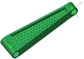
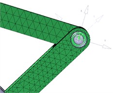
Firstly, individual parts are individually softened, and a three-dimensional tetrahedral mesh is generated using geometric entities. Through mesh pairing, the connection points are implemented using a spider mesh. The materials used in this experiment are isotropic steel materials. The following diagram shows the schematic diagram of the flexible body of the torsion arm.
Fig. 4Flexible body diagram of a single component
When studying the sliding performance of landing gear, the interaction between the piston rod and the outer cylinder is quite complex. When an airplane is taxiing on the ground and encounters bumps or bumps on the road surface, the piston rod will move back and forth inside the outer cylinder, causing changes in the length of the landing gear and affecting its stiffness.
Fig. 5Point line soft contact model
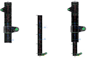
In kinematics, point line constraint refers to constraining the motion of an object by specifying that a specific point on the object moves along a specific path. This constraint is typically used to describe the motion of a rigid body, where the trajectory of one or more points is constrained by a linear or nonlinear path, using point line soft contact.
Fig. 6Lateral and torsional modes of landing gear
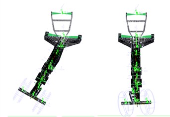
After establishing the dynamic model of the entire nose landing gear shimmy, modal analysis is required, with boundary conditions set as follows: 1. The connection point of the upper fuselage of the landing gear is fixed; 2. The landing gear's various motion pairs are set as fixed pairs; 3. Release the contact force between the tire and the ground. Obtain the following modal information:
Because the main impact of landing gear shimmy comes from lateral deformation and torsional deformation, and the influence of heading is relatively small, these two modes are listed in Table 1.
Table 1Modal data of landing gear
Working condition | Motion |
First-order lateral bending | 29 Hz |
First-order torsion | 145 Hz |
3. Analysis of system shimmy characteristics
3.1. System stability analysis
The shimmy stability under landing gear control refers to whether the shimmy or vibration of the landing gear system of the aircraft can be maintained within an acceptable range on the ground or during flight, without generating excessive vibration or instability. Excessive shimmy may cause failure of the landing gear system or affect the safety of ground operations, takeoff, and landing roll. Under the control state, shimmy is a self-excited vibration. Since the system does not have external dampers to reduce shimmy, it can only rely on its own structural damping. Therefore, solving the shimmy problem is best to start from the landing gear design stage, determine the landing gear structural parameters based on the overall parameters, so that the aircraft can have stable shimmy from the front in various rolling conditions, and ensure sufficient stability range under external interference.
The stiffness of the system in the direction of torsion is equal to the torsional stiffness provided by the torsion arm from the system sleeve to the wheel axle and the stiffness of the control actuator itself. Firstly, the influence of the hydraulic stiffness of the control actuator on the shimmy is analyzed. Through comparative analysis, as shown in the Fig. 7.
Fig. 7The influence of hydraulic stiffness on the control actuator
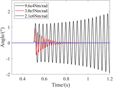
As shown in the Fig. 7, when the stiffness of the system is low, the shimmy angle diverges and the shimmy frequency is 28.5 Hz. The stability of the system is poor. However, when the stiffness of the control system is high and the system is subjected to the same amount of excitation, the shimmy angle will be small and will converge quickly. This indicates that for the landing gear system, the greater the torsional stiffness in the control state, the better the system stability and can avoid shimmy.
3.2. Frequency characteristic analysis
FFT algorithm is a fast algorithm for discrete Fourier transform, which can transform time-domain signals into frequency-domain. Some signals are difficult to discern in the time domain, but if transformed into the frequency domain, the features can be easily identified. The FFT algorithm is an improved version of the discrete Fourier transform algorithm based on its odd, even, imaginary, real, and other characteristics. The basic principle of FFT algorithm is to assume , and after performing parity processing, it has:
The larger , the more prominent the effect of FFT algorithm on improving computational efficiency. This article analyzes the principle of FFT and implements an FFT algorithm that can perform discrete Fourier transform on a given time-domain signal to obtain the frequency spectrum of the shimmy signal and display it on the graph.
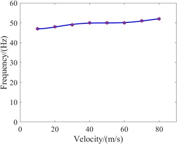
As shown in the Fig. 8, the shimmy frequency of the nose landing gear system is 50 Hz, which is different from the reduced shimmy state. Its frequency is generally higher. Analyzing the frequency of the system can provide a good understanding of the overall stiffness characteristics of the system, and provide certain guidance for design. In addition, it is necessary to study the influence of speed on the shimmy frequency in the control state and the shimmy frequency range. Through analysis, the following frequency range curve is obtained.
According to the legend, it can be seen that as the speed increases, the frequency of landing gear shimmy gradually increases. Within the range of speeds from 10 m/s to 80 m/s, the frequency increases from 47 Hz to 52 Hz, and the amplification range is not significant.
Fig. 8Frequency domain analysis diagram
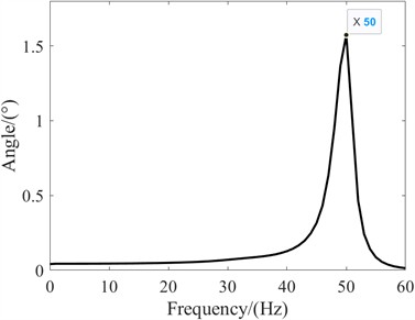
Fig. 9The relationship between frequency domain and velocity
4. Damping characteristic analysis
The actual system is mostly under damped, and the damping ratio is generally less than 0.2. So, the so-called free vibration of the damping system usually refers to the situation of under damping. Similarly, in order to avoid the occurrence of landing gear shimmy, the real landing gear system is under damped. Now let's analyze its vibration characteristics. The free vibration amplitude of the damping system decays exponentially. The free vibration of a damping system is a non-periodic vibration, but the time interval between two adjacent passes through the equilibrium position in the same direction is the same. The period of the attenuated vibration only indicates that it has isochronism and does not necessarily mean that it has periodicity.
Fig. 10Control state swing angle attenuation curve
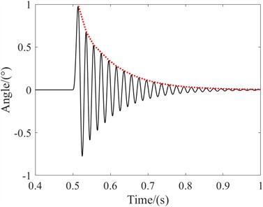
Fig. 11Damping ratio at different speeds
Damping vibration frequency and damping vibration period are important parameters for the free vibration of damping systems. When the damping ratio is very small, the difference between them and the natural frequency and natural period of the system is very small, even negligible. To describe the speed of amplitude attenuation, the logarithmic attenuation rate of amplitude is introduced. It is defined as the natural logarithm of the ratio of adjacent amplitudes over a natural period, i.e:
From this, it can be seen that the logarithmic attenuation rate of amplitude depends only on the damping ratio. For small damping ratios, it can be approximated as:
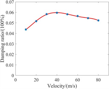
The numerical values for calculating the damping ratio of the system over the entire speed domain are:
According to the legend, it can be observed that the damping ratio of the landing gear first increases and then decreases with increasing speed. When the speed is 40 m/s, the maximum damping ratio of the landing gear is 0.0596, indicating that the system's shimmy performance is better at medium and low speeds, but it is more prone to instability at high speeds.
5. Stability analysis of shimmy system
5.1. Basic principles of clearance model
The dynamic models of mechanisms with clearances can be classified based on different features and modeling methods. Generally speaking, for small clearance models, assuming the clearance is small and can be approximated as a linear relationship, linear modeling methods are adopted. The large clearance model, considering the large clearance, requires the use of nonlinear modeling methods to accurately describe the effects of the clearance, such as the nonlinear characteristics during clearance closure and opening.
Pay attention to the stability and dynamic response of the system, such as studying the influence of clearances on system vibration. The motion pair of the nose landing gear sway model discussed in this article is mostly in the form of a rotating pair of shaft pins and shaft sleeves. Therefore, nonlinear springs and damping elements are used here to describe the stiffness and damping characteristics of the clearance.
Due to the presence of clearances, the position of the shaft pin in the shaft sleeve varies when subjected to different forces and moments. As shown in the Fig. 12.
Fig. 12Clearance diagram
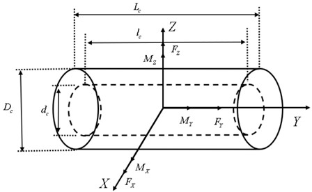
It is crucial to consider the accuracy and computability of the contact collision force model in the dynamic simulation of hole axis fit with structural clearances. These models need to comprehensively consider factors such as the material properties of the contact surface, mechanical shape, and the convergence of mathematical model calculations.
Among them, the Hertzian model is a widely used contact force model. This model simplifies contact collision into a spring damping system, where the stiffness term is a nonlinear function of the depth of embedding of the contact object. Meanwhile, dampers are used to simulate energy loss during contact processes. The expression for the normal contact force is as follows:
Fig. 13Collision diagram
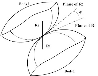
The contact stiffness coefficient can be expressed by the following expression:
where is the relative intrusion depth after the collision of two objects, is the recovery coefficient, is the penetration velocity, and there are also:
The damping coefficient can be expressed in the form of the following equation:
By using the Hertzian model, we can effectively describe the dynamic behavior of hole axis fit with structural clearances while considering system complexity, providing accuracy and reliability for simulation results.
5.2. Dynamic construction of clearance model
In LMS Virtual. Lab Motion, the contact force model covers various types, such as point-to-point contact, sphere stretching surface contact, sphere rotating surface contact, etc. Rotating pairs with clearances typically experience radial and axial clearances due to shaft hole fit tolerances and wear. In these cases, the radial contact force mainly occurs at the contact surface of the shaft hole, while the axial contact force is mainly generated at the two end surfaces of the structure.
To simulate this situation, this article attempts to establish a clearance model to describe the relationship between clearance and contact force. This model adopts the contact force form of the ball tensile surface contact model. The normal force is composed of nonlinear stiffness damping forces. Through this model, the dynamic behavior of rotating pairs with clearances can be more accurately described, thereby improving the accuracy and reliability of simulation.
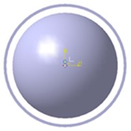
Install two components at the upper and lower torsion arms, one is a cylindrical shell, and the other is a central cylinder with hemispherical entities on both sides. Setting a certain distance between the cylinder and the cylindrical shell can be characterized as radial clearance. Similarly, setting the radius size of the hemisphere can simulate axial clearance, as shown in the schematic diagram of the radial and axial structural clearance models.
Fig. 14Clearance simulation schematic diagram
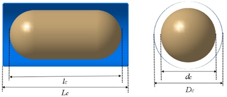
The ball stretch surface contact model in LMS Virtual. Lab can adjust the clearance size by adjusting the ball radius during the application process; By changing the Young’s modulus, Poisson's ratio, and recovery coefficient of the contact body, the Hertz force can be adjusted; By adjusting the spring coefficient and damping coefficient, linear and nonlinear spring damping forces can be adjusted.
In order to ensure that the nose landing gear model can accurately simulate various complex working conditions, it is necessary to verify the accuracy of the model in order to lay the foundation for subsequent simulation analysis. The verification process consists of two steps: first, rigid dynamic modeling of the nose landing gear is carried out without clearance, and then it is subjected to flexible processing, vibration simulation, and observation of swing angle parameters. At the same time, a rotating pair model is established using liner simulation, and the virtual model’s motion pair clearance is set to zero. By applying the same shimmy conditions for simulation, corresponding simulation curves can be obtained.
Fig. 15Clearance dynamics model
The “Angle” in the Fig. 16 represents the tire rotation angle during the landing gear sliding process, by comparing the three curves, it can be observed that they almost overlap. Therefore, it can be confirmed that the establishment of the model is basically accurate and can be used for subsequent dynamic analysis of shimmy with clearance.
Fig. 16Verification of clearance model
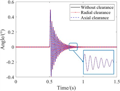
Fig. 17Radial clearance time-domain curve
5.3. The influence of structural clearance on shimmy
Based on the analysis of the connection form between the turning sleeve and the upper torsion arm in the nose landing gear in the previous section, a nose landing gear sway model with a clearance at the connection between the upper torsion arm and the lower torsion arm is constructed. The radial and axial clearances at the connection are adjusted to expand the influence of radial and axial clearances on the sway stability.
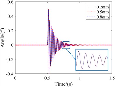
On the basis of establishing a landing gear shimmy model considering the radial clearance of the landing gear structure, the influence of landing gear structural clearance on shimmy dynamics was studied for different clearance sizes. By setting the radial clearance between the upper and lower torsion arms, with values of 0.2 mm, 0.5 mm, and 0.8 mm, the influence of radial clearance size on the handling state of landing gear shimmy was studied.
According to the legend, it can be observed that by comparing the time-domain curves of 0.2mm radial clearance, 0.5mm radial clearance, and 0.8mm radial clearance, at the same speed, the landing gear shimmy frequency is the same for different sizes of radial clearance, and the landing gear shimmy frequency is 49.2 Hz; The landing gear swing angle gradually converges with different radial clearance sizes, and the final angle converges to 0°. The time required for convergence to 0° is the same, and the peak swing angle is the same at different times. From this, it can be seen that the radial clearance has little effect on the shimmy frequency and stability of the landing gear in the control state.
On the basis of establishing a landing gear shimmy model considering the axial clearance of the landing gear structure, the influence of landing gear structural clearance on shimmy dynamics was studied for different clearance sizes. By setting the axial clearance between the upper torsion arm and the lower torsion arm, with values of 0.2 mm, 0.5 mm, and 0.8 mm, the influence of axial clearance size on the handling state of landing gear shimmy was studied.
According to the legend, it can be observed that by comparing the time-domain curves of the 0.2 mm axial clearance, 0.5 mm axial clearance, and 0.8 mm axial clearance, the larger the axial clearance, the worse the stability of the landing gear after being excited during sliding. The stable angles of the 0.2 mm, 0.5 mm, and 0.8 mm axial clearances are 0.135°, 0.364°, and 0.654°, and the landing gear shimmy frequency ultimately stabilizes at 18.2 Hz, 20.4 Hz, and 22.2 Hz. From this, it can be seen that axial clearance has a significant impact on the stability of the landing gear in the control state. The larger the axial clearance, the larger the initial angle of the landing gear, the larger the stable swing amplitude, and the higher the shimmy frequency.
Fig. 18Time domain curve of axial clearance
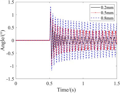
Fig. 19The influence of initial conditions on amplitude
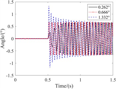
Similarly, in order to study the effect of initial deflection angle on the stable shimmy amplitude of the system, different initial excitations were given to change the system deflection angle. The relationship between the stability performance of the system and the initial conditions was analyzed as follows:
As shown in the figure, the research analysis shows that when the initial conditions of the system are 0.262°, 0.666°, and 1.332°, the nose landing gear system will vibrate uniformly at the end, with an amplitude of 0.666°, which is not affected by the initial conditions of the system.
Finally, change the torsional stiffness of the control actuator, considering 2e5 Nm/rad and 6e5 Nm/rad, set the axial clearance to 0.5 mm, and analyze the effect of stiffness on the amplitude of the swing angle.
Fig. 20The influence of stiffness on amplitude
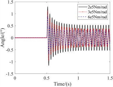
As shown in the Fig. 20, when the stiffness decreases, the system's swing angle increases significantly, with an amplitude of 0.534°, while when the stiffness increases, the amplitude is 0.334°. It can be seen that the increase in swing angle due to the decrease in stiffness is more significant, while the decrease in swing angle due to the increase in stiffness is not significant, showing a nonlinear relationship, and the swing angle amplitude will always be greater than the clearance value. Therefore, when setting up and landing gear, it is necessary to consider both the effects of stiffness and clearance, as well as the coupling effect between the two.
6. Conclusions
This article takes the aircraft nose landing gear system as the research object, analyzes the shimmy performance of the control state, considers the influence of structural clearance, and establishes a flexible body dynamic model of the aircraft nose landing gear with clearance. The following conclusions are drawn:
1) When the hour has just passed, it can lead to a decrease in system stability, and even shimmy; Generally speaking, in the manipulated state, the shimmy frequency of the system is higher than that in the reduced shimmy state; By analyzing the damping ratio of the system to determine its stability performance, it was found that the stability performance of high-speed sliding is worse than that of medium and low-speed sliding.
2) Based on the clearance dynamics model, it was found that the radial clearance has a relatively small impact on the shimmy; Axial clearance can cause equal amplitude vibration in the system, and the larger the clearance value, the greater the shimmy amplitude of the system; The initial excitation size does not affect the final system amplitude value; The system stiffness and clearance values affect the system amplitude, and the coupling effect between the two should be considered during design.
References
-
M. A. Padmanabhan and E. H. Dowell, “Landing gear design/maintenance analysis for nonlinear shimmy,” Journal of Aircraft, Vol. 52, No. 5, pp. 1707–1710, Sep. 2015, https://doi.org/10.2514/1.c033027
-
X. Du et al., “Shimmy dynamics in a dual-wheel nose landing gear with freeplay under stochastic wind disturbances,” Nonlinear Dynamics, Vol. 112, No. 4, pp. 2477–2499, Jan. 2024, https://doi.org/10.1007/s11071-023-09182-3
-
C. Arreaza, K. Behdinan, and J. W. Zu, “Linear stability analysis and dynamic response of shimmy dampers for main landing gears,” Journal of Applied Mechanics, Vol. 83, No. 8, p. 08100, Aug. 2016, https://doi.org/10.1115/1.4033482
-
M. Rahmani and K. Behdinan, “Structural design and optimization of a novel shimmy damper for nose landing gears,” Structural and Multidisciplinary Optimization, Vol. 62, No. 5, pp. 2783–2803, Jun. 2020, https://doi.org/10.1007/s00158-020-02628-x
-
H. Tourajizadeh and S. Zare, “Robust and optimal control of shimmy vibration in aircraft nose landing gear,” Aerospace Science and Technology, Vol. 50, pp. 1–14, Mar. 2016, https://doi.org/10.1016/j.ast.2015.12.019
-
N. K. Sura and S. Suryanarayan, “Lateral response of nonlinear nose wheel landing gear models with torsional free-play,” Journal of Aircraft, Vol. 44, No. 6, pp. 1991–1997, Nov. 2007, https://doi.org/10.2514/1.28828
-
X. Chen and S. Jiang, “Nonlinear dynamic behavior analysis of multi-linkage mechanism with multiple lubrication clearances,” European Journal of Mechanics – B/Fluids, Vol. 91, pp. 177–193, Jan. 2022, https://doi.org/10.1016/j.euromechflu.2021.10.006
-
D. Qin, B. Zhao, D. Gao, and L. Xu, “Thermal analysis model of scroll compressor with clearance leakage based on multiple scale method,” Journal of Thermal Analysis and Calorimetry, Vol. 147, No. 12, pp. 6893–6900, Mar. 2022, https://doi.org/10.1007/s10973-022-11282-y
-
Z. Lu, Z. Wang, Y. Zhou, and X. Lu, “Nonlinear dissipative devices in structural vibration control: A review,” Journal of Sound and Vibration, Vol. 423, pp. 18–49, Jun. 2018, https://doi.org/10.1016/j.jsv.2018.02.052
-
S. Ruan, M. Zhang, and H. Nie, “Research and analysis of coulomb friction in landing gear shimmy,” Journal of Aircraft, Vol. 61, No. 4, pp. 1143–1154, Jul. 2024, https://doi.org/10.2514/1.c037140
-
W. R. Krüger and M. Morandini, “Recent developments at the numerical simulation of landing gear dynamics,” CEAS Aeronautical Journal, Vol. 1, No. 1-4, pp. 55–68, May 2011, https://doi.org/10.1007/s13272-011-0003-y
-
M. S. Yi et al., “Non-linear shimmy analysis of a nose landing gear with free-play,” Journal of the Korean Society for Aeronautical and Space Sciences, Vol. 38, No. 10, pp. 973–978, Oct. 2010, https://doi.org/10.5139/jksas.2010.38.10.973
-
C. Howcroft, M. Lowenberg, S. Neild, B. Krauskopf, and E. Coetzee, “Shimmy of an aircraft main landing gear with geometric coupling and mechanical freeplay,” Journal of Computational and Nonlinear Dynamics, Vol. 10, No. 5, p. 05101, Sep. 2015, https://doi.org/10.1115/1.4028852
-
S. Ruan, M. Zhang, and H. Nie, “Influence of structural clearance on the shimmy characteristics of the landing gear during ground taxiing,” Journal of Vibration and Shock, Vol. 43, No. 2, pp. 234–243, Jan. 2024, https://doi.org/10.13465/j.cnki.jvs.2024.02.025
-
M. Rahmani and K. Behdinan, “Interaction of torque link freeplay and Coulomb friction nonlinearities in nose landing gear shimmy scenarios,” International Journal of Non-Linear Mechanics, Vol. 119, p. 103338, Mar. 2020, https://doi.org/10.1016/j.ijnonlinmec.2019.103338
-
F. Feng, Z. Chang, and H. Nie, “Analysis of influence of aircraft flexibility om nose landing gear shimmy,” Acta Aeronautica et Astronautica Sinica, Vol. 32, No. 12, pp. 2227–2235, Dec. 2011.
-
S. Yan, W. Xiang, and L. Zhang, “A comprehensive model for 3D revolute joints with clearances in mechanical systems,” Nonlinear Dynamics, Vol. 80, No. 1-2, pp. 309–328, Jan. 2015, https://doi.org/10.1007/s11071-014-1870-7
-
S. Ruan, M. Zhang, Y. Hong, and H. Nie, “Influence of clearance and structural coupling parameters on shimmy stability of landing gear,” The Aeronautical Journal, Vol. 127, No. 1315, pp. 1591–1622, Mar. 2023, https://doi.org/10.1017/aer.2022.109
-
G. Feng, B. Jiang, and Y. Jiang, “Effect of multi-joint clearance coupling on shimmy of nose landing gear,” Aerospace, Vol. 10, No. 11, p. 911, Oct. 2023, https://doi.org/10.3390/aerospace10110911
-
V. P. Zhuravlev and D. M. Klimov, “The causes of the shimmy phenomenon,” Doklady Physics, Vol. 54, No. 10, pp. 475–478, Oct. 2009, https://doi.org/10.1134/s1028335809100097
-
Y. Jiang, G. Feng, P. Liu, L. Yuan, J. Ding, and B. Jiang, “Evaluation of joint clearance effects on the shimmy of nose landing gear,” Aerospace, Vol. 10, No. 8, p. 722, Aug. 2023, https://doi.org/10.3390/aerospace10080722
About this article
This research was funded by Hunan Province Graduate Research Innovation Project (CX20210221).
The datasets generated during and/or analyzed during the current study are available from the corresponding author on reasonable request.
Guang Feng: investigation, methodology, writing-original draft. Jiang Bingyan: analysis, writing-review and editing. Shuang Ruan: simulation, drawing. Ming Zhang: validation, writing-review and editing.
The authors declare that they have no conflict of interest.
