Abstract
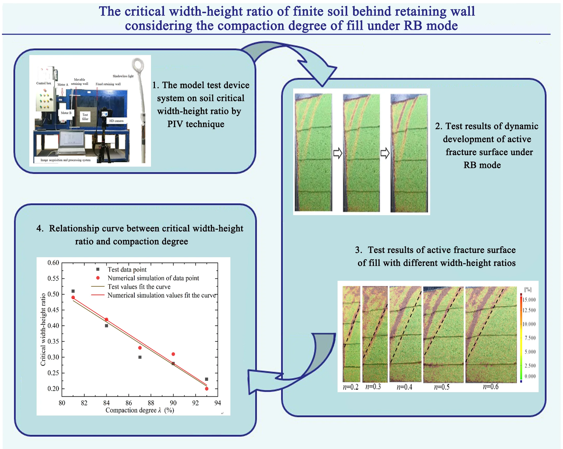
The compaction degree of fill is an important index for quality control of slope support engineering. Aiming at the influence factor of the compaction degree of fill, the effect of the compaction degree of fill on the characteristics of active fracture surface and the critical width-height ratio of finite soil under the RB model was investigated through laboratory model test and numerical simulation. The primary research findings are as follows: (1) Under RB mode, the active fracture surface of fill is an inclined plane that does not pass through the heel of the wall, and there are often multiple nearly parallel fracture planes in the fractured body. The active fracture surface of semi-infinite soil is between the movable retaining wall and the fill surface, and the finite soil is between the movable retaining wall and the fixed retaining wall. (2) For the loose finite soil (81 %), the upper point of the active fracture surface gradually moves upward from the fixed retaining wall to the fill surface with the increase of the compaction degree of the fill, the active fracture surface gradually becomes steeper, and the finite soil gradually changes into semi-infinite soil. (3) For loose semi-infinite soil (81 %), with the increase of compaction degree, the active fracture surface gradually becomes steeper, but the soil between the two walls is still semi-infinite. (4) Under the RB model, the critical width-height ratio of actively destroyed finite soil decreases linearly with the increase of compaction degree. After fitting, the empirical equations of the experimental and simulated values of the critical width-height ratio considering the compaction degree of the fill are given respectively. (5) Under the RB model, the active failure mechanism of fill is similar to the push slide of slope, and the development process of active failure surface is top-down sliding layer by layer. The research in this paper shows that the compaction degree of fill is an important factor affecting the characteristics of the fracture surface and the critical width to height ratio of the finite soil, and it is an important index to define the finite or semi-infinite state of the soil behind the wall.
Highlights
- The effect of the compaction degree of fill on the characteristics of active fracture surface and the critical width-height ratio of finite soil under the RB model was investigated.
- Under the RB model, the active failure mechanism of fill is similar to the push slide of slope, and the development process of active failure surface is top-down sliding layer by layer.
- Under the RB mode, the active fracture surface of fill is an inclined plane that does not pass through the heel of the wall, and there are often multiple nearly parallel fracture planes in the fractured body.
- Under the RB model, the critical width-height ratio of actively destroyed finite soil decreases linearly with the increase of compaction degree.
1. Introduction
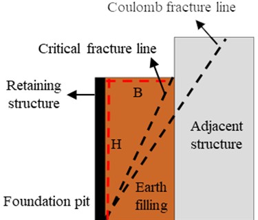
The calculation of earth pressure behind retaining wall has always been a hot topic in the field of geotechnical engineering, and the compaction degree of earth filling behind retaining wall is an important index in slope retaining engineering [1-3]. When the retaining wall is close to the existing underground structure, the width of the soil behind the wall is limited. When the limit state is reached, the soil fracture surface cannot be exposed to the ground due to the adjacent underground structure, which does not conform to the assumption of semi-infinite body in classical theory [5-7]. In this case, the soil between the retaining wall and the underground structure is called finite soil. The calculation methods of earth pressure of semi-infinite soil behind retaining wall are different from those of finite soil. At present, the earth pressure of semi-infinite soil is generally calculated by classical earth pressure theory, while the earth pressure of finite soil is calculated mainly by the local experience method because there is no uniform standard to follow [9-11]. Therefore, before calculating the earth pressure, it should be determined whether the soil behind the wall is semi-infinite or finite. In most of the existing literature, the width-height ratio of fill is used to define whether there is finite soil behind the wall. The schematic diagram of finite soil is shown in Fig. 1, is the filling width and is the filling height, when the fracture surface of fill passes through the intersection of the ground and the adjacent underground structure, the corresponding width-height ratio of fill is the critical ratio of finite soil , and is the filling critical width and the filling critical height, respectively.
Fig. 1Critical width-height ratio of finite soil
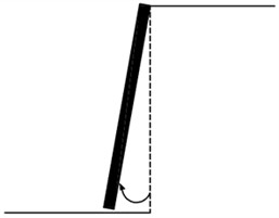
The model test is the most intuitive means for researchers to explore the nature of the problem. Scholars at home and abroad have carried out a large number of model tests on the active failure of fill behind the wall, and achieved relatively abundant research results, but the influence of the compaction degree of fill is rarely considered in the tests. The schematic diagram of three active displacement modes of the retaining wall is shown in Fig. 2; the translation mode (TT mode), the rotating around base mode (RB mode), and the rotating around top mode (RT mode) is a translational mode of wall, a mode of rotation around the bottom of the wall, and a mode of rotation around the top of the wall, respectively. Wang [12], Jiang [13], Dai [14], Fang [15], and other scholars carried out active failure model tests of non-cohesive sandy soil under three retaining wall displacement modes, analyzed the development process and morphological characteristics of the fracture surface of fill with different width-height ratios, and obtained the critical width-height ratio range of finite soil under three retaining wall displacement modes. Based on Particle Image Velocimetry (PIV) technology, Niedostatkiewicz et al. [16] and Xia [17] conducted active failure model tests for non-cohesive soil, and obtained the active deformation characteristics and fracture surface morphological characteristics of different widths of fill under RB mode. Through laboratory model test, Hu [18] obtained the active deformation and failure process, fracture surface morphology, and soil pressure distribution characteristics of sand behind cantilever retaining walls with different width and height ratios under RB mode. Li [19] used the self-developed model test device to study the deformation and failure mechanism of non-cohesive soil with different widths behind the rigid retaining wall and the active earth pressure distribution characteristics. By using PIV technology and image analysis software, the shear strain and displacement vector diagram of filled soil with different widths were obtained. Using the self-developed model test device, Chen [20] carried out the active failure model test of fill with different compaction degree under TT mode. Based on PIV technology and image analysis software, the influence law of compaction degree on the formation process and morphological characteristics of the fracture surface of non-cohesive fill was obtained, and it was proved that compaction degree of fill is an important factor affecting the critical width-height ratio.
Fig. 2Schematic diagram of three active displacement modes of retaining wall
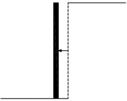
a) TT mode
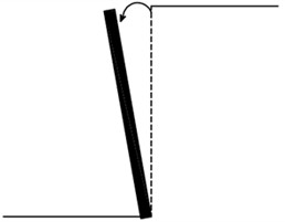
b) RB mode
c) RT mode
Due to the advantages of numerical simulation, such as low cost, short time and easy parameterization, many scholars have adopted this method to study the active deformation and failure of soil behind walls. Based on the DEM and PFC2D numerical calculation software [21-24], the numerical simulation of the active deformation and failure process of soil behind the wall under RB mode is conducted, and the morphological characteristics of the active fracture surface of soil under different width-height ratios were obtained. When the width-height ratio 0.7, the morphology of the fracture surface does not change with the increase of width-height ratio n, and it can be regarded as reaching the critical state of finite soil. Wan [25] used the discrete element software PFC2D to calculate and analyze the influence of the friction Angle between wall and soil on the active deformation and failure characteristics of non-cohesive soil with different width-height ratios and the soil pressure distribution law. Huang [26] used the finite element analysis software ABAQUS to study the development law and morphological characteristics of the active plastic zone of non-cohesive soil behind the wall under RB mode. The results show that the plastic zone is first formed on the soil surface, and gradually increases from top to bottom with the increase of wall displacement until the active limit state. Zeng [27] used the discrete element software PFC2D to simulate the passive earth pressure of the rigid retaining wall under the three displacement modes of TT, RT and RB, gave the distribution diagram of the passive earth pressure behind the wall and the corresponding vertical stress distribution diagram, and obtained the change law of the earth pressure behind the wall with the displacement of the wall. Lin [28] studied the effects of the geometry of filling behind the wall and the friction between the wall and soil on the finite soil failure mode and principal stress rotation through numerical simulation. The research shows that the soil fracture surface develops from the bottom of the movable retaining wall to the fixed retaining wall in RB mode, and the plastic failure zone can be described as an irregular quadrangle. Benmebarek [29] used discrete element software FLAC2D to conduct numerical simulation and analysis of the active earth pressure of rigid retaining wall under multiple working conditions, and obtained the distribution law of active earth pressure under TT, RB and RT displacement modes of retaining wall.
In response to the problem of active earth pressure behind retaining walls, some scholars conducted relevant theoretical research. Huang [30] proposed a method for calculating the finite earth pressure behind retaining walls using the arc-shaped principal stress trajectory, verified the rationality of the method, and proposed a formula for calculating the critical width of finite earth bodies. Lin [31] proposes an active earth pressure solution model that considers retaining structure stiffness and displacement. The model is based on the Modified Coulomb earth pressure theory and assumes a linear relationship between lateral earth pressure and displacement. The proposed model was compared with existing data, and degradation verification was performed, the verification results are in good agreement. Liu [32] incorporates seismic effects by integrating horizontal seismic coefficients into the equations through the pseudo–static model. From the work–energy balance principle, a closed-form formulation for seismically active earth thrusts was developed. An optimization program was utilized to identify the most critical solution. The effectiveness of the proposed approach was verified by contrasting it with established research methodologies. Based on differential element methods and wedge limit equilibrium method, Xiong [33] derived the active earth pressure calculation formula of balance weight retaining wall under translational displacement mode. According to the parameter analysis, the interface friction resistance escalates alongside the rise in the boundary friction angle. The active earth pressure resultant force of the retaining wall increases with the increase of the width to depth ratio of filling, and decreases with the increase of the friction angle of filling.
To summarize, the majority of current research on the finite soil behind retaining walls focuses on loose fill generated under free-falling sand conditions as the subject of study. However, these studies fail to consider the compaction requirements for engineering practice; the findings do not directly provide guidance for practical applications. The compaction degree of fill is an important factor that impacts the quality of slope support engineering. Therefore, it is essential to consider the compaction degree of fill when studying finite soil active soil pressure. Currently, there is a limited amount of literature considering the influence of filling compaction degree on the study of finite soil pressure. Therefore, this paper conducts model tests and numerical simulations to investigate the critical width-height ratio of finite soil under the RB model, using river sand from Dongting Lake in east Yueyang as the test fill. This study reveals the relationship between the compaction degree behind the wall and fracture surface characteristics, as well as the critical width-height ratio of finite soil. This paper improves the theory of soil pressure calculation for limited soil mass and provides valuable first-hand data for slope support structure design and construction, which has certain theoretical value and practical engineering significance.
2. Physical and mechanical index test of fill
In order to facilitate the development of subsequent model tests and the value of numerical simulation parameters, the basic physical indexes of the fills and the relationship formulas between compaction degree and density, compaction degree and internal friction angle are obtained through indoor soil tests.
2.1. Physical index test of fill
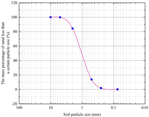
The fill used in the test is brownish-yellow and cohesionless sand, taken from the East Dongting Lake in Yueyang. To ensure the accuracy and reliability of the test, the sand is screened, cleaned and dried. Relevant tests are carried out in accordance with the geotechnical test methods and standards GB/T50123-2019, the air-dried moisture content ω of the fill is 1.8 %, and the maximum dry density , the particle size distribution curve of the fill (as shown in Fig. 3) is mainly concentrated between 0.5 mm and 2 mm. The non-uniformity coefficient 2.9, and the curvature coefficient 1.4, which is the coarse sand with poor gradation.
Fig. 3Grain grading curve of fill
2.2. Test on relationship between compaction degree and density of fill
In order to obtain the relationship formula between compaction degree and density of fill, 11 groups of density tests with different hammer numbers (hammer weight 10 kg) are designed. The layered hammer numbers are 0 (free shakeout condition), 1, 3, 5, 10, 20, 30, 40, 50, 60, and 70, respectively. The test operation and data processing methods are as follows:
(1) Forming a fill container. Adjust the distance between the movable retaining wall and the fixed retaining wall to create a 400 mm length, 200 mm width, and 400 mm height rectangular space for filling with soil in the model box, with a volume of 32000 cm3.
(2) Filling soil. The impact filling is divided into 4 layers, and the thickness of each layer is 100 mm. Before hammering, the thickness of the virtual laying should be greater than 100 mm. Firstly, the first layered sand with a thickness of about 120 mm is evenly laid at the bottom of the box, and a load steel plate (length, width, and thickness are 400 mm, 200 mm, and 15 mm, respectively) is placed on it. 10 kg hammer is used to continuously impact the steel plate, and the number of impact reaches the number of test design. The steel plate is removed, and the first layered surface is shaved with a brush to flatten to a 100 mm thick scale line, and a black sand line is laid near the glass to complete the laying of the first layered sand. The same method is used for the next three layers. After the fourth layer is leveled, the surface of the sand reaches the 400 mm scale line.
(3) Taking out fill and weighing. Open the sand leakage hole at the bottom of the box, take the compacted sand out of the box, and weigh its weight (g) with an electronic scale.
(4) Data arrangement and calculation. The density of sand to each hammering number is calculated by , the dry density is calculated by , and the compaction degree is calculated by . In the formula, the moisture content of the fill is 1.8 %, and the maximum dry density 1.72 g/cm3. The calculation results on density, dry density and compaction degree of filling under different hammer counts are detailed in Table 1.
By fitting the experimental data in Table 1 by data analysis software origin based on nonlinear least square method, the relationship between the filling density and the compaction degree is obtained as Eq. (1). The increases linearly with the increase of , and the correlation degree 0.999, showing a high linear correlation:
Table 1Density, dry density and compaction degree of filling under different hammer counts
The number of hammer strokes | 0 | 1 | 3 | 5 | 10 | 20 | 30 | 40 | 50 | 60 | 70 |
Density (g/cm3) | 1.41 | 1.45 | 1.47 | 1.50 | 1.53 | 1.62 | 1.67 | 1.70 | 1.72 | 1.73 | 1.73 |
Dry density (g/cm3) | 1.39 | 1.42 | 1.44 | 1.47 | 1.50 | 1.59 | 1.64 | 1.67 | 1.69 | 1.70 | 1.70 |
Compaction degree (%) | 80.8 | 82.6 | 83.7 | 85.5 | 87.2 | 92.4 | 95.3 | 97.1 | 98.3 | 98.8 | 98.8 |
2.3. Test on relationship between compaction degree and internal friction angle of fill
In order to determine expediently the internal friction angle of fill with different compaction degree in the process of numerical simulation, it is necessary to obtain the relationship between the compaction degree and internal friction angle of fill. Therefore, five groups of direct shear tests with the compaction degree of 80.8 %, 83.7 %, 87.2 %, 95.3 % and 98.3 % are carried out, respectively; and the under the corresponding was obtained. The following is a description of the test method with a of 87.2 %:
(1) According to the Eq. (1), the fill density ρ corresponding to 87.2 % of is 1.508 g/cm3, the volume in the shear box is 60 cm3, and the corresponding sand mass is 90.5 g.
(2) Weigh 90.5 g fill, pour it into the shear box and compact it, the sample's surface is aligned with the 2 cm scale line of the shear box, cover the load plate, and push the shear box under the pressure frame.
(3) Zero the dial indicator pointer, apply a vertical pressure of 100 kPa, remove the shear box bolt, apply shear force in the horizontal direction until the shear failure of the sample, and record the maximum of the dial indicator pointer before the shear failure of the sample.
(4) Reversing the handwheel to restore the shear box in situ, remove the vertical pressure, take out the sheared soil sample, and clean the shear box.
(5) Repeating the above steps, the shear tests are carried out under the vertical pressures of 200 kPa, 300 kPa and 400 kPa for the second to fourth group specimens (all with masses of 90.5 g).
(6) According to Coulomb strength theory, the internal friction angle is 37.8° of sand with a compaction degree of 87.2 %.
As shown in Table 2, according to the above test method, the internal friction angle of sand under different compaction degree is obtained. By data analysis software origin based on nonlinear least square method, the test data in Table 2 are fitted to obtain the relationship between and , as shown in Eq. (2). The correlation degree 0.986, which is highly linearly correlated:
Table 2Internal friction angle of sand with different compaction degree
Compaction degree (%) | 80.8 | 83.7 | 87.2 | 95.3 | 98.3 |
Internal friction angle (°) | 34.9 | 35.6 | 37.8 | 41.0 | 43.1 |
3. Research scheme and methods
In this paper, through the combination of model test and numerical simulation, the influence of compaction degree of soil behind wall on the critical width-height ratio of finite soil under RB displacement mode is explored.
3.1. Research scheme
To obtain the critical width-height ratio of fill with different compaction degrees, the research scheme is designed as shown in Table 3. In this study, 5 kinds of compaction degree fillings are designed, and each compaction degree of fill corresponds to 5 different width-height ratios. The minimum compaction degree of 81 % is corresponding to the completion of self-weight consolidation of sand under the condition of free drop sand.
Table 3Research scheme
Compaction degree (%) | Width-height ratio of soil | ||||
81 | 0.2 | 0.3 | 0.4 | 0.5 | 0.6 |
84 | 0.2 | 0.3 | 0.4 | 0.5 | 0.6 |
87 | 0.2 | 0.3 | 0.4 | 0.5 | 0.6 |
90 | 0.2 | 0.3 | 0.4 | 0.5 | 0.6 |
93 | 0.2 | 0.3 | 0.4 | 0.5 | 0.6 |
3.2. Introduction of model test
3.2.1. Test device
The model test device system (see Fig. 4) is mainly composed of a filling box, a movable retaining wall, a fixed retaining wall, a movable retaining wall displacement control system, and an image acquisition and processing system.
Fig. 4Model test device system
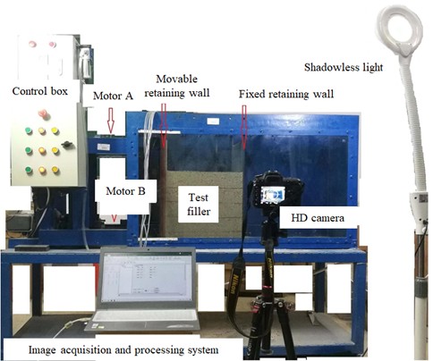
(1) Filling box: It is a steel structure cuboid with a size of length 1200 mm, width 400 mm, height 700 mm. The front of the box is 16mm thick transparent tempered glass to achieve real-time observation and dynamic photography during the test.
(2) Movable retaining wall and fixed retaining wall: the movable retaining wall is a 16 mm thick steel plate, and the upper and lower welding hinged supports on the outer side of the steel plate are hinged with the upper and lower loading drive shafts, respectively. The fixed retaining wall is a 12 mm thick steel plate, and the slot of the fixed retaining wall is set every 100 mm in the box to adjust the fill width to achieve different width-height ratios.
(3) Displacement control system of movable retaining wall: it is composed of two sets of three-phase asynchronous motors with the same performance, gear drive shaft, electric control box and fixed motor support. The power propulsion speed is 0.02 mm/s, and three kinds of retaining wall displacement modes can be realized. When motor A and motor B move to the left at the same time, TT mode under active condition can be realized. When motor A is stationary and motor B moves to the left, RT mode can be realized under active conditions. When motor A moves to the left and motor B is stationary, RB mode can be realized under active condition. The above three displacement modes can be controlled by buttons on the electric control box.
(4) Image acquisition and processing system: It is composed of a high-definition digital camera, shadowless light source, computer, and image processing software, etc., to achieve continuous photography and image processing analysis. During the test, a high-definition digital camera is used to automatically take photos of the filling area to ensure that the camera is perpendicular to the measurement surface, and the light source is placed on both sides of the test box to reduce the specular reflection.
In order to realize the non-contact measurement of soil deformation, PIV technology and GOM image analysis software are used to process and analyze the continuous photos. PIV technology is a non-contact and modern optical deformation measurement technology. Its basic working principle is to use two adjacent images of the surface of object to track the position change of the same pixel point to obtain the displacement vector of the point, and then calculate the displacement field and strain field of the whole surface. GOM is a non-commercial image analysis and processing software, which can be obtained for free. It has been widely used in non-contact deformation measurements of rock and soil.
3.2.2. Test method
The test method is described below by taking the compaction degree of 84 % and the width-height ratio of 0.5 (width 200 mm, height 400 mm) as an example:
(1) Test preparation: the movable retaining wall is positioned to the initial position, and the corresponding slot is selected to install the fixed retaining wall, so that the precise distance between the movable retaining wall and the fixed retaining wall is 200 mm; paste the strip wool at the connection between the retaining wall and the tempered glass to prevent sand leakage; paste transparent tape on both sides of the retaining walls and apply Vaseline to reduce friction, and wipe the inner and outer sides of the tempered glass with a dry cloth.
(2) Calculation of fill weight per layer: According to Eq. (1), the density corresponding to a compaction degree of 84 % is 1.453 g/cm3, the volume of filling soil per 100 mm thickness is 8000 cm3, and the weight is 11.62 kg.
(3) Sand filling: There are four layers of impact-filling sand, and each layer is 100 mm thick. Weigh 11.62 kg of sand into the filling box, and place a load steel plate (its length, width and thickness are 400 mm, 200 mm and 15 mm, respectively) on the sand surface. The steel plate is continuously impacted with a 10 kg hammer to the lower edge of the steel plate to be flush with the corresponding 100 mm scale line, and the steel plate is removed. The surface layer of the first layer is shaved with a brush, and a black sand line is laid near the glass. According to this method, the second, third and fourth layers are filled in turn. When the fourth layer is filled, the sand surface is flush with the 400 mm scale line.
(4) Test running: The high-definition camera, shadowless light source, and computer are arranged in the appropriate position, and the camera shooting frequency is set to 0.5 seconds/sheet. Turn off the indoor lights and close the curtains to create a dark room effect. The camera is opened to start the image shooting, and then the active retaining wall displacement control system is started immediately, so that the fill behind the wall is deformed in the RB displacement mode until the ultimate failure.
(5) Test termination conditions: When the black sand line has obvious dislocation or the filling surface has obvious cracks and the filling soil has obvious subsidence, the test can be ended.
(6) Image digital processing and analysis: The photos collected by the high-definition camera are imported into the GOM software for processing and analysis, and the shear strain cloud map of the soil behind the wall at each time point is obtained. The analysis of the cloud map can obtain the corresponding active fracture surface when the fill behind the wall reaches the limit state.
3.3. Introduction of numerical simulation
Considering that some working conditions in the research scheme are difficult to complete through model tests, this paper uses finite element software Plaxis2D to conduct numerical simulation analysis of some working conditions.
3.3.1. Establishment of finite element model
The following is an example of the establishment of the finite element model with the compaction degree 84 % and the width-height ratio 0.4. The finite element model is shown in Fig. 5; it is assumed that the walls on both sides are rigid plates, the left side is a moving plate, and the right side is a fixed plate. The interface element is used to simulate and define the interaction between the retaining wall and the filling on both sides. The bottom end of the moving plate is fixed, and the left displacement is applied to the top end, so that the moving plate rotates to the left around the bottom end, forming the RB displacement mode. By adjusting the internal friction angle, density, width-to-height ratio, and other parameters, the influence of filling compaction degree and width-to-height ratio on active deformation and failure of soil is obtained.
Plaxis2D offers 6-node and 15-node triangular elements. The ideal simulation results of the 6-node triangular element can only be obtained when the mesh is dense enough. The 15-node triangular element is highly precise, and more accurate calculation results can be obtained in numerical calculation. Therefore, the soil element in this paper adopts a 15-node triangular element, and the mesh division of the model is shown in Fig. 6.
Fig. 5Finite element model
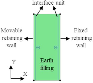
Fig. 6Model grid division
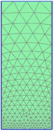
The constitutive relation of soil adopts the Mohr-Coulomb model, and the rigid retaining walls on both sides adopt the linear elastic model. According to Eq. (1), the unit weight of fill with different compaction degrees is calculated, and the corresponding internal friction angle is calculated according to Eq. (2), the specific unit weight and internal friction angle of fill with different compaction degree is shown in Table 4.
Table 4The specific unit weight and internal friction angle of fill with different compaction degree
Compaction degree (%) | Unit weight (kN/m3) | Internal friction angle (°) |
81 | 14.1 | 34.7 |
84 | 14.7 | 36.1 |
87 | 15.2 | 37.5 |
90 | 15.8 | 38.9 |
93 | 16.3 | 40.3 |
3.3.2. Verification of finite element model
Taking the compaction degree 84 % and the width-height ratio 0.4 as examples, the finite element model built in this paper is verified. Fig. 7 shows the active fracture surface of fill in RB mode, Fig. 7(a) is the model test result, and Fig. 7(b) is the finite element simulation result.
It can be seen from Fig. 7 that the calculation results of the active fracture surface of fill under RB mode are basically consistent with the test results, which are three nearly parallel linear strips, with similar inclination angles of the fracture surfaces and not passing through the heel of the wall; the finite element model established in this paper is reasonable and reliable.
Fig. 7Active fracture surface of filling under RB mode (λ= 84 %, n= 0.4)
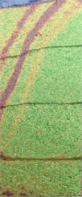
a) Test result
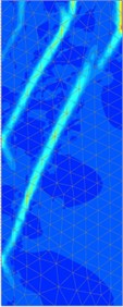
b) Simulation result
4. Result analysis
4.1. Dynamic development law of active fracture surface
Taking the semi-infinite soil test results of the compaction degree 87 % and the width-height ratio 0.4 as an example, the dynamic development law of the active fracture surface under RB mode is shown in Fig. 8.
Fig. 8Dynamic development of active fracture surface under RB mode (λ= 87 %, n= 0.4)

It can be seen from Fig. 8 that with the increase of the displacement of the movable retaining wall, the first black sand line from top to bottom appears to be obviously dislocation, followed by the second black sand line. The active fracture surface under RB mode starts from the fill surface, and then gradually develops obliquely downward. When the limit state is reached, multiple parallel fracture surfaces are formed inside the soil from top to bottom. The lower end of the outermost fracture surface stops at about 3/8 of the fill height above the wall heel, and the fracture surface does not pass through the wall heel.
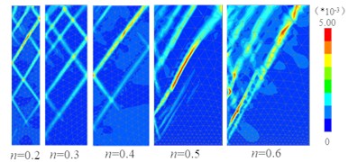
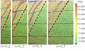
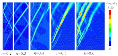
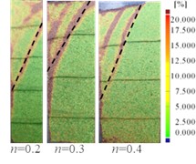
Fig. 9Test results and simulation results of active fracture surface of fill with different width-height ratios
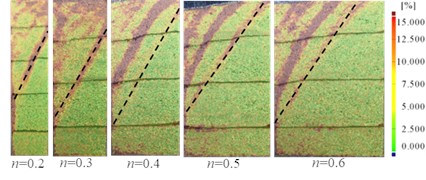
a)81 %, Test result
b)81 %, Simulation result
c)84 %, Test result
d)84 %, Simulation result
e) 87 %, Test result
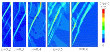
f)87 %, Simulation result
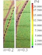
g)90 %, Test result
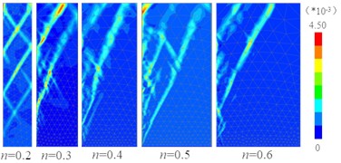
h) λ=90%, Simulation result
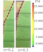
i)93 %, Test result
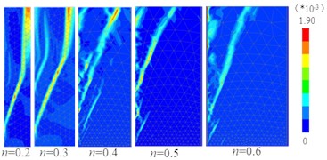
j)93 %, Simulation result
It can be seen that the development process of the active fracture surface of fill under RB mode is top-down sliding layer by layer, and its formation mechanism is similar to that of push landslide, that is, the upper soil first deforms, and then the lower soil is pushed and squeezed to make it deform and slide successively.
4.2. Morphological characteristics of active fracture surface of fill with different width-height ratios
Due to the limitation of test conditions, model tests have not been carried out in some working conditions in the research scheme, including (1) 84 %, 0.6; (2) 87 %, 0.5, 0.6; (3) 90 %, 0.4, 0.5, 0.6; (4) 93 %, 0.4, 0.5, 0.6, a total of 9 working conditions. The active fracture surface of 9 unfinished working conditions was obtained by numerical simulation. The model test results and numerical simulation results of the active fracture surface of fill with different width-height ratios under a certain compaction degree are shown in Fig. 9.
It can be seen from Fig. 9 that (1) The test results of the active fracture surface of the filling soil with different compaction degrees and different width-height ratios under RB mode are basically consistent with the simulation results. The outer edge of the active broken body is an approximately linear strip and does not pass through the wall heel, but the distance from the lower end of the outer edge of the active broken body to the wall heel obtained by the test is greater than the simulation results. (2) When the compaction degree is constant, with the increase of the width-height ratio, the upper end of the outer edge of the active broken body gradually moves up from the middle and upper part of the fixed retaining wall to the surface of the soil, the broken body changes from “trapezoid” to “triangle”, and the soil behind the wall gradually changes from finite soil to semi-infinite soil.
4.3. Influence of compaction degree on morphological characteristics of active fracture surface of fill
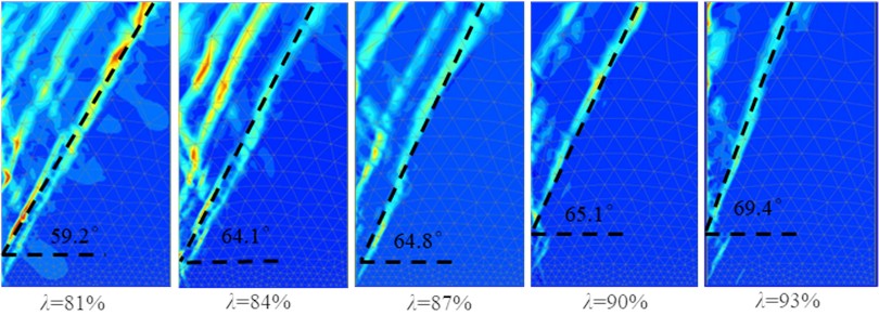
Taking the simulation results of the active failure surface of the fill with different compaction degrees under the width-height ratio 0.4 and 0.6 as an example, the influence of compaction degree on the active failure surface under the constant width-height ratio of fill is discussed, as shown in Fig. 10 and Fig. 11.
Fig. 10Active fracture surface of fill with different compaction degrees under width-height ratio n= 0.4
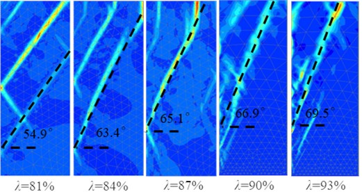
As can be seen from Fig. 10, when the width-height ratio 0.4, the morphological characteristics of the active fracture surface of fill under RB mode change with the increase of the compaction degree . When 81 % and 84 %, the fracture surface (as shown by the dashed line in Fig. 10) is all between the movable retaining wall and the fixed retaining wall, and the soil between the two walls is finite soil. When 87 %, 90 %, 93 %, the fracture surface is all between the movable retaining wall and the filling surface, and the soil is semi-infinite.
It can be seen that for the loose finite soil (81 %), with the increase of compaction degree, the upper point of the active fracture surface under RB mode gradually moves up from the fixed retaining wall to the filling surface, the fracture surface gradually becomes steeper, the volume of the fractured body gradually decreases, the plane shape of the fractured body changes from “trapezoid” to “triangle”, and the finite soil gradually becomes semi-infinite. It is proved that the degree of compaction is an important factor affecting the critical width-height ratio of finite soil.
It can be seen from Fig. 11 that when the width-height ratio 0.6, the active fracture surface (as shown by the dashed line in Fig. 11) of the fill with 5 kinds of compaction degree under RB mode is all between the movable retaining wall and the fill surface, the plane shape of the broken body is all “triangle”, and the soil between the two walls is semi-infinite. It can be seen that for loose ( 81 %) semi-infinite soil, with the increase of compaction degree, the active fracture surface gradually becomes steeper, and the volume of the broken body gradually decreases, the soil between the two walls is still semi-infinite soil.
Fig. 11Active fracture surface of fill with different compaction degrees under width-height ratio n= 0.6
4.4. Critical width-height ratio of considering the compaction degree of fill
4.4.1. Method for determining the critical width-height ratio of finite soil
Based on the shear strain cloud diagram and active fracture surface morphological characteristics of fill with different width-height ratio under each compaction degree, as shown in Fig. 9, the conditions under which the active fracture surface shape of fill with different width-height ratio is closest to the critical state under a certain compaction degree are found, and then the critical width-height ratio of finite soil under the compaction degree is determined according to the following method.
Fig. 12Schematic diagram for determining the critical width-height ratio (λ= 81 %, n= 0.5)
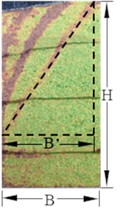
The method of determining the critical width-height ratio of finite soil is illustrated by taking the model test results of fill with different width-height ratios of the compaction degree 81 %. As shown in Fig. 9(a), the model test results of active fracture surface of five kinds of width-height ratio fill are compared when the compaction degree is 81%. It is found that when the width-height ratio 0.5, the upper point of the fracture surface (black dashed line in the figure) moves to the intersection point between the fixed retaining wall and the fill surface, and the width-height ratio of the fill is about to reach the critical value, and it can be speculated that the critical width-height ratio should be slightly less than 0.5.
The schematic diagram for determining the critical width-height ratio is shown in Fig. 12, where is the fill width and is the fill height, the critical width-height ratio is calculated as .
4.4.2. Relationship between critical width-height ratio and compaction degree
The test values and simulated values of critical width-height ratio of finite soil under 5 kinds of compaction degree determined by the above method are shown in Table 5.
Table 5Critical width-height ratio test value and simulation value
Compaction degree (%) | 81 | 84 | 87 | 90 | 93 |
Test value of critical width-height ratio | 0.51 | 0.40 | 0.30 | 0.28 | 0.23 |
Simulation value of critical width-height ratio | 0.49 | 0.42 | 0.33 | 0.31 | 0.20 |
Relative error between test value and simulated value (%) | 3.92 | 5.00 | 10.00 | 10.71 | 13.04 |
Fig. 13Relationship curve between critical width-height ratio and compaction degree
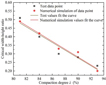
It can be seen from Table 5 that both the test and simulated values of the critical width-height ratio of finite soil decrease with the increase of the compaction degree of the fill. The test value of the critical width-height ratio is close to the simulated value under the same compaction degree, and the maximum difference between the test and simulated values of the critical width-height ratio of finite soil is not more than 15 %. By data analysis software origin based on nonlinear least square method, the test and simulation values are fitted respectively; the relationship curve between critical width-height ratio and compaction degree as shown in Fig. 13. The corresponding fitting equations are shown in Eq. (3) and Eq. (4):
As can be seen from Eq. (3) and Eq. (4), both the test and simulated values of the critical width-height ratio decreased linearly with the increase of the compaction degree of the fill, and the fitting coefficients of Eq. (3) and Eq. (4) was 0.907 and 0.962, respectively, showing a high linear correlation.
5. Conclusions
In term of the sandy soil of East Dongting Lake, the active failure of the fill with different compaction degrees and different width-height ratios under RB mode is studied by model test and numerical simulation. The main conclusions are as follows:
1) The development process of the active fracture surface of fill under RB mode is top-down sliding layer by layer, and its formation mechanism is similar to that of push landslide; that is, the upper soil first deforms, and then the lower soil is pushed and squeezed to make it deform and slide successively.
2) Under RB mode, the active fracture surface of fill is an inclined plane that does not pass the heel of the wall, and there are often several fracture planes close to parallel in the fractured body. The fracture surface of the finite soil is between the movable retaining wall and the fixed retaining wall, and the plane shape of the fracture body is “trapezoid”. The active fracture surface of semi-infinite soil is between the movable retaining wall and the soil surface, and the plane shape of the fracture body is “triangle”.
3) For loose (81 %) finite soil, when the width-height ratio of fill is constant, with the increase of compaction degree, the upper point of the active fracture surface under RB mode gradually moves up from the fixed retaining wall to the soil surface, the fracture surface gradually becomes steeper, the volume of the fractured body gradually decreases, the plane shape of the fractured body changes from “trapezoid” to “triangle”, and the finite soil body changes to semi-infinite soil. It is proved that the compaction degree is an important factor affecting the critical width-height ratio of finite soil.
4) For loose (81 %) semi-infinite soil, when the width-height ratio is constant, with the increase of compaction degree, the active fracture surface gradually becomes steeper and the volume of the fractured body gradually decreases under RB mode, but the soil between the two walls is still semi-infinite.
5) Under RB mode, the critical width-height ratio of finite soil decreases linearly with the increase of compaction degree. By fitting, the empirical equation of critical width-height ratio test value and simulation value considering the compaction degree are obtained: , . In the filling of highway embankment and foundation pit excavation of adjacent building, the critical width-height ratio of soil failure can be well calculated by obtaining soil compaction degree.
However, the result presented in this study is particularly for the critical width-height ratio of finite soil behind retaining wall considering the compaction degree of fill under RB mode. Further research is necessary for more general applications. For example, the various soil types, different displacement modes, active limit state and passive limit state of retaining wall should be taken into account. Plaxis2D is the finite element software, the discrete element software such as PFC2D, PFC3D, UDEC and 3DEC can be used to better simulate the test results.
References
-
Y. Que, J. Zhang, Y. Tian, and X. Li, “Spatial earth pressure analysis of clayey fill behind retaining wall in V-shaped gully terrain,” Soils and Foundations, Vol. 64, No. 6, p. 101538, Dec. 2024, https://doi.org/10.1016/j.sandf.2024.101538
-
K. Cui, W. Ci, and S. Yang, “DEM simulations of particle dissolution effects on the passive earth pressure of retaining walls,” Engineering Geology, Vol. 342, No. 1, p. 107742, Nov. 2024, https://doi.org/10.1016/j.enggeo.2024.107742
-
Y. Qi and S. Xiao, “Calculation method for static and seismic active earth pressure on counterweight retaining walls under translation based on two critical slip surfaces,” Transportation Geotechnics, Vol. 48, No. 1, p. 101349, Sep. 2024, https://doi.org/10.1016/j.trgeo.2024.101349
-
Y. Q. Zeng et al., “Sensitivity analysis of stability influencing factors for inverted t-type retaining wall in an active limit state based on strength reduction method and orthogonal experimental design,” IAENG International Journal of Applied Mathematics, Vol. 54, No. 11, pp. 2253–2265, 2024.
-
Y. Zeng, W. Hu, M. Chen, Y. Zhang, X. Liu, and X. Zhu, “Study on the failure characteristics of sliding surface and stability analysis of inverted t-type retaining wall in active limit state,” Plos One, Vol. 19, No. 2, p. e0298337, Feb. 2024, https://doi.org/10.1371/journal.pone.0298337
-
W. Hu, Y. Zeng, X. Zhu, and T. Hu, “Determination of passive earth pressure on a cantilever retaining wall in a narrow foundation pit based on logarithmic spiral sliding surface,” International Journal of Geomechanics, Vol. 23, No. 8, pp. 1–9, Aug. 2023, https://doi.org/10.1061/ijgnai.gmeng-8516
-
X. N. Zhu, Y. Q. Zeng, W. D. Hu, X. H. Liu, and X. Y. Zhou, “Experimental study on passive earth pressure against flexible retaining wall with drum deformation,” Engineering Letters, Vol. 29, No. 2, pp. 339–350, 2021.
-
X. N. Zhu, W. D. Hu, Y. Q. Zeng, T. Hu, S. Q. Jiang, and W. W. Wang, “Experimental study on deformation characteristics and active earth pressure against the flexible retaining wall with limited width soil in foundation pit,” IAENG International Journal of Applied Mathematics, Vol. 52, No. 4, pp. 875–889, 2022.
-
X. H. Liu, S. Q. Jiang, Y. Q. Zeng, W. D. Hu, Y. Gong, and J. L. Chen, “The plastic zone of clay under foundation load: an experimental and numerical analysis,” International Journal of Simulation Modelling, Vol. 22, No. 1, pp. 145–156, Mar. 2023, https://doi.org/10.2507/ijsimm22-1-co3
-
C. Xiong et al., “Active earth pressure of narrow cohesionless backfill on balance weight retaining walls rotating about the bottom,” Structures, Vol. 67, No. 1, p. 107039, Sep. 2024, https://doi.org/10.1016/j.istruc.2024.107039
-
X. Guan, A. Fusco, S. K. Haigh, and G. S. Phani Madabhushi, “LEAP centrifuge tests on retaining walls at Cambridge University,” Soil Dynamics and Earthquake Engineering, Vol. 180, No. 1, p. 108610, May 2024, https://doi.org/10.1016/j.soildyn.2024.108610
-
C. Y. Wang, X. P. Liu, Z. H. Cao, X. Jiang, and J. Q. Zhang, “Experimental study on characteristics of active slip surface of limited width soil behind rigid wall,” (in Chinese), Rock and Soil Mechanics, Vol. 42, No. 11, pp. 2943–2952, 2021.
-
X. Jiang, “Experimental study of deformation and failure characteristics with limited width behind the retaining wall and numerical simulation,” (in Chinese), Changsha University of Science and Technology, 2018.
-
X. B. Dai, “Experimental study of active earth pressure of cohesionless soil with limited width behind the retaining wall and numerical simulation,” (in Chinese), Hunan University, 2016.
-
T. Fang, S. H. Sun, C. J. Xu, H. L. Wang, R. R. Yang, and N. Wang, “Earth pressure experimental study of limited soil considering the mode of displacement of retaining wall,” (in Chinese), Journal of Railway Science and Engineering, Vol. 16, No. 5, pp. 1178–1185, 2019.
-
M. Niedostatkiewicz, D. Lesniewska, and J. Tejchman, “Experimental analysis of shear zone patterns in cohesionless for earth pressure problems using particle image velocimetry,” Strain, Vol. 47, No. s2, pp. 218–231, Dec. 2011, https://doi.org/10.1111/j.1475-1305.2010.00761.x
-
M. Y. Xia, “Experimental Analysis on Mechanics characteristics of narrow backfill behide foundation pit diaphragm wall,” (in Chinese), Journal of Underground Space and Engineering, Vol. 18, No. 2, pp. 546–553, 2022.
-
H. Weidong, Z. Xinnian, L. Xiaohong, Z. Yongqing, and Z. Xiyu, “Active earth pressure against cantilever retaining wall adjacent to existing basement exterior wall,” International Journal of Geomechanics, Vol. 20, No. 11, Nov. 2020, https://doi.org/10.1061/(asce)gm.1943-5622.0001853
-
L. Xu, H.-B. Chen, F.-Q. Chen, Y.-J. Lin, and C. Lin, “An experimental study of the active failure mechanism of narrow backfills installed behind rigid retaining walls conducted using Geo-PIV,” Acta Geotechnica, Vol. 17, No. 9, pp. 4051–4068, Feb. 2022, https://doi.org/10.1007/s11440-021-01438-9
-
J. L. Chen, L. B. Yang, X. H. Liu, H. Chen, and S. Q. Jiang, “Experimental study on the influence of compaction degree of backfill behind wall on active sliding zone,” (in Chinese), Science and Technology and Innovation, No. 11, pp. 10–13, 2023.
-
H. Z. Zhang, C. J. Xu, S. B. He, Z. J. Huang, and X. H. He, “Study of active earth pressure of finite soils under different retaining wall movement modes based on discrete element method,” (in Chinese), Rock and Soil Mechanics, Vol. 43, No. 1, pp. 257–267, 2022.
-
H. Z. Zhang, C. J. Xu, L. J. Liang, S. L. Hou, R. D. Fan, and G. H. Feng, “Discrete element simulation and theoretical study of active earth pressure against rigid retaining walls under RB mode for finite soils,” (in Chinese), Rock and Soil Mechanics, Vol. 42, No. 10, pp. 2895–2907, 2021.
-
H. Z. Zhang, “Study on active earth pressure of finite soils under different retaining wall movement modes,” (in Chinese), Zhejiang University, 2022.
-
D. Liu, “DEM analysis and simplified calculation of active earth pressure on retaining walls of narrow backfill width,” (in Chinese), Hunan University, 2018.
-
L. Wan, X. Z. Zhang, Y. F. Wang, L. M. Xu, and C. J. Xu, “DEM study on active failure and earth pressure of cohesionless soil with limited width behide retaining wall,” (in Chinese), Journal of Civil and Environmental Engineering, Vol. 41, No. 3, pp. 19–26, 2019.
-
D. Huang, “Study on active earth pressure on retaining walls adjacent to existing basement,” (in Chinese), Zhejiang University, 2010.
-
Q. Y. Zeng and J. Zhou, “Analysis of passive earth pressure due to various wall movement by particle flow code (2D),” (in Chinese), Rock and Soil Mechanics, Vol. 26, pp. 43–47, 2005.
-
Y.-J. Lin, F.-Q. Chen, J.-T. Yang, and D. Li, “Active earth pressure of narrow cohesionless backfill on inclined rigid retaining walls rotating about the bottom,” International Journal of Geomechanics, Vol. 20, No. 7, pp. 1–11, Jul. 2020, https://doi.org/10.1061/(asce)gm.1943-5622.0001727
-
N. Benmebarek, H. Labdi, and S. Benmebarek, “A numerical study of the active earth pressure on a rigid retaining wall for various modes of movements,” Soil Mechanics and Foundation Engineering, Vol. 53, No. 1, pp. 39–45, Apr. 2016, https://doi.org/10.1007/s11204-016-9362-z
-
K. Huang, R. Liu, Y. Sun, L. Li, Y. Xie, and X. Peng, “Study on the calculation method of active earth pressure and critical width for finite soil behind the retaining wall,” Frontiers in Earth Science, Vol. 10, No. 1, pp. 1–9, May 2022, https://doi.org/10.3389/feart.2022.883668
-
Z. Lin et al., “Analytical solution for displacement-dependent active earth pressure considering the stiffness of cantilever retaining structure in cohesionless soil,” Computers and Geotechnics, Vol. 170, No. 1, p. 106258, Jun. 2024, https://doi.org/10.1016/j.compgeo.2024.106258
-
J.-Y. Liu and J. Liu, “Seismic active earth pressure in nonhomogeneous and anisotropic soils,” Computers and Geotechnics, Vol. 170, No. 1, p. 106315, Jun. 2024, https://doi.org/10.1016/j.compgeo.2024.106315
-
C. Xiong et al., “Study on active earth pressure of narrow backfill of balance weight retaining wall under translational displacement mode,” Developments in the Built Environment, Vol. 18, No. 1, p. 100430, Apr. 2024, https://doi.org/10.1016/j.dibe.2024.100430
About this article
The study was supported by the Natural Science Foundation of Hunan Province of China (Grant No. 2022JJ40160), the Key Scientific Program of Hunan Education Department, China (Grant No. 22A0472), and the Postgraduate Scientific Research Innovation Project of Hunan Province, China (Grant No. CX20231231).
The datasets generated during and/or analyzed during the current study are available from the corresponding author on reasonable request.
Xiaohong Liu and Yongqing Zeng contributed to Conceptualization, Data Curation, Data Analysis and wrote the Original Draft Preparation of the study. Yuxin Wang and Yasi Ye contributed significantly to Funding Acquisition, Investigation and Methodology. Yuchen Liu and Haixing Cai helped perform Review and Editing with constructive discussions.
The authors declare that they have no conflict of interest.
