Abstract
The hub bearing with face spline transmission is a new type of hub bearing. The design method and standards are lack. In this work, the geometric relationship of the tooth profile parameters and the meshing situation are derived for the hub bearing face spline. The outer diameter , number of teeth , and face tooth profile angle are key design parameters. The verification conditions for preload, extrusion stress, tooth root bending stress, and shear stress are established based on strength theory and assumption of uniform load distribution. To validate the design, a case study is conducted on the hub bearing face spline in a certain vehicle model, with theoretical calculation and simulation of stress by using Finite Element Method. The present FEM results compare well with those of the literature data. Finally, through the incorporation the torque strength and durability tests of the face spline, the reliability of the design theory in this work is confirmed. The results indicates that, the tooth tip fillet has a significant impact on the meshing area, the maximum principal stress near the tooth root is highest at the arc of the tooth root, proving that the selection of the dangerous section is appropriate. The work has value in promoting the development of automotive wheel hub bearings.
Highlights
- A meshing model for face spline pair was established by deriving the geometric relationship of face tooth parameters. The tooth tip fillet r1 has a significant impact on the meshing area and is optimized to the top cutting height C.
- Based on strength theory and assumption of uniform load distribution, the strength verification conditions for the extrusion stress, bending stress, and shear stress of the face spline were provided. Proposed a design flow with D, d, Z, φ as the main parameter.
- The current Mises stress obtained from the FEM model are compared with the published data with a 1.5% difference The maximum principal stress near the tooth root is highest at the arc of the tooth root, proving that the selection of the dangerous section is appropriate.
- Through simulation analysis, strength testing and durability performance testing, verified the reliability of the design method of face spline hub bearings provided in this paper.
1. Introduction
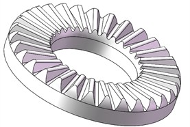
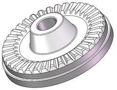
Hub bearings are one of the important safety components in the automotive chassis systems, and third-generation hub bearings are the mainstream in the market. In the power transmission system, the third-generation hub bearings transmit power through axial splines on the inner flange holes (Fig. 1(a)). In recent years, FAG (Schaeffler) in Germany has developed the hub bearings using the engagement of face spline (Fig. 1(b)). Splines are machined on the face of the hub bearing, so that the torque is transmitted through the connection of the face teeth meshing. The central long bolt is used to achieve locking with the ball cage end spline connection [1-2]. Compared with the hub bearings of axial spline, the weight of the transmission system when using the face spline can be reduced by 10 %, the capacity of torque carrying increases by more than 30 %. Besides that, problem of starting noise caused by axial splines that troubles the industry is solved by using the face spline, which has received more and more attention in the automotive transmission field.
However, in order to maintain technological leadership, manufacturers have not yet disclosed the design method and processing technology of the hub bearing face spline, therefore the relevant design standards are lack.
The GB/T 17855-2017 Calculation Method for Load Capacity of Splines specifies the calculation method for the load capacity of traditional axial splines [3]. The main parameters of the face spline teeth are described in JB/T 4316.1-2011 Straight End Gear Disc Part 1: Series Parameters and Dimensions, but there is no clear explanation on how to analyze the bearing capacity and strength verification of the face spline teeth [4]. Tian Maoquan [5] conducted research on the parameters and calculation methods of face teeth for aviation engines, and proposed corresponding strength verification methods. Huang Fa [6] investigated the design of circular end tooth structures and proposed a mountain shaped bottom design with a two-stage transition circular arc. Yang Fengchan [7] ignored the influence of pre tightening force and analyzed the design and verification of face tooth parameters for industrial couplings. Li Wujun [8] and Tang Jinyuan [9] used analytical calculation and finite element method to verify the strength of the face teeth. The results showed that assuming uniform torque distribution, the analytical calculation results of bending stress were closer to the finite element method results. However, using uniform contact stress distribution assumption resulted in significant errors in verification.
Fig. 1Hub bearing with two types of spline
a) The axial spline
b) The face spline
The meshing of the face spline pair causes deformation, which corresponds to stiffness. The face spline teeth of wheel hub shaft bearing system can be viewed as a variable cross-section cantilever beam. A vibrations investigation for is successfully presented in Ref. [10], to obtain the influence of the beam widths, depths, and diameters on free vibrations by using the finite element method. Pany [11] has obtained the fundamental frequency of a spring-hinged uniform cantilever beam, by establishing a theoretical model of a spring-hinged beam.
Shao Guangjun [12] studied the precise formula for calculating the face tooth profile and improved the approximate calculation problem of the root cone angle.
Kim [13] proposed a pre-tensioned face tooth dynamics analysis model based on GW contact model and three-dimensional solid element and investigated the effects of natural frequencies and stresses such as preload, tooth number, pressure angle, and half pitch.
Raviraj [14] investigated the influence of geometric parameters of face teeth on shear applications and contact stresses Jung [15] investigated the large-scale face gear transmission for precision indexing devices using finite element method and conducted ultimate load analysis. Zhang [16] analyzed the stress distribution on both sides of the double row face tooth meshing under simple pre tightening and working conditions. Liu Heng [17] conducted theoretical research on the positioning mechanism of circular arc end gear couplings, revealing the influence mechanism of tooth surface structural parameters on the centering effect. He proposed that the force on one side of the tooth surface along the radial component of the coupling should not be zero as a necessary condition for the tooth surface parameters to meet the centering requirements. Yang [18] analyzed the contact stiffness of face teeth based on the assumption of plane strain, considering the influence of structural details. By using the non-linear stiffness [19], the non-linear fundamental frequency of a cantilever beam is calculated by establishing a mechanical model.
The traditional machining of face teeth adopts milling or grinding technology, while the face teeth of hub bearings need to be obtained by cold swing rolling plastic forming. In the design, it is necessary to consider issues such as rivet head mold design and machining interference. There is no publicly available literature on the design and processing of face splines for hub bearings. This article refers to the national standard for axial splines and the tooth profile design and strength verification of face gear discs and considers the structure and processing characteristics of hub bearings. Different to the national standard for axial splines and face gear discs, this work considers the structure and processing characteristics of hub bearings, especially the influence of using rotary forging process to manufacture face teeth. Through theoretical derivation and experimental verification, the design method of face splines for hub bearings is obtained, providing a theoretical basis for the research and development of face spline wheel hub bearings.
2. Tooth profile design of hub bearing face teeth
2.1. Tooth profile parameter design
There are two types of tooth profiles for face gear transmission: straight teeth and circular teeth. Circular teeth were originally developed by Gleason Corporation in the United States, and have the advantages of high meshing accuracy, automatic centering, and large torque transmission. They have been widely used in high-speed and high-power transmission couplings such as airplanes and high-speed railway locomotives [20-21]. Under the same parameters and operating conditions, circular end teeth perform better than straight end teeth in terms of contact strength and bending strength. However, the face transmission of hub bearings does not belong to high-speed and heavy-duty scenarios. Considering the difficulty and cost of mold processing, using straight teeth is more advantageous.
Design the teeth as standard contracting teeth, where the tooth thickness contracts at a 90°/ angle along the centerline of the tooth thickness, and the tooth tip and root height directions contract at the same angle, i.e. the root cone angle and apex cone angle are the same. At this point, the tooth thickness of the face spline on the indexing surface is equal to the tooth groove width. The top clearance of the face spline adopts an equal clearance design.
A three dimensional model of face spline pair is shown in Fig. 2. The face spline has three basic parameters: outer diameter , number of teeth , and face tooth profile angle . The larger the outer diameter , the stronger the load-bearing capacity, and the outer diameter is limited by the size of the bearing inner ring and the overall space. The larger the number of teeth , the smaller the tooth height and thickness, which is more favorable for the subsequent rolling forming of the face teeth, but the bending strength of a single tooth decreases. A larger profile angle of face spline is beneficial for the bending strength of the tooth root, and easier to meshing, but the larger the pre-tightening force required to prevent loose meshing, which increases the requirements for the performance of the locking bolt. Generally, the profile angle of face spline is between 40° and 60°, which is greater than that of axial spline [5].
Fig. 2Face spline pair of hub bearing
a) Driven tooth (axle bearing side)
b) Drive tooth (ball cage side)
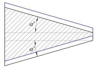
Different from the tooth profile angle of the face, attention should be paid to the profile angle during design. is evaluated in the plane perpendicular to the tooth bottom line, and is evaluated in the plane perpendicular to the dividing plane, as shown in Fig. 3, . In the milling process of rivet head molds, the profile angle is directly related to the tool angle, and this angle should be noted during 3D modeling. The main parameters are calculated as follows.
Fig. 3Geometric relationship of tooth profile
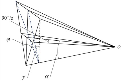
Where the root cone angle [5]:
Large end indexing surface chord tooth thickness :
Big end theory full tooth height:
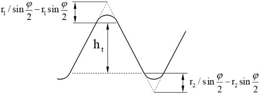
Effective meshing tooth height at the middle of the tooth width in Fig. 4:
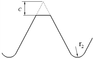
where and are the fillet radius at the tooth tip and root, respectively. To avoid meshing interference, is generally taken as 1.201.5, affecting the top clearance, root stress concentration, and actual meshing area. The calculation of small end tooth profile parameters is similar to that of large end, and will not be repeated here.
Fig. 4Face tooth profile parameters
2.2. Analysis of meshing area
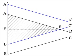
As shown in Fig. 5, assuming the tooth flank is trapezoidal ABCD and the other tooth flank meshing with it is trapezoidal , due to the presence of top clearance, , the two tooth flanks cannot completely overlap, and the actual contact area may be triangular or trapezoidal.
Fig. 5Face spline contact zone
a) The contact surface is triangular
b) The contact surface is trapezoidal
Where in the triangle :
At the critical state, , which can be:
which is simplified as:
This formula is independent of , that is, when , the contact area is triangular, and when is less than this critical value, the contact area is trapezoidal. The area of triangle :
As shown in Fig. 5(b), there is a geometric relationship:
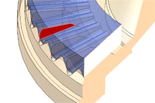
The correctness of the above analysis can be verified in the 3D assembly model, as shown in Fig. 6, where the black area represents the actual meshing area. The contact area when 0.8 mm is greater than the contact area when 0.9 mm.
Fig. 6Face splines coupling with equal top clearance
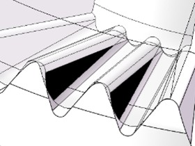
a)0.9, 0.6
b) 0.8, 0.6
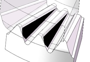
Fig. 7Detail design optimization of face splines
a) Drive tooth top cutting
b) Reduction of drive spline tooth width
Although the design in Fig. 6(b) has a larger meshing contact area, the contact stress generated near the center meshing is too high, due to the thinner tooth thickness and lower stiffness at the small diameter. To improve the contact stress at the central meshing point, the small diameter of the driving teeth can be increased by 3-5 mm, that is, the width of the driving teeth can be reduced while the driven teeth remain unchanged. This change is also beneficial in avoiding interference between the rivet head and the work piece during teeth rotary forging process. In addition, the drive tooth tip can be designed as a flat top to reduce the rotary forging force. To avoid meshing interference, the cutting height should be greater than the fillet radius of the tooth root, shown in Fig. 7(a). After these optimizations, the meshing contact area is shown in Fig. 7(b) which is slightly smaller than the aforementioned triangle. The contact area can be calculated according to the above method, but at the same time, the average torque acting diameter increases and the single tooth force decreases.
3. Stress calculation and strength verification of the two end spline
The hub bearing face spline mainly bears torque, and also bears a certain axial tightening load to ensure the correct meshing of the spline pair.
3.1. Determination of pre tightening force for face splines
To prevent tooth disengagement during the operation of the spline pair, the spline pair needs to be locked axially with bolts, and the spline is subjected to the combined action of torque T and axial preload force . Analyze the force acting on a single tooth, assuming that the normal forces acting on the two tooth surfaces are and , respectively.
Fig. 8Mechanics analysis of face splines meshing
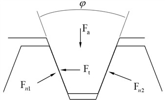
As shown in Fig. 8, there is an equilibrium equation:
Can be obtained:
In order to ensure that the meshing spline pair does not disengage and the front and rear tooth surfaces always maintain contact during operation, it is necessary to ensure that the rear tooth surface is subjected to force, that is:
3.2. Verification of tooth surface extrusion stress
Bearing side tooth surface compression stress [3]:
where is the actual meshing contact area, which can be accurately calculated using the aforementioned method. , is the material safety factor, taken as 1.25. is the comprehensive influence coefficient, which includes the influence of multiple factors. Referring to GB/T 17855-2017 and the design of gear transmission, for the hub bearing face spline, its transmission is relatively stable, and the working condition coefficient is taken as 1.1. The tooth flank clearance coefficient is used to consider the uneven load distribution caused by tooth flank clearance. As the hub bearing face spline is designed for seamless fit and the compressive axial force is small, is taken as 1. The distribution coefficient is taken as 1.2 to consider the uneven load distribution between teeth due to accumulated tooth pitch error. The axial offset load coefficient is taken as 1.1 to consider the tooth direction error, coaxiality error, and uneven load along the tooth direction caused by torsional deformation after loading. In addition, due to the rotary forging process, there are rounded edges on the inner and outer diameters of the spline, and the large end is prone to insufficient metal filling, which results in the actual meshing area being smaller than the theoretical value. Therefore, the meshing area coefficient is introduced, where actual meshing area/theoretical meshing area. After tooth profile mapping and 3D model simulation, 0.95 is taken. Therefore: 1.53.
3.3. Root bending stress verification
The starting point of the tooth root arc is taken as the hazardous section, and the torque and preload force are considered as uniformly distributed loads acting on the meshing tooth surface, as shown in Fig. 9. The middle of the tooth width is analyzed.
Fig. 9Hazardous section of the face splines
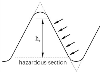
Where the load density :
The bending moment experienced is:
Therefore, the stress intensity conditions for tooth root bending are cited from [3] as below:
Among them, is the safety factor, taken as 1.25, and the dangerous section tooth thickness corresponding to the middle of the tooth width:
3.4. Shear stress verification
Shear stress is mainly generated by torque, ignoring the influence of preload force. Its verification conditions are [3]:
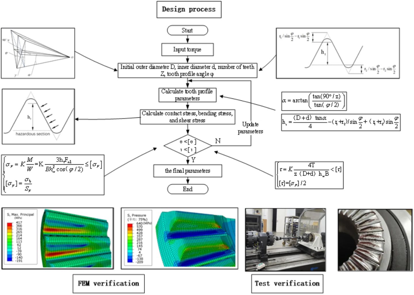
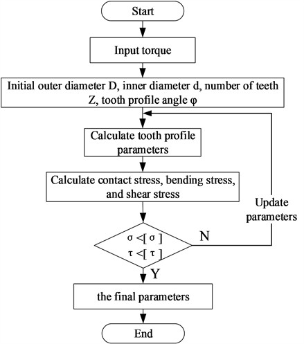
Overall, the design process can be summarized as shown in Fig. 10. Based on the requirements of the vehicle transmission torque, combined with the overall design of the bearing, the initial straight outer diameter , inner diameter , number of teeth , and face tooth profile angle are determined. Calculate tooth profile parameters such as tooth height and width, as well as meshing area analysis, and then conduct force analysis to verify tooth root bending stress, tooth surface extrusion stress, and shear stress. If the verification results do not meet the requirements, priority should be given to increasing the outer diameter for redesign, determining the final tooth profile parameters, and finally conducting product performance testing.
Fig. 10Flow chart of design and verification
4. Design examples
A certain new energy sedan requires the maximum torque transmitted by the hub bearing face spline to be 4200 N·m. According to the overall design and installation requirements of the bearing, the outer diameter of the face spline should be between 62-66 mm, the inner diameter should be within the range of 36-40 mm, and the spline material should be S55C quenched and tempered. Based on the aforementioned design principles, the face spline design has been completed and the results are listed in Tables 1-3. The design meets the strength requirements.
Table 1Design values of face spline
Name | Symbol | Design value |
Input torque | (N·m) | 4200 |
Large end outer diameter | (mm) | 64 |
Small end inner diameter | (mm) | 38 |
Number of teeth | 37 | |
face tooth profile angle | (°) | 55 |
Tooth tip circle radius | (mm) | 0.9 |
Root circle radius | (mm) | 0.7 |
Root cone angle | (°) | 4.67 |
Profile angle | (°) | 55.16 |
Large end indexing surface chord tooth thickness | (mm) | 2.716 |
Effective outer diameter of drive teeth | (mm) | 62 |
Effective small diameter of drive teeth | (mm) | 48 |
Drive tooth top cutting height | (mm) | 1.6 |
Table 2Materials property and comprehensive coefficients
Name | Symbol | Design value |
Tensile strength | (MPa) | 960 |
Yield strength | (MPa) | 650 |
Material safety factor | 1.25 | |
Allowable bending stress | (MPa) | 768 |
Permitted pressure application | (MPa) | 520 |
Permissible shear stress | (MPa) | 384 |
Comprehensive coefficient | 1.53 |
Table 3Strength verification results according to design values
Name | Symbol | Verification value |
Required axial total locking force | (N) | 79721 |
Normal pressure on a single tooth surface | (N) | 4656 |
Effective tooth height in the middle of the tooth width | (mm) | 1.435 |
Equivalent tooth thickness of dangerous section | (mm) | 3.086 |
Dangerous section bending moment | (N·mm) | 2945.7 |
Bending section coefficient | (mm3) | 11.11 |
Tooth root bending stress | (MPa) | 515.3 |
Tooth surface compressive stress | (MPa) | 473.5 |
Root shear stress | (MPa) | 169.6 |
5. Simulation analysis
Based on the above tooth profile parameters, a three dimensional FE model based on ABAQUS software is established as shown in Fig. 11. Considering the calculation cost, three teeth are selected for static analysis. By material tensile test, the elastic modulus of S55C is 203GPa, with a Poisson’s ratio of 0.298, the stress-strain curve is shown in Fig. 12. Establish a coupling point at the center of rotation, and couple the meshing surface to the center of coupling point. Material tensile test Two analysis steps were set up, the first step involves applying a small preload force to establish stable contact, and the second step involves applying a normal preload and torque, and nonlinear analysis were selected in the steps. To facilitate convergence, a linear increase of torque is applied in the second step.
The contact area is set to face-to-face contact with a friction coefficient of 0.15. The contact algorithm adopts the penalty function method. Sliding formulation adopts finite sliding.
Using hexahedral elements, the mesh of the tooth shaped part is refined, with a side length of 0.3 mm and a total of 44279 elements, which can ensure the accuracy and reliability of the simulation. The bottom surface of the driven teeth is set with completely fixed constraints, and the driving teeth release the degrees of freedom to rotate and move around their axis. The convergence criteria are set by software default.
Fig. 11Finite element model
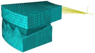
Fig. 12Stress-strain curve of S55C
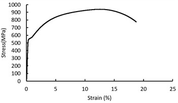
Fig. 13 shows the distribution of contact pressure. due to the lack of rounded edges at the top of the drive teeth, there is a phenomenon of stress concentration, results in a maximum pressure of 640/460 MPa for drive and driven tooth respectively , the average pressure in contact zone are 167/158 MPa respectively, the pressure lower than the allowable compressive stress [] of material, which meets the design requirements.
Fig. 13Contact pressure (MPa) contour
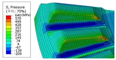
a) Drive tooth
b) Driven tooth
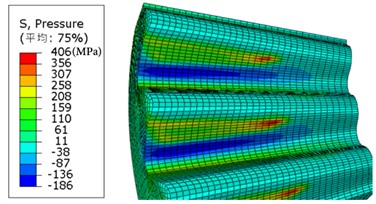
Fig. 14 shows the result of maximum principal stress. The maximum principal stress near the tooth root is highest at the arc of the tooth root, indicating that the selection of the dangerous section mentioned above is appropriate. The maximum stress of the driving tooth is 450 MPa, and the maximum stress of the driven tooth is 417 MPa, less than the allowable bending stress of the material. Compared with the calculated value of bending stress (515.3 MPa, shown in Table 3), the maximum difference is 19 %, the difference is mainly due to the comprehensive influence coefficient (as described in Section 2.2) in theoretical calculations, so the simulated value is less than the calculated value.
Also, the von-Mises stress contour of driven and drive tooth can be obtained an shown in Fig. 15, the maximum Mises-stress are 670 MPa\572 MPa for drive and driven tooth respectively, which are below the tensile strength of the material.
The FEM results in this work are compared with those of Zhang [16] and Kim [13] as shown in Table 4. The comparison shows that the present (face spline) results are closer to those of Kim [13] than Zhang [16].
Fig. 14Maximum principal stress (MPa) contour
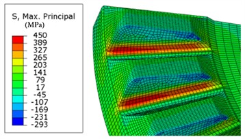
a) Drive tooth
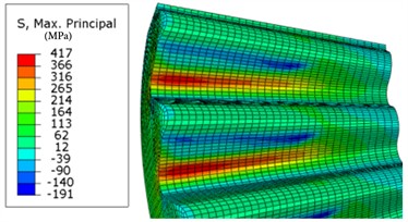
b) Driven tooth
Fig. 15Von-Mises stress (MPa) contour
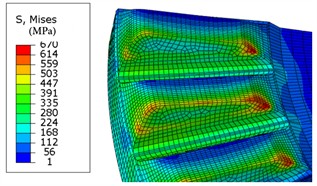
a) Drive tooth
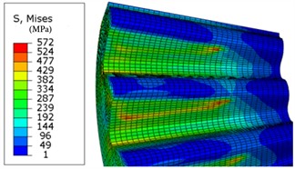
b) Driven tooth
Table 4Comparison of FEM results with literature data
Mises stress (MPa) | Difference (%) | |
Figure 15 and 14 in this work | 572 | |
Figure 21 in Kim [13] | 563 | 1.5 |
Figure 8 in Zhang [16] | 728 | 27 |
6. Experimental verification
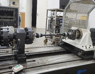
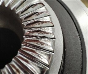
Based on the above design, manufacture face spline hub bearing samples, conduct spline torsional strength testing and durability performance testing. Using a spline strength and durability testing machine, as shown in Fig. 16, the torsional strength testing conditions are: apply torque at a rate of 245N·m/s until the spline fractures. Experimental results: at 8703 N·m, the tooth surface suffered compression failure, as shown in Fig. 17, exceeding the design requirements 4200 N·m and having high design redundancy ,indicating that the product strength is sufficient.
Fig. 16Experimental setup
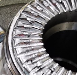
Conduct a spline durability test under accelerated durability test conditions (sine wave loading, peak value of 1800 N·m, valley value of 600 N·m, frequency of 3 Hz). The results showed that after 100000 cycles, there was no significant wear or damage on the tooth surface. However, after 400000 cycles, there were wear on the teeth sides, but it can mesh and drive normally, as shown in Fig. 18. The fatigue test meets the design requirements.
In addition, after testing, the overall static strength, stiffness, durability and other performance of the face spline hub bearing product meet the design requirements.
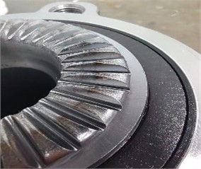
Fig. 17Teeth after torque test
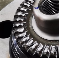
a) Driving teeth break
b) Driven teeth break
Fig. 18Teeth surface after durability test
a) 100000 cycles
b) 400000 cycles
7. Conclusions
Compared with other generation wheel hub bearings, face spline wheel hub bearings can transmit greater torque and are more suitable for high torque applications such as electric vehicles. They have great potential for application in the new energy vehicle industry. This work systematically elaborates on the design of hub bearing face spline transmission, laying the foundation for the application of hub bearing face splines in the automotive industry. The results indicates that:
1) A meshing model for face spline pair was established by deriving the geometric relationship of face tooth parameters. The tooth tip fillet has a significant impact on the meshing area and is optimized to the top cutting height .
2) Based on strength theory and assumption of uniform load distribution, the strength verification conditions for the extrusion stress, bending stress, and shear stress of the face spline were provided. Proposed a design flow with , , , as the main parameter.
3) The current Mises stress obtained from the FEM model are compared with the published data with a 1.5 % difference The maximum principal stress near the tooth root is highest at the arc of the tooth root, proving that the selection of the dangerous section is appropriate.
4)Through simulation analysis, strength testing and durability performance testing, verified the reliability of the design method of face spline hub bearings provided in this paper.
In the future, the author will study the manufacturing process of face spline hub bearing to further optimize the design.
References
-
R. Langer et al., “Wheel bearing arrangement with face spline,” US7806597B2, 2010.
-
R. Langer et al., “Face spline for driven wheel hub,” US8444322B2, 2013.
-
“Calculation method for spline bearing capacity,” Standardization Administration of China, GB/T 17855-2017, 2017.
-
“Straight toothed discs – Part 1: Series parameters and dimensions,” Ministry of Industry and Information Technology of the P.R.C, JB/T 4316.1-2011, 2011.
-
M. Tian, “Research on the parameter design and calculation method of face spline tooth,” (in Chinese), in 4th China Aerospace Society Youth Science and Technology Forum, Vol. 2010, pp. 714–721, 2010.
-
F. Huan, “Research on the design method of circular end tooth structure,” (in Chinese), Nanjing University of Aeronautics and Astronautics, 2013.
-
F. Yang, S. Wu, Z. Lu, Lucily, and M. Li, “Parameter design and strength calculation of face teeth for industrial couplings,” (in Chinese), Heavy Machinery, Vol. 2020, No. 1, pp. 69–72002, 2020, https://doi.org/10.13551/j.cnki.zxjxqk.2020.01.015
-
W. Li, “Strength analysis of straight tooth curvic coupling and research on CNC grinding technology,” (in Chinese), Central South University, 2014.
-
J. Tang, D. Lei, and X. Liu, “Research on the design of straight toothed curvic coupling,” Mechanical Design, Vol. 30, No. 12, pp. 6–11, 2013, https://doi.org/10.13841/j.cnki.jxsj.2013.12.059
-
C. Pany, “Large amplitude free vibrations analysis of prismatic and non-prismatic different tapered cantilever beams,” Pamukkale University Journal of Engineering Sciences, Vol. 29, No. 4, pp. 370–376, Jan. 2023, https://doi.org/10.5505/pajes.2022.02489
-
C. Pany and G. V. Rao, “Large amplitude free vibrations of a uniform spring-hinged beam,” Journal of Sound and Vibration, Vol. 271, No. 3-5, pp. 1163–1169, Apr. 2004, https://doi.org/10.1016/s0022-460x(03)00572-8
-
G. Shao, G. Li, and W. Ruan, “Research on the tooth shape and forming processing of curvic coupling,” (in Chinese), Mechanical Transmission, Vol. 39, No. 11, 2015, https://doi.org/10.16578/j.issn.1004.2539.2015.11.040
-
B. J. Kim, J. Oh, and A. Palazzolo, “An improved preloaded Curvic coupling model for rotordynamic analyses,” Journal of Sound and Vibration, Vol. 544, p. 117391, Feb. 2023, https://doi.org/10.1016/j.jsv.2022.117391
-
M. Raviraj and M. V. Buddhe, “Design and analysis of geometrical parameters influencing on curvic coupling,” International Journal of Innovations in Engineering Research and Technology, Vol. 5, No. 5, pp. 1–5, 2018.
-
Y.-S. Jung, J.-C. Gao, G.-I. Lee, K.-R. Jung, and J.-Y. Kim, “Large curvic coupling gear for ultraprecision angle division using FEM,” International Journal of Precision Engineering and Manufacturing, Vol. 22, No. 3, pp. 495–503, Feb. 2021, https://doi.org/10.1007/s12541-020-00453-2
-
D. Zhang, C. Yang, T. He, J. Liu, and J. Hong, “Modelling and stress analysis for double-row curvic couplings,” Proceedings of the Institution of Mechanical Engineers, Part C: Journal of Mechanical Engineering Science, Vol. 235, No. 19, pp. 4231–4243, Nov. 2020, https://doi.org/10.1177/0954406220974051
-
H. Liu, J. Hong, and L. Li, “Positioning mechanism of curvic coupling,” (in Chinese), Journal of Propulsion Technology, Vol. 40, No. 6, pp. 1382–1388, 2019, https://doi.org/10.13675/j.cnki.tjjs.180176
-
C. Yang, D. Zhang, Y. Dou, and J. Hong, “Stiffness modelling for one curvic coupling considering contact details,” in Lecture Notes in Mechanical Engineering, Vol. 58, Singapore: Springer Nature Singapore, 2020, pp. 593–613, https://doi.org/10.1007/978-981-15-8049-9_37
-
C. Pany and G. V. Rao, “Calculation of non-linear fundamental frequency of a cantilever beam using non-linear stiffness,” Journal of Sound and Vibration, Vol. 256, No. 4, pp. 787–790, Sep. 2002, https://doi.org/10.1006/jsvi.2001.4224
-
Y. Li, “Study of the flexible coupling and arc tooth connection technology for the superpower locomotives,” (in Chinese), Southwest Jiaotong University, 2007.
-
H. Liu, J. Hong, and L. Li, “Progress and prospect of structural design and processing technology of curvic coupling,” (in Chinese), Journal of Propulsion Technology, Vol. 39, No. 4, pp. 721–730, 2018, https://doi.org/10.13675/j.cnki.tjjs.2018.04.001
About this article

The authors would like to thank Hubei Provincial Natural Science Foundation Project of China for the financial and technological support given to this study through the project “Micro motion wear mechanism and fatigue prediction of electric vehicle drive connections under complex operating conditions” (Grant numbers 2024AFD031).
The authors would like to thank the Key Project of Scientific Research Plan of Hubei Provincial Department of Education of China (Grant numbers D20232603).
The authors would like to thank the Xiangyang City Research and Development Project (Grant numbers 2022ABH006560).
Author Wei Xiong has received research support from Hubei New Torch Technology Co., Ltd.
The datasets generated during and/or analyzed during the current study are available from the corresponding author on reasonable request.
Wei Xiong: established the geometric relationship of the tooth profile parameters and the meshing situation. Zhong Di Deng: built the FEM contact model and calculated the contact pressure of the face spline. Jun Li: completed the theoretical verification of mechanical properties. You Wang: carried out the FEM simulation for extrusion stress, tooth root bending stress, and shear stress are established. Hai Bo Zhang: designed involute spline tooth profile. Song Mei: conducted spline torsional strength testing and durability performance testing.
The authors declare that they have no conflict of interest.
