Abstract
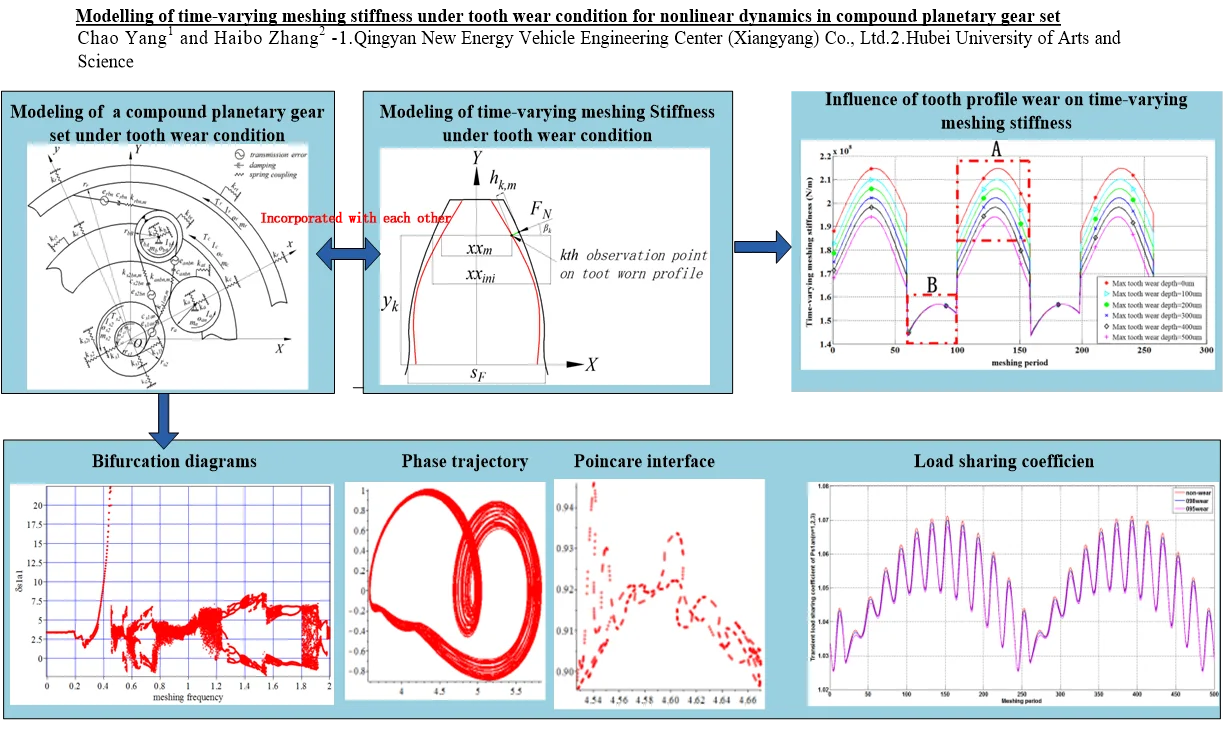
Under tooth profile wear condition, with running time increasing, the tooth chord length of the gear tooth is thinner and the tooth profile is not involute profile any more, which results in the changes in amplitude and fluctuation of time-varying meshing stiffness. In this work, in order to reveal the influence of tooth profile wear on time-varying meshing stiffness, an analytical model for calculating the time-varying meshing stiffness under tooth wear condition is built and incorporated with a “translational-rotational” dynamic model of compound planetary gear set. Poincare section, the phase trajectory and bifurcation diagram are employed for analysis of periodic and chaotic motion. The results indicate that, tooth wear accumulation result in the reduction in the amplitude of meshing stiffness at the meshing region of double-pair teeth, but makes no difference in meshing stiffness for the meshing region of single-pair teeth. In order to avoid the system being in Chaos motions, under large tooth wear condition, the input speed should be avoided away from 3700 r/min-6725 r/min, so as to keep the system in a stable periodic motion state.
Highlights
- In this work, in order to reveal the influence of tooth profile wear on time-varying meshing stiffness, an analytical model for calculating the time-varying meshing stiffness under tooth wear condition is built and incorporated with a “translational-rotational” dynamic model of compound planetary gear set.
- The results indicate that, tooth wear accumulation result in the reduction in the amplitude of meshing stiffness at the meshing region of double-pair teeth, but makes no difference in meshing stiffness for the meshing region of single-pair teeth.
- 3.In order to avoid the system being in Chaos motions, under large tooth wear condition, the input speed should be avoided away from 3700 r/min-6725 r/min, so as to keep the system in a stable periodic motion state.
1. Introduction
As a strongly nonlinear excitation in gear transmission, time-varying meshing stiffness is a periodic excitation and contributes greatly in the periodic response in gear transmissions. A little change in either amplitude or fluctuation in time-varying meshing stiffness could result in obvious difference in dynamic response, especially in complex gear transmission, such as compound planetary gear set.
1.1. Modeling of meshing stiffness
Considering tooth profile modification and tooth root crack, lots of literature described the modeling of meshing stiffness for spur gears, helical gears, bevel gears and so on. Considering the tooth deflections, but neglecting the hertzian deflections, Sanchez [1] evaluated the meshing stiffness of spur gear pairs at any point of the path of contact and approximated by an analytical model. Sun [2] developed a revised time-varying mesh stiffness model for of spur gear pairs, and investigated the impact of the tooth width and torque on mesh stiffness. Assuming that the extended tooth contact is ignored, Ma [3] and Parey [4] established an improved analytical method suitable for gear pairs with tip relief, to determine time-varying mesh stiffness for spur gears. Cui [5] incorporated a finite element model of the spur gear undergoing damaged failure with a simulation calculation program to calculate the time-varying meshing stiffness. By defining the effective thickness of the gear teeth with the occurrence of cracks, a cracked gear-tooth meshing stiffness calculation method is proposed by Cui [6]. Chaari [7] derived an analytical formulation of the time varying mesh stiffness for spur gear tooth crack. Chen [8, 9] proposed an analytical mesh stiffness calculation model for non-uniformly distributed tooth root crack along tooth width. By taking the TVMS obtained from the finite element (FE) method as a benchmark, Huangfu [10] obtained the correction coefficient of the gear foundation stiffness of cracked helical gear pairs by the optimization method. By using a combination of finite element method (FEM) and local contact analysis of elastic bodies, Chang and Chen [11-13] proposed a model for determining mesh stiffness of cylindrical gears. By comparing results with those obtained by using two-dimensional (2D) finite element (FE) models and specific benchmark software codes [14], Gu [15] gave the time-varying mesh stiffness function for ideal solid spur and helical gears. In order to introduced meshing stiffness into lumped-parameter model for gear transmission, Chen and Wang [16-19] introduced spring damping pair to describe the meshing stiffness.
According to the literature above, although lots of work is proceeding on modeling of time-varying meshing stiffness under the condition of tooth modifications and tooth crack for spur gear, helical gear, cylindrical gears, the modeling of the meshing stiffness under tooth profile wear condition is absent. In this work, an analytical model for calculating the time-varying meshing stiffness under tooth wear condition is proposed.
1.2. Impact of parameter on meshing stiffness
Certain literature focused on the effects of parameter excitation on meshing stiffness. By using three-dimensional boundary element analysis, Saryazdi [20] found that meshing stiffness reduces as crack propagated, but the amount of reduction depended on the position of the contact line and crack propagation path. Sanchez [21] investigated the influence of profile modifications on meshing stiffness, considering both the symmetric and asymmetric reliefs. Huangfu [22] discussed the effects of the tip relief and surface wear on the meshing and the dynamic characteristics. In this work, the impact of tooth profile wear on time-varying meshing stiffness is revealed by using analytical model for meshing stiffness and numerical method for calculation.
1.3. Impact of meshing stiffness on dynamics
Works on the impact of meshing stiffness on dynamic behavior have been proceeding on for gear transmission. Lin and Tordion [23, 24] identified analytically effects of mesh stiffness parameters, including stiffness variation amplitudes, mesh frequencies, contact ratios, and mesh phasing, on these instabilities in two-stage gear systems. Cui [25, 26] introduced a universal gear profile equation reference to the actual manufacturing process to calculate the meshing stiffness and revealed that, the double pulse was generated due to the residual stiffness. Hbaieb [27] listed results of plagiarism investigation on dynamic stability of a planetary gear train under the influence of variable meshing stiffness.
In this work, by incorporating the modeling of the time-varying meshing stiffness under tooth profile wear with a “lumped-parameter” dynamic model of compound planetary gear set, the influence of the meshing stiffness reduced by tooth wear on dynamic behavior of compound planetary gear is revealed, by incorporating analytical model of meshing stiffness and kinematic partial differential equations of compound planetary gear set.
1.4. Impact of tooth wear on dynamics
The influence of tooth profile wear on dynamics of gear transmission is also researched before. Zhang [28, 29] investigated the influence of backlash generated by tooth profile wear on dynamics of compound planetary gear set, and revealed the coupling relation between tooth wear accumulation and load sharing behavior in compound planetary gear set. By incorporating a torsional dynamic model with a surface wear model, Kahraman [30] also revealed the two-way relationship between nonlinear planetary gear dynamics and tooth surface wear. Shen [31] employed the potential energy method to calculate the mesh stiffness, and adopted the Archard’s wear equation to calculate the tooth profile wear, then demonstrated that the tooth wear can result in the reduction of the mesh stiffness [32]. In this work, the influence of time-varying stiffness reduced by tooth profile wear is investigated.
According to literature listed above, lots of work focused on modeling of meshing stiffness under the condition of tooth crack or modification, influence of meshing stiffness on dynamics and influence of wear on backlash. However, the modeling of meshing stiffness under the tooth wear condition is ignored, as well as the impact of meshing stiffness reduced by tooth wear on gear transmission.
1.5. Objectives and scope
In this work, “single point observation method” proposed by Flodin [33] is introduced to Weber-Vanaschck[34] model of meshing stiffness to predict the time-varying meshing stiffness along the tooth profile under tooth wear condition. By changing the tooth wear depth, the effects of tooth wear on time-varying meshing stiffness is revealed. Then, the analytical model of the time-varying meshing stiffness under tooth wear condition is introduced into a “translational-rotational” dynamic model [29, 35] of compound planetary gear set, so that the impact of meshing stiffness reduced by tooth wear accumulation is investigated by calculating the steady response.
2. Modeling of time-varying meshing stiffness under tooth wear condition
In order to reflect the influence of tooth profile wear on time-varying meshing stiffness, the Weber-Vanaschck [34] model is employed and incorporated with a static gear wear model proposed by Flodin and Andersson [33], to calculate the changing of meshing stiffness with time increasing.
Firstly, the wear depth distribution along tooth profile is given by Zhang [28] by using “single point observation method”, shown as below:
where subscript k represents the kth observation point along tooth profile. In this work, the amount of observation point NN is 500, which results in a good precision. Subscript m represents the driving gear running for m rounds. The literature [28, 29] gives the definition for other parameters in Eq. (1). hk,mdetermines the wear depth distribution along tooth profile.
2.1. An analytical model for meshing stiffness under tooth wear condition
In this chapter, two essential questions are discussed and revealed: one is the influence of tooth chord length reduced by tooth profile wear on time-varying meshing stiffness, the other is method of introducing the time-varying meshing stiffness under tooth wear condition into the lumped-parameter dynamic model of compound planetary gear set. The first question is revealed in the modeling of the time-varying meshing stiffness under tooth wear condition, shown in Fig. 1, where xx1,k,ini and xx1,k,m represent the tooth chord length at kth observation point under initial condition of non-wear and the condition after the driving gear running for m rounds respectively, and subscript ”1” represents the driving gear, which are calculated as:
Tooth chord length after first iteration for wear calculation:
Tooth chord length after first iteration for wear calculation:
Fig. 1Modeling of time-varying meshing stiffness under tooth wear condition
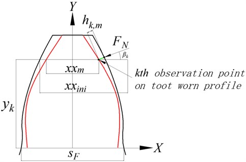
Based on assumption that the wear condition of different teeth is same, the gear wear in Fig. 1 is bilaterally symmetrical, and the gear wear in Fig. 1 is similar to the actual wear in planetary gears by Kahraman [30]. Where in Eq. (2), h1,k,1⋅sinβ1,k is the projection length of tooth wear depth from the kth observation point after one wear iteration, on the driving gear. h1,k,1 is given in Eq. (1), and β1,k and β2,k is derived in Fig. 2. The beta parameters in Fig. 2 is defined in literature [28], which is described above the Eq. (1).
Fig. 2Diagram of tooth profile
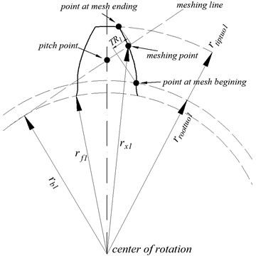
Where in Fig. 2, r1f is the dedendum radius of driving gear, r1b is the radius of base circle, r1,k is the distance between meshing point and center of rotation. When a pair of mating gears begins to mesh, the driving gear comes into engagement on the point at mesh beginning, shown in Fig. 2. The radius of the point at mesh beginning is r1toottuo. When the driving gear begins to separate from the driven gear on the point at mesh ending, the radius of the point at mesh ending is r1tiptuo. One meshing section is the section between the point at mesh beginning and meshing ending on the tooth profile. TR is the projection length of the meshing section from tooth profile on meshing line, and is divided into 500 equal pieces to set the observation point for tooth profile wear. The calculation for r1tiptuo,r1toottuoand TR1 is given as below:
Due to nonuniform distribution of the tooth wear depth along tooth profile, in the mesh section, the wear depth h1,k,m at kth observation point changes with the position of observation point and tooth wear iteration. In order to reveal the influence of tooth profile wear on meshing stiffness, the tooth chord length under tooth wear condition is given as below:
where in Eqs. (8-10), α1,k is the pressure angle of meshing point, or the kth observation point on the driving gear, β1,k is the angle between contact force FN and horizontal direction for meshing point. By introducing Eqs. (10-11) into Eqs. (2-3), the tooth chord length at kth observation point after the driving gear running for m rounds is calculated. In order to calculate the elastic deformation at meshing point, the tooth chord length of driving gear at dedendum s1f and the distance between the meshing point and horizontal line y1,k is given as below:
After the driving gear running for m rounds and tooth profile wear accumulation, the meshing deflection consists of tooth deflection δ1R,k,m and matrix deformation δ1Z,k from driving gear, tooth deflection δ2R,k,m and matrix deformation δ2Z,k from driven gear, as well as local contact deformation δPW,k:
where in Eqs. (15) and (17), due to tooth profile wear accumulation, the tooth chord length of driving gear xx1,k,iniand driven gear xx2,k,ini decreases to xx1,k,m and xx2,k,mrespectively, which results in a larger deformation for the tooth deflection of mating gears. Then, the local contact deformation is calculated as below:
where in Eq. (18), yh1,k is the distance between meshing point and the pitch point on driving gear, and is calculated in Eq. (19). In consideration of difficulty in convergence of numerical method, yh1,k not changes with tooth wear accumulation, as well as the equivalent radius of curvature ρ*k for the kth observation point. The time varying meshing stiffness Kk,m is calculated as below, and represents the meshing stiffness for the mating gears at the kth observation point after the driving gear running for m rounds:
2.2. Influence of tooth profile wear on time-varying meshing stiffness
In this work, in order to investigate the impact of tooth wear on meshing stiffness, a group of parameters from Eqs. (1-22) is assigned in Table 1-2. Influence of tooth profile wear on time-varying meshing stiffness is given as below in Fig. 3. The tooth chord length under tooth wear condition in Fig. 3 is calculated by Eqs. (1-3). By Eqs. (4-17), the time-varying meshing stiffness under the worn tooth chord length after the driving gear running for rounds is calculated by numerical method and displayed in Fig. 3.
As shown in Fig. 3, for the meshing pair formed by a pair of parallel shaft gears, the variation of the variable meshing stiffness in a meshing period varies with tooth profile wear. With the increase of number of revolutions of driving gear, the increasing in gear profile wear reduces the meshing stiffness amplitude of the meshing pair in the meshing region of double teeth meshing region where in Fig. 3 is labeled as “A”, and has little influence on the stiffness fluctuation of single tooth meshing region, where in Fig. 3 is labeled as “B”. It is indicated that, with the increasing in tooth profile wear, the meshing stiffness of double teeth decreases obviously, and both the stiffness amplitude and fluctuation in single tooth meshing region basically remains unchanged, leading to a decrease in the mean value of time-varying meshing stiffness.
Fig. 3Influence of tooth profile wear on time-varying meshing stiffness
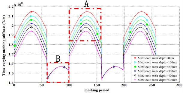
Table 1Symbols for modeling of meshing stiffness under tooth wear condition
Symbol | Units | Description |
NN | Total number of observation points, NN=500 | |
Pk | Pa | Contact pressure at the kth observation point |
Ft | N/m | Tangential force action on the surface |
αH | m | Hertz contact width |
ρ | m | Equivalent curve radius |
ρ1 | m | Curve radius of driving gear |
ρ2 | m | Curve radius of driven gear |
E | Pa | Equivalent modulus of elasticity |
Yk | m | Distance along line of action between pitch point and kth observation point |
vc | m/s | Speed at pitch circle |
w1w2 | rad/s | Angular speed of driving gear 1 and driven gear 2 |
vk | m/s | Sliding speed for observation point k |
u1u2 | Poisson’s ratio |
Table 2Parameters used in calculating meshing stiffness in Fig. 1
Parameters | Symbol and value |
Module | 0.004 m |
Pitch pressure angle | α= 20° |
Tooth width | B=0.04 m |
Center distance between driving gear and driven gear | 0.114 m |
Number of teeth for driving gear | zs1=36 |
Number of teeth for driven gear | za=21 |
Pitch diameter of driving gear | 0.144 m |
Pitch diameter of driven gear | 0.084 m |
dedendum diameter of driving gear | 0.152 m |
dedendum diameter of driven gear | 0.092 m |
Applied torque | T=2000 Nm |
angular velocity of driving gear | 5 rad/s |
Wear coefficient | K=5×10¹⁶m2/N |
Modulus of Elasticity | E=2.06×10¹¹Pa |
The main cause of this phenomenon is that, the tooth wear depth is higher near the addendum and dedendum than that near the pitch circle [33], resulting in smaller tooth chord length when the mating gears starts and exits meshing than when the mating gears runs in single tooth meshing region. In view of the difference on the tooth accumulation of double teeth and single teeth meshing region, the meshing stiffness of double teeth meshing region decreases with the accumulation of tooth profile wear, and the impact of tooth profile wear on meshing stiffness at single tooth meshing range is not obvious, so the meshing stiffness basically remain unchanged at region “B”. Generally speaking, the mean value of time-varying meshing stiffness decreases gradually with the accumulation of tooth profile wear, as well as the fluctuation peak of meshing stiffness.
2.3. Model for compound planetary gear set under tooth profile wear
In view that time meshing stiffness is a strongly nonlinear excitation in kinematical equation for gear transmission, especially for complex gear transmission, in this work, a lumped-parameter compound planetary dynamic model is employed and incorporated with the analytical model of meshing stiffness under tooth wear condition. The dynamic model of a compound planetary gear set under tooth wear condition is shown in Fig. 4.
Fig. 4Dynamic model of a compound planetary gear set under tooth wear condition
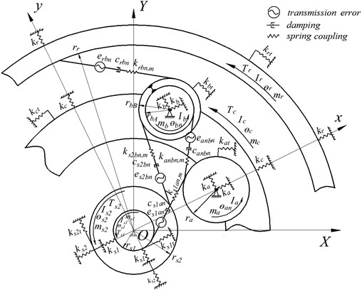
Known from the lumped-parameter dynamic model proposed by Zhang [36], in this work, the meshing stiffness of meshing pair Pj,m (j=s1an, s2bn, anbn, rbn) changes with the driving gear running for different rounds. The definition of other parameters in Fig. 4 is listed in Table 3.
Due to tooth profile wear increasing, the initial mean value of mesh stiffness (ks1anm,ini, ks2bnm,ini, kanbnm,ini, krbnm,ini) and coefficient of meshing stiffness fluctuation υj,ini decrease with the driving gear running for m rounds. By extracting the first harmonic of Fourier transform for the time-varying meshing stiffness after the driving gear running for m rounds in Fig. 3, mean value of mesh stiffness Kj,m (j=s1an, s2bn, anbn, rbn) and coefficient of meshing stiffness fluctuation υj,m is given as below. By incorporating Kj,m and υj,m with the dynamic model in Fig. 4, influence of meshing stiffness under tooth wear condition on dynamics of compound planetary gear set is investigated:
where ωmesh is meshing frequency, γs1a(n) is the relative meshing angle between mating gears. By increasing the number of revolution m of driving gear s1, the tooth profile wear is calculated by Eq. (1) and the time-varying meshing stiffness is calculated by Eqs. (1-22). Then the dynamic response in the steady state time domain is solved by fourth-order Runge Kutta method for kinematical Eqs. (24-29) of the compound planetary gear set.
Table 3Input parameters of the lumped parameter dynamic model
Input parameters | Symbol and value |
Number of carriers | c=1 |
Number of sun gears | s=2 (s1, s2) |
Number of rings | r=1 |
Module(mm) | m= 4 |
Number of teeth | zs1=36, zs2=48, za=21, zbA=18, zbB= 18, zr=84 |
Position angle of Planets | Ψan=2π(n-1)N Ψbn=2π(n-1)N+0.629 Ψs1an=Ψan-αs1a Ψs2bn=Ψbn-αs2b Ψrbn=Ψnb+αrb Ψanbn=1.478-αab-Ψan |
Pressure angles | αs1aαs2bαabαrb= 20° |
Initial mean value of mesh stiffness (N/m) | ks1anm,ini=1×10⁹ N/m ks2bnm,ini=1×10⁹ N/m Kanbnm,ini,=1×10⁹ N/m Krbnm,ini=1×10⁹ N/m, n=1, 2, 3 |
Initial coefficient of stiffness fluctuation υj,ini | υj,ini=0.25 |
Initial relative meshing phase | 0 |
Translational Bearing support stiffness (N/m) | ki(i=s1, s2, c, r, an, bn) = 1×10⁹N/m |
Torsional reaction stiffness (N/m) | krt=1×10⁹, others = 0 |
Mass (kg) | ms1=6.173, ms2=11.102, mr=5.038 mc=5,698, ma=1.997, mb=3.139 |
Mass moment of inertia (kg/m2) | Js1=0.016, Js2=0.052, Jr=0.152, Jc=0.08 Ja=0.0019, Jb=0.0022 |
Base circle of gear (mm) | rs1=67.65, rs2=90.21, ra=39.47, rbA=33.83 rbB=33.83, rr=15.79 |
Gear types | Spur |
Damping coefficient | ξ=0.07 |
Meshing frequency (Hz) | ωmesh=1 |
Initial static transmission error (μm) | Sun gear s1 has a 10 μm eccentricity error, others zero |
Initial backlash (μm) | Backlash of All meshing pairs bj=20, j=s1an, s2bn, anbn, rbn |
Applied load (Nm) | Ts1=2000 Nm, Ts2=969.69 Nm |
Central gear s1:
Planet gear an (n=1, 2, 3):
Planet gear bn (n=1, 2, 3):
Central gear s2:
Planet carrier c:
-rcbrca∑Nn=1ks2bn,mfs2bncos(αs2b)-rcbrca∑Nn=1cs2b˙δs2bncos(αs2b)
+rcbrca∑Nn=1krbn,mfrbncos(αrb)+rcbrca∑Nn=1cs2b˙δrbncos(αrb)
+rabrca∑Nn=1kanbn,mfabncos(αab)+rabrca∑Nn=1cab˙δabncos(αab)=0.
Ring r:
mr(¨yr+2ωc˙xr-ω2cyr)-∑Nn=1krbn,mfrbncosψrpn+kryr=0,
where fj(j=s1an, s2bn, anbn, rbn) represents the actual penetration depth after the theoretical penetration depth removing the initial backlash bj. kjfj is the meshing force of meshing pair Pj. Different from the kinematical equation equations in literature [29, 30], in this work, the impact of tooth wear on backlash is ignored. The impact of meshing stiffness under tooth wear condition is emphasised on in this dynamic model, and the description of each parameter in Eqs. (24-30) is listed below.
Table 4Description of the parameters in kinematics Eq. (23-28)
Notation | Unit | Description |
xi | mm | Translational vibration displacement for the part i under the coordinate system yOx rotated with carrier in x-direction |
yi | mm | Translational vibration displacement for the part i under the coordinate system yOx rotated with carrier in y-direction |
ωc | Rad/s | Angular speed of carrier c |
Ji | kg·m2 | The moment of inertia of component i |
θi | rad | Rotational vibration displacement for the part i under the ground coordinate system YOX |
rca | mm | Distance between center of carrier and planet gear a |
kj,m | N/m | Mean value of time-varying meshing stiffness for meshing pair Pj, after the system running for m time steps, j=s1an, anbn, rbn, s2bn, n=1, 2, 3 |
ki | N/m | Radial support stiffness of the part i |
kit | N/m | Tangential support stiffness of the part i |
δcanx,δcany | mm | Penetration displacement between carrier hole and planet an shaft, n=1, 2, 3 |
δcbnx,δcbny | mm | Penetration displacement between carrier hole and planet bn shaft, n=1, 2, 3 |
ri | mm | Base circle radius of the part i |
fj | mm | Actual penetration depth of mating gears in meshing pair Pj, j=s1an, anbn, rbn, s2bn, n= 1, 2, 3 |
Ψj | rad | Angle between the line of action of Pj and the x-direction of the coordinate system yOx |
3. Influence of the meshing stiffness reduced by tooth profile wear on nonlinear dynamics
3.1. Chaos and bifurcation
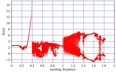
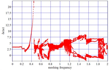
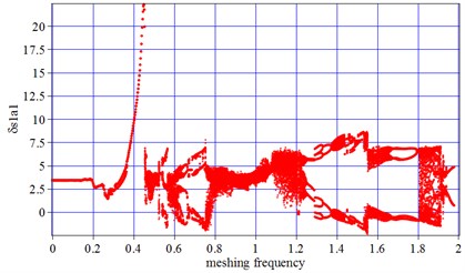
The fluctuation coefficient of meshing stiffness makes key roles in periodic motion of vibration, In order to investigate the influence of meshing stiffness under tooth wear condition on periodic vibration of compound planetary gear set, the diagram of Chaos and Bifurcation under different tooth wear condition is given as below. The max tooth wear depth usually appears on dedendum and addendum and is denoted as Wears1,max, which is calculated by Eq. (1) and is used to represent the running rounds of compound planetary gear set. Increasing of Wears1,max means the tooth wear increasing synchronously on other gears in compound planetary gear set.
Under non-wear condition, at low speed running section ωmesh=[0-0.4], the vibration amplitude at certain time point is identical to the ones at the time point of period-doubling, resulting in one point at the corresponding frequency at the section ωmesh=[0-0.4] in Fig. 5(a). With tooth wear increasing in Fig. 5(b), the one-cycle motion still remain primary, which indicates that low-frequency motion is stable after introducing the impact of tooth wear on time-varying meshing stiffness.
Fig. 5a) Bifurcation diagrams for non-wear; b) Bifurcation diagrams for a Wears1,max= 0.1 mm, c) Bifurcation diagrams for a Wears1,max= 1 mm. x-coordinate is non-dimonsional meshing frequency, y-coordinate is the non-dimonsional tooth deflection for meshing pair Ps1a1
a) Non-wear
b)Wears1,max= 0.1 mm
c)Wears1,max= 1 mm
With the running speed and meshing frequency continuing to increase, in the section ωmesh=[0.4-0.1.2], the vibration amplitudes at certain time point and its period-doubling, are no longer coincident and distributes discretely. Beside that, the negative value of vibration amplitude occurs at the section [0.6-0.8], which indicates double-tooth surface impact results from running speed increasing, as is shown in Fig. 5(a-c). In this frequency section, the vibration double period and quasi-period motion occupies a leading position, especially at the section ωmesh=[0.8-0.1.2], resulting from the influence of running speed increasing on transmission error. With tooth wear increasing, in Fig. 5(a-b), the number of double periods increase slightly at ωmesh=0.55, and vibration amplitude increases at ωmesh=0.68, which indicates that the tooth wear increasing and time-varying meshing stiffness decreasing cause a larger vibration amplitude. Although a larger amplitude occurs with tooth wear increasing, more regular quasi-periodic and double periodic motion presents, comparing non-wear Fig. 5(a) with tooth wear increasing in Fig. 5(b-c). It is indicated that, with the tooth profile wear increasing, the fluctuation coefficient of meshing stiffness decreasing cause a lower fluctuation of vibration and more regular vibration in periodic motion.
With the running speed and meshing frequency increasing to high frequency, in the section ωmesh=[1.2-2], Chaos motion occurs in Fig. 5(a). The introduction of tooth wear narrows the Chaos motions section from ωmesh=[1-1.3] to [1.1-1.2], as well as the scope of vibration amplitude.
The analysis results for Fig. 5 are able to be explained, by illustrating the influence of excitation frequency and meshing stiffness on shock in mesh and vibration. When the gear transmission runs in a low speed, the frequency of internal excitation is also low. Because the periodic motion of vibration is largely depended on time meshing stiffness, the introduction of tooth wear accumulation makes key roles on periodic motion at ωmesh=[0.4-1.2]. With the meshing frequency increasing, the influence of meshing stiffness decreasing due to tooth profile wear on periodic motion is less and less, compared with the impact of running speed and transmission error on vibration. So the decreasing meshing stiffness due to tooth wear accumulation has little affection on high frequency motion characteristics.
3.1.1. 3.2 The phase trajectory and Poincare interface
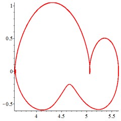
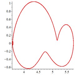
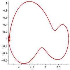
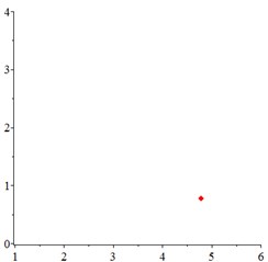
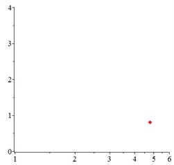
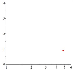
At the low frequency section ωmesh<0.4, in Fig. 6(a-c), for one observation point on meshing pair Ps1a1, the track of the vibration at different meshing period is presented as a closed curve. In order to confirm the cycle-index of the closed curve, at the Poincare interface Fig. 6(d-e), one-cycle periodic motion is seen clearly. With tooth wear accumulation, the vibration of one-cycle periodic motion continues, which indicates that the influence of meshing stiffness decreased by tooth wear accumulation is little. That may be explained that, one-cycle periodic motion leads at low running speed section.
Fig. 6At meshing frequency ωmesh= 0.35, the phase trajectory (a-c) and Poincare interface (d-f). x-coordinate is non-dimensional theoretical penetration depth of meshing pair Ps1a1, y-coordinate is non-dimensional theoretical penetration velocity of meshing pair Ps1a1
a) Non-wear
b)Wears1,max= 0.1 mm
c)Wears1,max= 1 mm
d) Non-wear
e)Wears1,max= 0.1 mm
f)Wears1,max= 1 mm
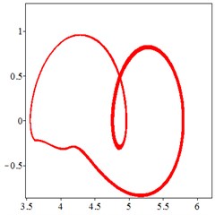
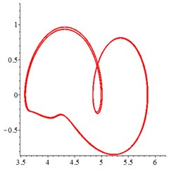
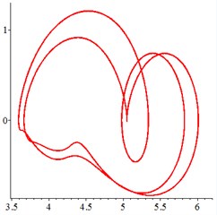
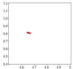
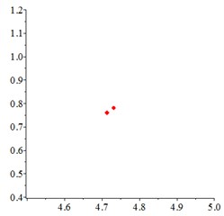
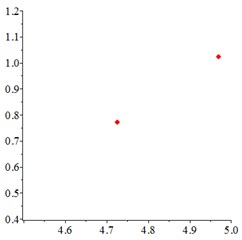
At the medium frequency section ωmesh=[0.5-1.2], in Fig. 7(a), for one observation point on meshing pair Ps1a1, the track of the vibration at different meshing period overlaps as a closed curve. With tooth wear increasing and meshing stiffness decreasing, in Fig. 7(b-c), vibration track area increases, resulting a larger vibration displacement and velocity. In order to confirm the cycle-index of the closed curve Fig. 7(a-c), at the Poincare interface Fig. 7(d), many points gather together at non tooth-condition. With tooth wear increasing in Fig. 7(e-f), Two discrete points occurs, which indicates that the meshing stiffness reduction caused by tooth wear accumulation improves the periodic motion from quasi-period to doubling–period, at the medium frequency section.
Fig. 7At meshing frequency ωmesh= 0.7, the phase trajectory (a-c) and Poincare interface (d-f), x-coordinate is non-dimensional theoretical penetration depth of meshing pair Ps1a1, y-coordinate is non-dimensional theoretical penetration velocity of meshing pair Ps1a1
a) Non-wear
b)Wears1,max= 0.1 mm
c)Wears1,max= 1 mm
d) Non-wear
e)Wears1,max= 0.1 mm
f)Wears1,max= 1 mm
Fig. 8At meshing frequency ωmesh= 1.9, the phase trajectory (a-c) and Poincare interface (d-f). x-coordinate is non-dimensional theoretical penetration depth of meshing pair Ps1a1, y-coordinate is non-dimensional theoretical penetration velocity of meshing pair Ps1a1
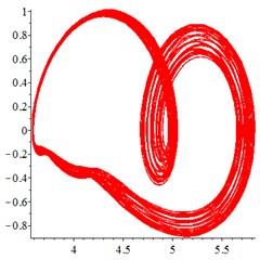
a) Non-wear
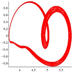
b)Wears1,max= 0.1 mm
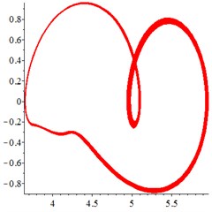
c)Wears1,max= 1 mm
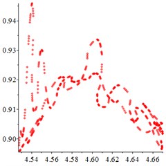
d) Non-wear
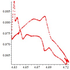
e)Wears1,max= 0.1 mm
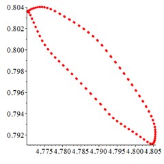
f)Wears1,max= 1 mm
At the high frequency section ωmesh=[1.2-1.9], in Fig. 8(a), for one observation point on meshing pair Ps1a1, the different tracks of the vibration at different meshing period overlaps closed. With tooth wear accumulation and meshing stiffness decreasing in Fig. 8(b-c), the number of closed curves decreases sharply, although chaotic motion occurs. At the Poincare interface Fig. 8(d), the points distributes chaotic. With tooth wear increasing in Fig. 8(e-f), the number of points decreases sharply and distributes more regularly, which indicates that the meshing stiffness reduction caused by tooth wear accumulation improves the periodic motion from chaotic motion to quasi-period, at the high frequency section.
3.2. Load sharing behavior
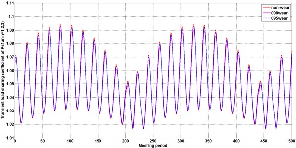
Due to tooth wear increasing on tooth profile, the fluctuation and amplitude of meshing stiffness decreasing causes a smaller fluctuation and a larger amplitude of the vibration on gears in compound planetary gear set, resulting in a different load distribution for the planet gears surround the sun gear [37]. In this chapter, the influence of the meshing stiffness reduced by tooth wear accumulation on the load sharing behavior of compound planetary gear set is investigated by calculating the load sharing coefficient cited in [29], under the condition of different tooth wear depth on tooth profile. In order to reflecting the partial load phenomenon in compound planetary gear set, an eccentricity error is applied on sun gear s1, which is the input gear for the gear transmission.
In order to reveal the influence of the time-varying meshing stiffness decreased by tooth wear accumulation on load distribution behavior at certain time, an transient load sharing coefficient is introduced as the function of time LSCi(t) in Eq. (31), which represents the load distribution behavior at certain discrete times:
To specify the influence of the time-varying meshing stiffness decreased by tooth wear accumulation on load distribution behavior, a set of different maximum amplitudes max(hs1,k,m) of the tooth profile wear on driving gear s1, are introduced into the equations of meshing stiffness in Eqs. (2-22) for the calculation. According to a comparison of Fig. 9(a) and (b), a stronger fluctuation in load sharing coefficient appears at planet-planet meshing pair Panbn, compared with the load sharing coefficient on meshing pair Ps1an. Similarly, with a comparison of Fig. 9(b) and 9(c), a larger load sharing coefficient appears on the meshing pair Ps2bn of output stage. That is indicated that the unbalance loading distribution is magnified with the transfer of power from the input (s1) to the output (s2). With tooth wear increasing, the decreasing amplitude and fluctuation of time-varying stiffness enlarge the load sharing coefficient and improve the load sharing behavior for compound planetary gear set.
3.3. Comparison between the results of this work and other literature
This paper does focus on theoretical analysis and lacks a large number of experimental data to verify the correctness of theoretical results. However, part of the results in chapter 1 and chapter 3 of this paper can be verified by means of literature comparison.
In Fig. 1, the worn tooth profile shape calculated based on 500 discrete points in this work conforms to the worn tooth surface shape obtained by Achard wear theory and single-point observation method. In other words, the wear of tooth tip and tooth root is far greater than that of pitch node, which is verified by [33].
In addition, the influence of tooth wear on meshing stiffness calculated in Fig. 2 shows that, the accumulation of wear on tooth surface reduces the amplitude of meshing stiffness. This result is consistent with the result of reference [31, 32], which can prove the correctness of the calculation method of meshing stiffness under tooth wear condition theoretically derived in this work.
Eqs. (23-28) describe the compound planetary gear kinematics equation derived from Lagrange equation. The equation deriving has been proven in [29, 30, 36]. The innovation of this paper is that the tooth surface wear is introduced into the kinematics equation in the form of numerical excitation, and the change of meshing stiffness and system dynamic characteristics caused by tooth surface wear is calculated and analyzed.
Fig. 9Transient load sharing coefficient of meshing pair Ps1an and Panbn and Ps2bn under different tooth wear condition
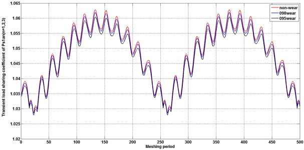
a)Ps1an
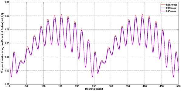
b)Panbn
c)Ps2bn
In Fig. 9, due to the transmission error of the input gear s1 (Table 3 describes the value of the transmission error on input gear s1), partial load distribution occurs in the system, that is, the uniform load coefficient is greater than 1. This is in line with the record in the literature [29, 36] that the transfer error is the fundamental factor that affects the uniform loading.
4. Conclusions
In this work, a numeric model to calculate the time-varying meshing stiffness decreased by tooth wear accumulation on compound planetary gear set is built and incorporated with a “translational-rotational” lumped parameter dynamic model to investigate the influence of the meshing stiffness with tooth profile wear on periodic motion and load sharing behavior of compound planetary gear set. By the analysis of Poincare cross section and phase trajectory, dynamic response in time domain and load sharing behavior for compound planetary gear set is given, it is concluded that:
1) With the accumulation of tooth profile wear, the meshing stiffness of double teeth decreases obviously, and both the stiffness amplitude and fluctuation of single tooth meshing region basically remains unchanged, leading to a decrease in the mean value of time-varying meshing stiffness. The mean value of time-varying meshing stiffness decreases gradually with the accumulation of tooth contact fatigue wear, as well as the fluctuation.
2) The low-frequency motion ωmesh=[0-0.4], the characteristics of compound planetary gear set is stable after introducing the impact of tooth accumulated wear on time-varying meshing stiffness. With the tooth profile wear increasing, the fluctuation coefficient of meshing stiffness decreasing cause a lower fluctuation of vibration and more regular vibration in period at medium frequency section ωmesh=[0.8-0.1.2]. The introduction of tooth wear narrows the Chaos motions section, as well as the scope of vibration amplitude at high frequency section ωmesh= [1.3-2].
3) The meshing stiffness reduction caused by tooth wear accumulation improves the periodic motion from quasi-period to doubling –period, at the medium frequency section, and the meshing stiffness reduction caused by tooth wear accumulation improves the periodic motion from chaotic motion to quasi-period, at the high frequency section.
4) In order to avoid the system being in Chaos motions, under the condition of large tooth wear, the dimensionless meshing frequency ωmesh should be avoided [1.3-2], and the input speed of sun gear s1 is converted into the range of 3700 r/min-6725 r/min, so as to keep the system in a stable periodic motion state as far as possible and reduce the noise.
5) Unbalance loading distribution is magnified with the transfer of power from the input to the output. With tooth wear accumulation, the decreasing amplitude and fluctuation of time-varying stiffness enlarge the load sharing coefficient and improve the load sharing behavior for compound planetary gear set.
Purpose of this work is to make a supplement for the research on influence of tooth wear accumulation on dynamic behavior of gear system, based on the work [28-30, 36]. The calculation model which is used to calculate the decreasing meshing stiffness with tooth profile wear is also appropriate for other gear system, such as parallel-axes gears, simple planetary gear set.
References
-
M. B. Sánchez, M. Pleguezuelos, and J. I. Pedrero, “Approximate equations for the meshing stiffness and the load sharing ratio of spur gears including hertzian effects,” Mechanism and Machine Theory, Vol. 109, pp. 231–249, Mar. 2017, https://doi.org/10.1016/j.mechmachtheory.2016.11.014
-
Y. Sun, H. Ma, Y. Huangfu, K. Chen, L. Che, and B. Wen, “A revised time-varying mesh stiffness model of spur gear pairs with tooth modifications,” Mechanism and Machine Theory, Vol. 129, pp. 261–278, Nov. 2018, https://doi.org/10.1016/j.mechmachtheory.2018.08.003
-
H. Ma, J. Zeng, R. Feng, X. Pang, and B. Wen, “An improved analytical method for mesh stiffness calculation of spur gears with tip relief,” Mechanism and Machine Theory, Vol. 98, pp. 64–80, Apr. 2016, https://doi.org/10.1016/j.mechmachtheory.2015.11.017
-
A. Saxena, A. Parey, and M. Chouksey, “Time varying mesh stiffness calculation of spur gear pair considering sliding friction and spalling defects,” Engineering Failure Analysis, Vol. 70, pp. 200–211, Dec. 2016, https://doi.org/10.1016/j.engfailanal.2016.09.003
-
L. Cui et al., “Method for simulation analysis on meshing stiffness of cylindrical spur gear undergoing damaged single-tooth failure,” Patent 2011102976537, China, 2011.
-
L. Cui, H. Zhai, and F. Zhang, “Cracked gear-tooth meshing stiffness calculation method,” Patent 2015105308136, China, 2015.
-
F. Chaari, T. Fakhfakh, and M. Haddar, “Analytical modelling of spur gear tooth crack and influence on Gearmesh stiffness,” European Journal of Mechanics – A/Solids, Vol. 28, No. 3, pp. 461–468, May 2009, https://doi.org/10.1016/j.euromechsol.2008.07.007
-
Z. Chen, W. Zhai, Y. Shao, K. Wang, and G. Sun, “Analytical model for mesh stiffness calculation of spur gear pair with non-uniformly distributed tooth root crack,” Engineering Failure Analysis, Vol. 66, pp. 502–514, Aug. 2016, https://doi.org/10.1016/j.engfailanal.2016.05.006
-
Z. Chen and Y. Shao, “Mesh stiffness calculation of a spur gear pair with tooth profile modification and tooth root crack,” Mechanism and Machine Theory, Vol. 62, pp. 63–74, Apr. 2013, https://doi.org/10.1016/j.mechmachtheory.2012.10.012
-
Y. Huangfu, K. Chen, H. Ma, L. Che, Z. Li, and B. Wen, “Deformation and meshing stiffness analysis of cracked helical gear pairs,” Engineering Failure Analysis, Vol. 95, pp. 30–46, Jan. 2019, https://doi.org/10.1016/j.engfailanal.2018.08.028
-
L. Chang, G. Liu, and L. Wu, “A robust model for determining the mesh stiffness of cylindrical gears,” Mechanism and Machine Theory, Vol. 87, pp. 93–114, May 2015, https://doi.org/10.1016/j.mechmachtheory.2014.11.019
-
Y. Chen, D. Joffre, and P. Avitabile, “Underwater dynamic response at limited points expanded to full-field strain response,” Journal of Vibration and Acoustics, Vol. 140, No. 5, p. 05101, Oct. 2018, https://doi.org/10.1115/1.4039800
-
Y. Chen, A. S. Escalera Mendoza, and D. T. Griffith, “Experimental and numerical study of high-order complex curvature mode shape and mode coupling on a three-bladed wind turbine assembly,” Mechanical Systems and Signal Processing, Vol. 160, No. 3, p. 107873, Nov. 2021, https://doi.org/10.1016/j.ymssp.2021.107873
-
J. Zhan, M. Fard, and R. Jazar, “A quasi-static FEM for estimating gear load capacity,” Measurement, Vol. 75, pp. 40–49, Nov. 2015, https://doi.org/10.1016/j.measurement.2015.07.036
-
X. Gu, P. Velex, P. Sainsot, and J. Bruyère, “Analytical investigations on the mesh stiffness function of solid narrow faced spur and helical gears,” in ASME 2015 International Design Engineering Technical Conferences and Computers and Information in Engineering Conference, Aug. 2015, https://doi.org/10.1115/detc2015-46061
-
Y. Chen, B. Zhang, N. Zhang, and M. Zheng, “A condensation method for the dynamic analysis of vertical vehicle-track interaction considering vehicle flexibility,” Journal of Vibration and Acoustics, Vol. 137, No. 4, p. 04101, Aug. 2015, https://doi.org/10.1115/1.4029947
-
Y. Chen, B. Zhang, and S. Chen, “Model reduction technique tailored to the dynamic analysis of a beam structure under a moving load,” Shock and Vibration, Vol. 2014, pp. 1–13, 2014, https://doi.org/10.1155/2014/406093
-
M. Zeng, B. Tan, F. Ding, B. Zhang, H. Zhou, and Y. Chen, “An experimental investigation of resonance sources and vibration transmission for a pure electric bus,” Proceedings of the Institution of Mechanical Engineers, Part D: Journal of Automobile Engineering, Vol. 234, No. 4, pp. 950–962, Mar. 2020, https://doi.org/10.1177/0954407019879258
-
D. Wang, D. Zhang, X. Mao, Y. Peng, and S. Ge, “Dynamic friction transmission and creep characteristics between hoisting rope and friction lining,” Engineering Failure Analysis, Vol. 57, No. 8, pp. 499–510, Nov. 2015, https://doi.org/10.1016/j.engfailanal.2015.08.010
-
M. G. Saryazdi and M. Durali, “The effect of three-dimensional crack growth on the force distribution and meshing stiffness of a spur gear: Ideal and misaligned contacts,” Proceedings of the Institution of Mechanical Engineers, Part C: Journal of Mechanical Engineering Science, Vol. 223, No. 7, pp. 1633–1644, Jul. 2009, https://doi.org/10.1243/09544062jmes1217
-
M. B. Sánchez, M. Pleguezuelos, and J. I. Pedrero, “Influence of profile modifications on meshing stiffness, load sharing, and transmission error of involute spur gears,” Mechanism and Machine Theory, Vol. 139, pp. 506–525, Sep. 2019, https://doi.org/10.1016/j.mechmachtheory.2019.05.014
-
Y. Huangfu et al., “Investigation on meshing and dynamic characteristics of spur gears with tip relief under wear fault,” (in Chinese), Science China Technological Sciences, Vol. 62, No. 11, pp. 1948–1960, Nov. 2019, https://doi.org/10.1007/s11431-019-9506-5
-
J. Lin and R. G. Parker, “Mesh stiffness variation instabilities in two-stage gear systems,” Journal of Vibration and Acoustics, Vol. 124, No. 1, pp. 68–76, Jan. 2002, https://doi.org/10.1115/1.1424889
-
G. V. Tordion and R. Gauvin, “Dynamic stability of a two-stage gear train under the influence of variable meshing stiffnesses,” Journal of Engineering for Industry, Vol. 99, No. 3, pp. 785–791, Aug. 1977, https://doi.org/10.1115/1.3439314
-
L. Cui, H. Zhai, and F. Zhang, “Research on the meshing stiffness and vibration response of cracked gears based on the universal equation of gear profile,” Mechanism and Machine Theory, Vol. 94, pp. 80–95, Dec. 2015, https://doi.org/10.1016/j.mechmachtheory.2015.07.011
-
L. Cui, J. Huang, H. Zhai, and F. Zhang, “Research on the meshing stiffness and vibration response of fault gears under an angle-changing crack based on the universal equation of gear profile,” Mechanism and Machine Theory, Vol. 105, pp. 554–567, Nov. 2016, https://doi.org/10.1016/j.mechmachtheory.2016.07.022
-
R. Hbaieb, F. Chaari, T. Fakhfakh, and M. Haddar, “Retracted: dynamic stability of a planetary gear train under the influence of variable meshing stiffness,” Proceedings of the Institution of Mechanical Engineers, Part D: Journal of Automobile Engineering, Vol. 220, No. 7, pp. 1711–1725, Jul. 2006, https://doi.org/10.1243/09544070jauto248
-
S. Wu, H. Zhang, X. Wang, Z. Peng, K. Yang, and W. Zhu, “Influence of the backlash generated by tooth accumulated wear on dynamic behavior of compound planetary gear set,” Proceedings of the Institution of Mechanical Engineers, Part C: Journal of Mechanical Engineering Science, Vol. 231, No. 11, pp. 2025–2041, Jun. 2017, https://doi.org/10.1177/0954406215627831
-
H. Zhang and X. Shen, “A dynamic tooth wear prediction model for reflecting “two-sides” coupling relation between tooth wear accumulation and load sharing behavior in compound planetary gear set,” Proceedings of the Institution of Mechanical Engineers, Part C: Journal of Mechanical Engineering Science, Vol. 234, No. 9, pp. 1746–1763, May 2020, https://doi.org/10.1177/0954406219900085
-
A. Kahraman and H. Ding, “A methodology to predict surface wear of planetary gears under dynamic conditions,” Mechanics Based Design of Structures and Machines, Vol. 38, No. 4, pp. 493–515, Oct. 2010, https://doi.org/10.1080/15397734.2010.501312
-
Z. Shen, B. Qiao, L. Yang, W. Luo, and X. Chen, “Evaluating the influence of tooth surface wear on TVMS of planetary gear set,” Mechanism and Machine Theory, Vol. 136, pp. 206–223, Jun. 2019, https://doi.org/10.1016/j.mechmachtheory.2019.03.014
-
X. Cui, Z. He, B. Huang, Y. Chen, Z. Du, and W. Qi, “Study on the effects of wheel-rail friction self-excited vibration and feedback vibration of corrugated irregularity on rail corrugation,” Wear, Vol. 477, p. 203854, Jul. 2021, https://doi.org/10.1016/j.wear.2021.203854
-
A. Flodin and S. Andersson, “Simulation of mild wear in spur gears,” Wear, Vol. 207, No. 1-2, pp. 16–23, Jun. 1997, https://doi.org/10.1016/s0043-1648(96)07467-4
-
A. Fernandez Del Rincon, F. Viadero, M. Iglesias, P. García, A. De-Juan, and R. Sancibrian, “A model for the study of meshing stiffness in spur gear transmissions,” Mechanism and Machine Theory, Vol. 61, pp. 30–58, Mar. 2013, https://doi.org/10.1016/j.mechmachtheory.2012.10.008
-
W. Chen, M. Jin, J. Huang, Y. Chen, and H. Song, “A method to distinguish harmonic frequencies and remove the harmonic effect in operational modal analysis of rotating structures,” Mechanical Systems and Signal Processing, Vol. 161, p. 107928, Dec. 2021, https://doi.org/10.1016/j.ymssp.2021.107928
-
H. Zhang, S. Wu, and Z. Peng, “A nonlinear dynamic model for analysis of the combined influences of nonlinear internal excitations on the load sharing behavior of a compound planetary gear set,” Proceedings of the Institution of Mechanical Engineers, Part C: Journal of Mechanical Engineering Science, Vol. 230, No. 7-8, pp. 1048–1068, Apr. 2016, https://doi.org/10.1177/0954406215597958
-
J. Liu, B. Qiao, Y. Chen, Y. Zhu, W. He, and X. Chen, “Impact force reconstruction and localization using nonconvex overlapping group sparsity,” Mechanical Systems and Signal Processing, Vol. 162, p. 107983, Jan. 2022, https://doi.org/10.1016/j.ymssp.2021.107983
About this article
The authors would like to thank the Science and technology research project of Hubei Provincial Department of Education of China for the financial and technological support given to this study through the project “Research on Vibration Mechanism of High Speed Gearbox under Internal and External Excitation” Project no B2020142.
The authors would like to thank Xiangyang Science and Technology Research and Development Programme of China for the financial and technological support given to this study through the project “High Speed Gear Box Lubrication and Lightweight Technology” (2020ABH001912).
The authors would like to thank Hubei Superior and Distinctive Discipline Group of “Mechatronics and Automobiles” (XKQ2021043) for the financial and technological support given to this study through the project “Research on Vibration and Noise Reduction Mechanism of High Speed Gear”.

