Abstract
Meshing stiffness is an important factor in gear dynamics analysis. At present, there are many ways to calculate the meshing stiffness of gears, and we usually use the potential energy method to solve and calculate the meshing stiffness of healthy (faulty) gears. In this paper, the potential energy method, the improved potential energy method and the theoretical calculation method are used to solve the time-varying stiffness of the healthy spur gear pair, and the solution results are compared, which verifies the feasibility of the improved potential energy method to solve the gear meshing stiffness.
1. Introduction
Meshing stiffness is an important influencing factor in gear strength design and dynamic analysis, due to the special properties of gear pair structure, the meshing stiffness of gear produces time-varying during the meshing process, and there are many influencing factors. The gear pair will produce periodic changes in the process of meshing, which affects the vibration and noise of the gear system, so the study of the time-varying and periodic nature of the meshing stiffness can better solve the problem of vibration and noise for mechanical transmission [1]. In 1985, Yang et al. used the potential energy method to divide the energy stored in the gear into bending potential energy, axial compression potential energy and Hertzian contact energy, and used it to calculate the corresponding bending stiffness, compressive stiffness and Hertzian stiffness of the gear pair [2]. In 2004, Tian further improved the basic model of meshing stiffness based on Yang, taking into account the influence of shear stiffness on the comprehensive stiffness of gears when establishing the model, making the calculation results more accurate [3]. In 2017, Han et al. studied an improved calculation method for the mesh stiffness of helical gears with frictional effects using the potential energy method, further revealing the dynamic characteristics of helical gears [4]. In 2019, Xiong et al. established an accurate contour equation based on the principle of generative machining and proposed an improved potential energy method for grid stiffness calculation [5]. Zhang Tao et al. derived an analytical formula for the mesh stiffness of spur gears with time-varying friction based on the potential energy method, and analyzed the variation law of the mesh stiffness of spur gear pairs under the effects of no friction, constant friction, and time-varying friction [6]. In the same year, Li Dalei et al. proposed a method for calculating gear mesh stiffness based on the principle of potential energy, and further studied the influence of typical assembly error forms on gear mesh stiffness [7]. In 2020, Wang Xiaopeng et al. proposed an accurate modeling method for time-varying meshing stiffness of spur gear pairs based on geometry and potential energy method, based on the meshing motion equation and geometric position relationship of involute gears [8]. In 2021, Wen et al. proposed a new solution method based on potential energy theory to solve the time-varying mesh stiffness of three-dimensional gear models [9]. In 2022, Cao Dongjiang et al. derived and used the Weber energy method to calculate the deformation of modified gears, providing important support for further research on the dynamics of modified gears [10]. In 2023, Hao Zhuangzhuang et al. established a gear meshing stiffness calculation model based on the energy method, which includes nonlinear Hertz contact stiffness, real tooth profile profile, and matrix stiffness coupling effects. They analyzed the effects of tooth surface friction and geometric eccentricity on the time-varying meshing stiffness of gears [11]. In the same year, Xu Kejun et al. used the potential energy method as a basis to divide the full tooth profile of gears into involute and transitional curve parts, and proposed an improved method for calculating the time-varying mesh stiffness of spur gears [12]. C. Pany used a reference method in 2002 to evaluate the fundamental frequency of a uniform cantilever beam with a large amplitude. And the accuracy of the results was verified. Then, the large deflection data of prismatic and non-prismatic cantilever beams for different taper ratios using the finite element method when subjected to concentrated tip loads are presented. Using the large displacement data that has already been analyzed, a very simple method is used to evaluate the high amplitude first mode frequency of a cantilever beam [13-15]. In this paper, the time-varying meshing stiffness of a spur gear with low number of teeth and large modulus is solved, and the stiffness value generated during the operation of the gear is further solved by using the potential energy method by treating the studied gear teeth as a variable cross-section cantilever beam, and the potential energy method is improved to obtain the improved stiffness value, and the theoretical value is obtained by using the theoretical solution method to compare with it.
2. The traditional potential energy method solves the time-varying meshing stiffness of spur gears
2.1. The basic principle of the potential energy method calculation
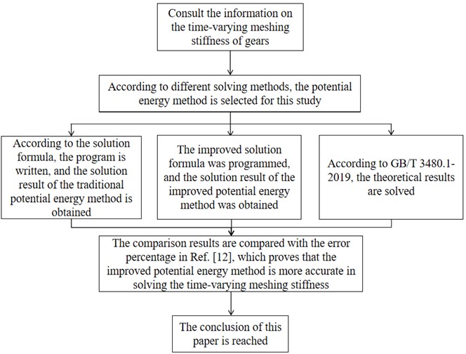
The potential energy method is a method for calculating the meshing stiffness of gears based on the mechanics of materials. In general, the basic idea of calculating gear meshing stiffness is to calculate the actual tooth contact deformation at the discrete rolling position, and thus determine the potential energy accumulated when the gear is meshed. The idea of the potential energy method applied in this paper is to treat the studied gear teeth as a variable cross-section cantilever beam. The flow chart of this article is shown in Fig. 1. During operation, gear teeth will be deformed due to the action of meshing force, such as contact deformation, bending deformation, shear deformation and compression deformation. The occurrence of these deformations causes it to generate potential energies such as contact and bending, which correspond to stiffness such as contact and bending, respectively. Solve for the corresponding stiffness values separately.
Fig. 1Flow chart of the ideas of this article
The total potential energy generated by two meshing gears consists of contact potential energy, bending potential energy, compression potential energy, shear potential energy, and matrix potential energy. Hence the total potential energy can be expressed as:
where, is the meshing stiffness of the gear mesh, is the contact potential energy generated by the contact of the two gears, is the bending potential energy generated by the bending deformation of the gear during the meshing process, is the compression potential energy generated by the compression deformation of the gear during the meshing process, is the shear potential energy generated by the shear force during the gear meshing, and the lower corner marks 1 and 2 are respectively represented as the main and driven gears. Which can be expressed as:
where, , , , respectively represent Hertz stiffness, bending stiffness, axial compression stiffness, and shear stiffness, and their expressions are as follows. The subscripts 1 and 2 represent the driving gear and driven gear in the gear pair:
Eq. (7)-Eq. (10) all are cited from the literature [12]. In the formula, represents the interaction force at the meshing point of the gear teeth, which is decomposed into radial force and tangential force . is the shear modulus, is the moment of inertia of the tooth section at a distance of from the base circle, is the cross-sectional area, is the distance between the meshing point and the base circle, and is the distance between the meshing point and the tooth symmetry line. is the Young’s modulus, represents the Poisson’s ratio, and is the tooth width.
2.2. The gear tooth comprehensive meshing is just solved
Most of the involute spur gear coincidence in our study is between 1-2, and the spur gear meshing process at this time will have the situation of alternating meshing of single and double teeth. As shown in Fig. 2, the teeth that enter the meshing on the left side of the two gears are regarded as the first pair of meshing teeth, and the pair of teeth that gradually exit the meshing on the right are regarded as the second pair of teeth. This pair of gears is assumed to enter the engagement from point A and end the engagement at point P, then the single-tooth region is the BC segment, and the double-tooth region is the AB and CD segments.
According to the single tooth meshing stiffness Eq. (5) above, the comprehensive meshing stiffness formula can be obtained as follows:
where, , , , represent the compressive stiffness, bending stiffness, shear stiffness, and matrix stiffness of the two meshing teeth of the driving wheel. 1, 2 represents the teeth that enter meshing and the teeth that end meshing, respectively.
The above content is the basis for solving the meshing stiffness of gears using the potential energy method. Below, the meshing stiffness of a certain spur gear pair will be solved. The parameters of the spur gear pair are detailed in Table 1. Since the research object of this paper is a wind turbine gear, the following parameters are selected for research and analysis.
Fig. 2Schematic diagram of gear meshing
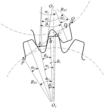
Table 1Spur gear parameters
Parameter name | Parameter symbol | Value |
Number of teeth | , | 20,20 |
Pressure angle | 20 | |
Tooth width | 30 | |
Modulus | 10 | |
Elastic modulus | 2.06×10¹¹ | |
Poisson's ratio | 0.3 |
Substitute the gear pair parameters in Table 1 into the computer software program to calculate the gear mesh stiffness at this time. The calculation result is shown in Fig. 3.
Fig. 3The potential energy method solves the meshing stiffness result diagram
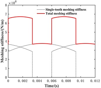
Fig. 3 shows the time-varying mesh stiffness results of the gear pair within two meshing cycles. As shown in the figure, the total time-varying meshing stiffness will experience a sudden decrease at a certain moment within the meshing cycle. At this time, the gear pair is in a transition from a double tooth meshing area to a single tooth meshing area. When a sudden increase occurs, the gear pair is in a transition from a single tooth meshing area to a double tooth meshing area. When in the double tooth meshing zone, the trend of mesh stiffness variation is relatively stable. The total meshing stiffness exhibits periodic variation.
2.3. The improved potential energy method solves the time-varying meshing stiffness of spur gears
According to the geometric characteristics of the involute, the potential energy method simplifies the gear teeth into a cantilever beam on the gear base circle when solving the gear meshing stiffness, but the gear base circle and the tooth root circle do not coincide, which will lead to a certain error when the meshing stiffness is solved, so it is necessary to make appropriate corrections to the potential energy method to reduce the calculation error. The formula for calculating the base radius and root radius of a gear is as follows:
When the tooth top height coefficient and the top clearance coefficient are taken as 1 and 0.25 respectively, it can be obtained that when the number of teeth is 42, the radius of the root circle and the radius of the base circle are about the same. When the number of teeth is less than 42, the radius of the tooth root circle is less than the radius of the base circle, when the potential energy method in the upper section is used to solve the meshing stiffness, the gear teeth are simplified to the cantilever beam on the base circle, which is equivalent to reducing the length of the cantilever beam, and the deformation energy of the gear tooth part between the base circle and the tooth root circle is not calculated, because the deformation energy is inversely proportional to the stiffness, which will lead to the obtained gear tooth stiffness being larger.
In the same way, when the number of gear teeth is greater than 42, the radius of the tooth root circle is greater than the radius of the base circle, and when the potential energy method in the upper section is used to solve the meshing stiffness, the gear teeth are simplified to the cantilever beam on the base circle, which is equivalent to increasing the length of the cantilever beam, and the deformation energy of the gear tooth part between the base circle and the tooth root circle is calculated, so this will lead to the obtained tooth stiffness being small. Therefore, we need to modify the formula for solving the meshing stiffness of the original potential energy method to make the calculation results more accurate.
This article studies the number of teeth in a spur gear, which is 20. Therefore, we need to consider increasing the tooth deformation energy between the base circle and the root circle to achieve balance. Therefore, we can modify the bending stiffness Eq. (3) to:
Similarly, we can derive the modified axial compression stiffness and shear stiffness formulas as follows:
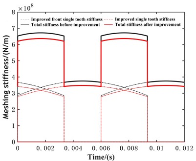
Using computer software to modify the parameters in Table 1, the meshing stiffness of the spur gear pair was obtained using the improved potential energy method. Compare the results before and after improvement, as shown in Fig. 4.
Fig. 4Comparison of time-varying meshing stiffness before and after improvement
2.4. The theoretical method is to solve the meshing stiffness of the gear pair
The theoretical method for solving meshing stiffness is usually based on GB/T 3480.1-2019. In the standard, the formula for calculating the single tooth meshing stiffness per unit tooth width is:
where, is the theoretical value of the stiffness of a single pair of teeth, and ( is the flexibility coefficient); is the theoretical correction coefficient, with a value of 0.8; is the gear blank coefficient, with a value of 1; is the tooth profile coefficient, with a value of 1; is the helix angle.
The formula for calculating the flexibility coefficient is:
where and are the equivalent number of teeth of the driving wheel and the driven wheel respectively; and are the displacement coefficients of the driving wheel and the driven wheel, respectively. The formula for calculating the average meshing stiffness per unit tooth width is:
The calculation formulas for the maximum meshing stiffness , minimum meshing stiffness , and average meshing stiffness of the full tooth width are as follows:
From the above formula, it can be seen that the national standard method can only calculate the constant meshing stiffness of the gear pair when solving the meshing stiffness of the gear pair, and cannot solve the time-varying meshing stiffness. Therefore, this method is now commonly used to verify the calculation results of other methods. The formulas in this section are all quoted from GB/T 3480.1-2019.
In this article, theoretical methods are used to calculate the parameters of the gear pair in Table 1 and Table 2, and the calculation results are shown in Fig. 5.
Fig. 5The theoretical method solves the meshing stiffness result diagram
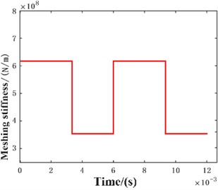
Compare and analyze the meshing stiffness results obtained from the above three methods, as shown in Table 2.
Based on the comparison results in Table 2, we can see that the comprehensive meshing stiffness values calculated by the traditional potential energy method and the improved potential energy method are both within 10 % of the theoretical calculation values. However, the improved potential energy method has a smaller error, which verifies the feasibility and accuracy of the improved potential energy method in solving meshing stiffness in this paper. The final error results obtained in this paper are compared with those obtained in Literature [12], which verifies the feasibility of improving the potential energy method in this paper.
Table 2Comparison of comprehensive meshing stiffness results
Method | Max / ×108 (N/m) | Error (%) | Min / ×108 (N/m) | Error (%) | Average / ×108 (N/m) | Error (%) |
Traditional | 6.718 | 8.565 | 3.672 | 4.022 | 5.356 | 8.224 |
Improved | 6.369 | 2.925 | 3.419 | 3.144 | 5.048 | 2.000 |
Theoretical | 6.188 | 0 | 3.530 | 0 | 4.949 | 0 |
3. Conclusions
This paper mainly focuses on the study of solving the meshing stiffness of gear pairs. The principle and formula of using the potential energy method to solve the meshing stiffness are introduced, and the parameters of a low number of teeth and large modulus spur gear pair are given, and the traditional potential energy method is used to solve the problem, and finally the result diagram of the time-varying meshing stiffness is obtained. Based on the geometric characteristics of the involute, the traditional potential energy method is improved, and the parameters of the same gear pair are used instead of the solution, so as to improve the potential energy method for solving the time-varying mesh stiffness. Compared with the finite element method used in Ref. 7, this paper uses the standard theory algorithm to solve the meshing stiffness of the spur gear pair. By comparing the results obtained by the traditional potential energy method and the improved potential energy method, the error between the improved potential energy method and the theoretical value is controlled within 5 %. The feasibility of solving and analyzing the meshing stiffness of gear pairs by the improved potential energy method proposed in this paper is verified. It laid the foundation for the study of gear dynamics. We can use the improved potential energy method to solve and analyze the meshing stiffness of gears under different parameters (not limited to the number of teeth) to further verify the feasibility of this method.
References
-
S. Wang, “Calculation of meshing stiffness of faulty gears and analysis of system dynamics characteristics,” (in Chinese), Xi'an Ligong University, 2014.
-
D. C. H. Yang and J. Y. Lin, “Hertzian damping, tooth friction and bending elasticity in gear impact dynamics,” Journal of Mechanisms, Transmissions, and Automation in Design, Vol. 109, No. 2, pp. 189–196, Jun. 1987, https://doi.org/10.1115/1.3267437
-
X. H. Tian, “Dynamic simulation for system response of gearbox including localized gear faults,” University of Alberta Library, Jan. 2004.
-
L. Han, L. Xu, and H. Qi, “Influences of friction and mesh misalignment on time-varying mesh stiffness of helical gears,” Journal of Mechanical Science and Technology, Vol. 31, No. 7, pp. 3121–3130, Aug. 2017, https://doi.org/10.1007/s12206-017-0602-6
-
Y. Xiong, K. Huang, F. Xu, Y. Yi, M. Sang, and H. Zhai, “Research on the influence of backlash on mesh stiffness and the nonlinear dynamics of spur gears,” Applied Sciences, Vol. 9, No. 5, p. 1029, Mar. 2019, https://doi.org/10.3390/app9051029
-
T. Zhang, Z. Y. He, S. R. Yin, and S. Z. Sun, “Calculation of meshing stiffness of spur gear pairs considering time-varying friction and analysis of influencing factors,” (in Chinese), Mechanical Transmission, Vol. 43, No. 9, pp. 54–59, 2019, https://doi.org/10.16578/j.issn.1004.2539.2019.09.009
-
D. L. Li, A. M. Li, and E. L. Zhang, “A universal calculation method for time-varying meshing stiffness of gears,” (in Chinese), Journal of Chongqing University of Technology (Natural Science), Vol. 33, No. 10, pp. 61–66, 2019, https://doi.org/10.3969/j.issn.1674-8425(z)
-
X. P. Wang, S. J. Liu, and J. Q. Li, “Accurate modeling and application of time-varying meshing stiffness of spur gear pairs based on geometry and potential energy method,” (in Chinese), Mechanical Transmission, Vol. 44, No. 3, pp. 91–96, 2020, https://doi.org/10.16578/j.issn.1004.2539.2020.03.015a
-
Q. Wen, Q. Chen, Q. Du, and Y. Yang, “Time-varying mesh stiffness calculation for gear pairs with misalignment errors in multiple degrees of freedom based on an analytical method,” Proceedings of the Institution of Mechanical Engineers, Part C: Journal of Mechanical Engineering Science, Vol. 236, No. 1, pp. 689–705, Oct. 2021, https://doi.org/10.1177/09544062211039249
-
D. J. Cao, P. Shang, and Y. Zhao, “Calculation and analysis of time-varying mesh stiffness of involute modified spur gears based on Matlab,” (in Chinese), Mechanical Transmission, Vol. 46, No. 5, pp. 100–107, 2022, https://doi.org/10.16578/j.issn.1004.2539.2022.05.014
-
Z. Z. Hao, Q. C. Zhang, Y. B. Hu, Y. B. Guo, D. H. Wang, and W. Y. Li, “Research on the influence of tooth surface friction and geometric eccentricity on the mesh stiffness of spur gears with variations,” (in Chinese), Chinese Mechanical Engineering, Vol. 34, No. 23, pp. 2812–2823, 2023.
-
K. J. Xu, W. Jiao, and H. L. Qin, “Research on the calculation method of time-varying mesh stiffness of spur gears based on improved potential energy method,” (in Chinese), Mechanical Transmission, Vol. 47, No. 2, pp. 1–7, 2023, https://doi.org/10.16578/j.issn.1004.2539.2023.02.001
-
C. Pany and G. V. Rao, “Calculation of non-linear fundamental frequency of a cantilever beam using non-linear stiffness,” Journal of Sound and Vibration, Vol. 256, No. 4, pp. 787–790, Sep. 2002, https://doi.org/10.1006/jsvi.2001.4224
-
C. Pany and G. V. Rao, “Large amplitude free vibrations of a uniform spring-hinged beam,” Journal of Sound and Vibration, Vol. 271, No. 3-5, pp. 1163–1169, Apr. 2004, https://doi.org/10.1016/s0022-460x(03)00572-8
-
C. Pany, “Large amplitude free vibrations analysis of prismatic and non-prismatic different tapered cantilever beams,” Pamukkale University Journal of Engineering Sciences, Vol. 29, No. 4, pp. 370–376, Jan. 2023, https://doi.org/10.5505/pajes.2022.02489
About this article
This research was funded by basic scientific research projects of Liaoning Provincial Department of Education (JYTMS20230216), the construction plan of scientific research and innovation team of Shenyang Ligong University (SYLU202101).
The datasets generated during and/or analyzed during the current study are available from the corresponding author on reasonable request.
Hao Zhang: data curation, software, original draft preparation and editing. Hongyuan Zhang: manuscript review, put forward comments, and provide methodological ideas.
The authors declare that they have no conflict of interest.
