Abstract
To improve wind turbines’ reliability and lifespan, taking the two-stage fixed shaft gearbox of wind turbines as study object. The oil stiffness and meshing stiffness of the transmission system are calculated, and the composite stiffness is obtained with the consideration of lubricating film. Then analyzed the dynamic characteristics of wind turbines’ transmission system before and after consider the oil stiffness in different operating conditions. The findings indicate that after considering the gear lubrication effect, the composite stiffness gradually decreases as rotational speed increase; within a certain rotational speed range, the tooth-surface load can be reduced, making the system run more smoothly. Therefore, the presence of oil film and its impact on its stiffness cannot be ignored. This study has certain guiding significance in improving the transmission efficiency and reducing noise of wind turbines.
Highlights
- This article calculates the oil stiffness and meshing stiffness of the transmission system. And on this basis, the composite stiffness is obtained with the consideration of lubricating film.
- The dynamic characteristics of wind turbines’ transmission system were analyzed under the different operating considering and not considering the oil stiffness.
- After considering the oil stiffness, the dynamic load of the gear increases significantly, so the presence of oil film and its impact on its stiffness cannot be ignored.
1. Introduction
With the tremendous development of wind energy industry, the requirements of the safety and stability of wind turbines are becoming higher and higher. The gear box is an integral part of the wind turbine, which not only needs safe and stable operation, but also needs to reduce vibration and noise [1]. Most common faults of wind turbines come from gear box, and about 60 % faults of gear box come from gear [2]. The common damage forms of gears include tooth breaking, tooth surface wear, pitting, gluing, etc., among which many damage forms are directly related to lubrication.
A large number of academics have performed investigate the dynamic and lubrication characteristics of wind turbines’ gear box. Xue et al. considered meshing stiffness changing with time excitation of gears, then analyzed the dynamic characteristics and dynamic load distribution law of the gear [3]. Lu et al. obtained the oil film thickness of the meshing area through adopting elastohydrodynamic lubrication theory and carried out numerical analysis on the splashing of lubricating oil in the gearbox [4]. Qin et al. explored the relationship between normal oil film stiffness and curvature radius, suction speed, and load under a critical state [5]. Ankoun et al. concluded in his analysis that the lubrication effect will directly affect the dynamic characteristics of the transmission system [6]. Zhang et al. found as the normal load increases, the stiffness of the oil film also increases [7]. The deficiency lies in neglecting the impact of gear’s surface speed oscillation by impact or vibration, and failing to couple the dynamics oil film for research.
In conclusion, the importance of oil film stiffness has pulled in huge researchers, only lubrication model and dynamic calculated the effects of film. There are few studies involved and neither the modeling nor the calculation of oil film stiffness nor the research on its mechanism are sufficient. In this paper, time-varying oil film stiffness and meshing stiffness of gears were comprehensively considered. And the dynamic lubrication model of transmission system was built to study on the dynamic characteristics considering lubrication effect of gear teeth in different operating conditions.
2. The model of wind turbine’s transmission system
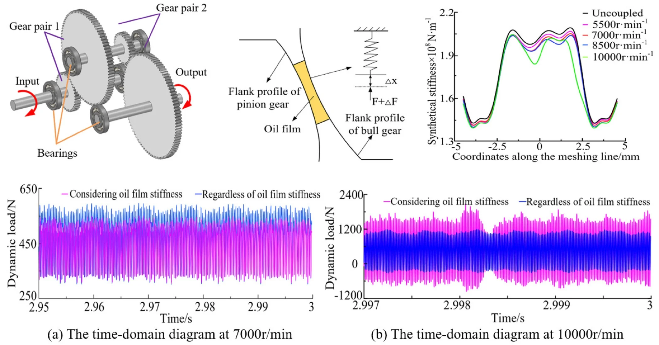
The wind turbine gearbox of the experimental platform is adopted as study object. The transmission system is composed of two gear pairs, three drive shafts and six deep groove ball bearings. The three-dimensional model of transmission system are shown in Fig. 1. Transmission system’s parameters of components and lubricating oil are shown in Table 1.
Table 1The parameters of transmission system and lubricating oil
Parameters | Value |
Gear teeth number | 36, 90, 29, 100 |
Gear mass | 0.16 kg, 1.3 kg, 0.09 kg, 1.6 kg |
Moment of inertia | 2×10⁻⁴ kg·m2, 30.4×10⁻⁴ kg·m2, 1×10⁻⁴ kg·m2, 87.1×10⁻⁴ kg·m2 |
Mesh angle | 20° |
Fig. 13-D model of transmission system
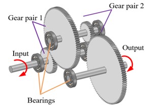
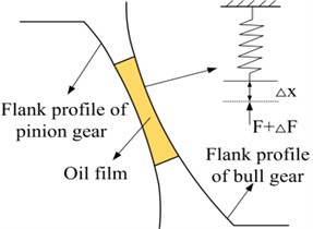
Fig. 2The calculation model of oil film stiffness in the contact area
3. Calculation for stiffness of transmission system
3.1. Calculation method for oil film stiffness
The tooth surfaces that mesh with each other deform not only the contact body, but also the lubricating oil film between the contact bodies, thus forming a stiffness. This paper emphasized the influence of composite stiffness on the dynamic characteristics after the superposition of oil film stiffness and meshing stiffness. Therefore, all oil film stiffness in the following text refers to normal oil film stiffness.
Usually, there are several methods for solving oil film stiffness, such as the global method, the average film thickness method, and the Dowson-Hagginson empirical formula method [8]. This article proposes a theoretical model based on the Dowson-Hagginson empirical formula to gain oil film stiffness. Under a certain speed and load, the oil film will generate viscoelasticity when resisting deformation. In the contact region, the oil film is assumed to be several parallel “small springs” at each node [9], as shown in the Fig. 2.
The normal oil film stiffness’s theoretical calculation formula is:
At the -th node, the calculation formula for the oil film stiffness is:
Replace the corresponding nodes in the contact area with parallel equivalent springs. Therefore, the superposition value of the stiffness of the “small springs” (at each node) in the entire Hertz contact area is the stiffness of the entire contact area. Therefore, the oil film stiffness of the entire contact area in line contact is:
where denotes the width of tooth, is the length of grid without elements, is the Hertz pressure, is the Hertz pressure, b half width of Hertz contact, and are dimensionless oil film pressure and thickness obtained through compute the elastohydrodynamic equation using the Newton-Raphson method [10].
3.2. Calculation method for meshing stiffness
Using the finite element method to sequentially compute the meshing stiffness of all meshing positions within the meshing period. And time-variant meshing stiffness can be obtained with repeat one cycle of gear’s meshing stiffness.
Gear meshing stiffness is the ratio of normal meshing force to deformation, the formula is:
where is the meshing force of tooth surface, is mean deformation, denotes nodes of inner gear ring, pitch radius of driving wheel’s inner gear ring, is pitch radius, is the tiny angle of the driving wheel.
3.3. Calculation method for composite stiffness
When the gear teeth engage, they move from contact to separation and then to contact. In the wedge shaped area, the lubricating oil is involved in and squeezed, forming an oil film with a certain stiffness, which is coupled with the meshing stiffness under dry friction state. The coupled stiffness is the series form of the two stiffness. The coupled stiffness is a series form of the two stiffness. The formula for calculating the composite stiffness of gear is as follows:
where denotes time-varying composite stiffness, is time-varying oil film stiffness, is time-varying meshing stiffness.
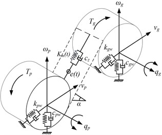
The dynamic model of the gear meshing element established as shown in Fig. 3, the model considers four transverse displacements and two torsional displacements of transmission pair, totaling six degrees of freedom. On this basis, the meshing stiffness is calculated with the finite element method (FEM). In Fig. 3, is the comprehensive error, denotes the pressure angle of the gear pair, , , , , , are translational vibration displacement and torsional angle of the drive and driven wheels respectively. By calculation, it can be inferred that the matrix of composite stiffness is:
Fig. 3The dynamics model of meshing pair
4. Research on dynamic characteristics of transmission system considering lubrication effects
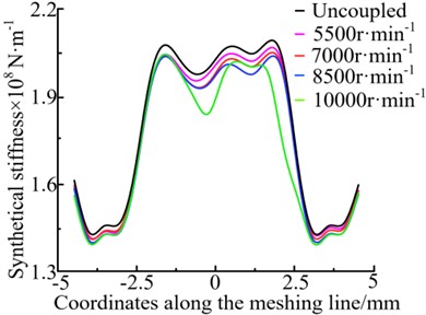
In order to investigate the influence of oil film stiffness on the dynamic characteristics of gear transmission systems, the oil film stiffness and meshing stiffness were superimposed to obtain the distribution of comprehensive stiffness along the meshing line under different working conditions, as shown in Fig. 4. From Fig. 4, it shows that as the rotational speed continues to increase, the overall stiffness shows a decreasing trend. This is because the thickness of the oil film increases with the increase of the speed, resulting in a gradual decrease in the oil film stiffness of the system as the speed increases. Specifically, at 10000 r/min, the comprehensive stiffness undergoes a sudden change, which is because considering the flexibility of the shaft, traditional systems may experience resonance phenomena in certain speed ranges, leading to fluctuations in the dynamic load on the tooth surface, thereby causing changes in the comprehensive stiffness.
Fig. 4Composite stiffness of in different operating conditions
When the load torque is 100 N·m and the speed is 7000 r/min, the dynamic load time domain curve of the gear pair through analysis with and without considering oil film stiffness, as shown in Fig. 5.
From Fig. 5(a), it shows that the amplitude of dynamic load on the tooth surface has significantly decreased after thinking about the oil film stiffness. The maximum dynamic load has decreased from 583.8 N to 541.1 N, with a decrease of 7.44 %. It indicates that considering oil film stiffness can to some extent alleviate the impact and make the transmission smoother.
The meshing frequency of the gear pair can be gained based on the rotational speed, and the calculation formula is:
where denotes the speed of the driving gear, , , are the number of teeth of transmission systems respectively.
Through calculation, it can be concluded that in normal working conditions, the meshing frequency of gear pair 1 is 4200 Hz, and the meshing frequency of gear pair 2 is 1353.3 Hz. From Fig. 5(b), it shows that the main frequency component in the vibration response is the octave component of the meshing frequencies (, ) of the first and second stage gear pairs. After considering the oil film stiffness, the vibration amplitude at the corresponding position of frequency 7+9 decreased from 90.15 N to 80.32 N, and the energy attenuation was 10.9 %.
When the load torque is constant and the speed is 10000 r/min, the dynamic load time-domain curve of the first stage gear pair can be obtained through analysis with and without considering oil film stiffness, as shown in Fig. 6. From Fig. 6 it shows that the maximum dynamic load on the tooth surface of the gear pair is 1206.2 N when the oil film stiffness is not considered. After considering the impact of the oil film stiffness, the load on the tooth surface fluctuates sharply, and the maximum load value increases to 2176.3 N, an increase of 80.43 %. It can also be seen that its meshing frequency is 9+2.The frequency domain amplitude of the uncoupled oil film stiffness is 569.89N, and after coupling the oil film stiffness, it reaches 934.47 N, with an energy increase of 54.14 %. Contrary to the working condition of 7000 r/min, this is due to the high speed, which makes it difficult to form a continuous oil film, resulting in more severe vibration characteristics of the system.
Fig. 5Dynamic load time domain curve of gear pair 1 at 7000 r/min
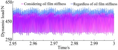
a) The time-domain diagram
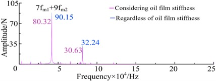
b) The frequency-field diagram
Fig. 6Dynamic load time domain curve of gear pair 1 at 7000 r/min
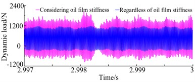
a) The time-domain diagram
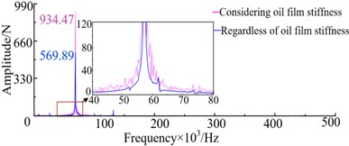
b) The frequency-field diagram
From the above analysis, it can be concluded that considering the oil film stiffness plays a crucial role in the dynamic analysis of the transmission system at different speeds. Therefore, the oil film stiffness cannot be ignored in the analysis.
5. Conclusions
The two-stage cylindrical spur gear reducer of the wind turbine is taken as the research object, and its dynamic characteristics with or without oil film stiffness are analyzed. The main conclusions are as follows:
1) Considering the elastohydrodynamic lubrication effect of lubricating oil, the composite stiffness is obtained by superimposing the oil film stiffness and meshing stiffness.
2) Analyzed the variety rule of the oil film stiffness of the transmission system in different rotational speeds and the variety rule of the composite stiffness when considering lubrication characteristics. It was found that as the rotational speed continues to increase, the oil film stiffness and composite stiffness both continuously decrease.
3) Analyzed the dynamic load changes on the tooth surface of the first stage gear pair under different rotational speeds and whether oil film stiffness is considered. When the rotational speed is 7000 r/min, the dynamic load value and amplitude decreases considering the lubrication effect. When the speed is 10000 r/min, the results are completely opposite. Therefore, the stiffness of the oil film plays a crucial role in the dynamic characteristics of the system and cannot be ignored.
References
-
P. Velex and M. Maatar, “A mathematical model for analyzing the influence of shape deviations and mounting errors on gear dynamic behavior,” Journal of Sound and Vibration, Vol. 191, No. 5, pp. 629–660, Apr. 1996, https://doi.org/10.1006/jsvi.1996.0148
-
H. J. Wang, X. S. Du, and X. Y. Xu, “Dynamic analysis and experimental study of MW wind turbine gearbox,” Applied Mechanics and Materials, Vol. 86, pp. 739–742, Aug. 2011, https://doi.org/10.4028/www.scientific.net/amm.86.739
-
J.-H. Xue, W. Li, and C. Qin, “The scuffing load capacity of involute spur gear systems based on dynamic loads and transient thermal elastohydrodynamic lubrication,” Tribology International, Vol. 79, pp. 74–83, Nov. 2014, https://doi.org/10.1016/j.triboint.2014.05.024
-
F. Lu, K. Wei, M. Wang, M. Li, and H. Bao, “Oil film deposition characteristics and judgment of lubrication effect of splash lubricated gears,” Journal of Mechanical Science and Technology, Vol. 37, No. 5, pp. 2383–2393, May 2023, https://doi.org/10.1007/s12206-023-0415-8
-
W. Qin, J. Chao, and L. Duan, “Study on stiffness of elastohydrodynamic line contact,” Mechanism and Machine Theory, Vol. 86, pp. 36–47, Apr. 2015, https://doi.org/10.1016/j.mechmachtheory.2014.12.001
-
M. Ankouni, A. Lubrecht, and P. Velex, “Modelling of damping in lubricated line contacts – Applications to spur gear dynamic simulations,” Proceedings of the Institution of Mechanical Engineers, Part C: Journal of Mechanical Engineering Science, Vol. 230, No. 7-8, pp. 1222–1232, Jan. 2016, https://doi.org/10.1177/0954406216628898
-
Y. Zhang, H. Liu, C. Zhu, M. Liu, and C. Song, “Oil film stiffness and damping in an elastohydrodynamic lubrication line contact-vibration,” Journal of Mechanical Science and Technology, Vol. 30, No. 7, pp. 3031–3039, Sep. 2016, https://doi.org/10.1007/s12206-016-0611-x
-
Y. Peng, N. Zhao, P. Qiu, M. Zhang, W. Li, and R. Zhou, “An efficient model of load distribution for helical gears with modification and misalignment,” Mechanism and Machine Theory, Vol. 121, pp. 151–168, Mar. 2018, https://doi.org/10.1016/j.mechmachtheory.2017.10.019
-
Y. Zhang, H. Liu, C. Zhu, C. Song, and Z. Li, “Influence of lubrication starvation and surface waviness on the oil film stiffness of elastohydrodynamic lubrication line contact,” Journal of Vibration and Control, Vol. 24, No. 5, pp. 924–936, Aug. 2016, https://doi.org/10.1177/1077546316655024
-
L. H. Chang, G. Liu, L. Y. Wu, and Z. H. Bu, “Research on vibration influence chart of planetary gear systems,” Applied Mechanics and Materials, Vol. 86, pp. 747–751, Aug. 2011, https://doi.org/10.4028/www.scientific.net/amm.86.747
About this article

The paper is supported by funding project with the number of BS190220.
The datasets generated during and/or analyzed during the current study are available from the corresponding author on reasonable request.
The authors declare that they have no conflict of interest.
