Abstract
The object of research is a pneumatic spring of high-speed rolling stock of the railway. The method of experimental static testing of a pneumatic spring of high-speed rolling stock is presented. Based on experimental tests, the “force-strain” dependences of a pneumatic spring are obtained when the pressure gauge in the pneumatic spring changes from 2.5 atm up to 5.0 atm. Using a thermodynamic model, a quadratic equation is found to determine the effective area of a pneumatic spring. It is established that when the pressure gauge in the pneumatic spring changes from 2.5 atm up to 5.0 atm the effective area of the pneumatic spring varies from 0.231 m2 to 0.306 m2. The scientific novelty lies in the fact that for the first time, on the basis of static experiments, the change in the effective area of the pneumatic spring of high-speed rolling stock depending on the value of the gauge pressure in the spring was established. This will make it possible to determine the forces acting on the pneumatic spring in different operating conditions, ensuring the required level of safety of rolling stock.
1. Introduction
The pneumatic spring is the main structural element of the pneumatic spring suspension system for high-speed rolling stock, which is a rubber-cord shell [1], which is filled in working condition with compressed air with a certain working pressure. The geometric parameters of a pneumatic spring are the following: volume, height, and effective area. The effective area is a variable imaginary area that is assumed to be affected by the relative internal pressure of the pneumatic spring. Since this area does not correspond to a geometrically defined value, it is estimated by experimental tests at constant internal pressure, at which the force is determined when the height of the pneumatic spring changes.
During the operation of a rolling stock, the geometric parameters of the pneumatic spring change, which is associated with a change in the applied load and air flow between the pneumatic spring and the additional tank. Changing the parameters will affect the dynamic characteristics of the pneumatic spring and the system as a whole [2], [3]. In the process of designing high-speed rolling stock, it is important to determine reliable dynamic characteristics of bindings between structural elements of rolling stock. This will allow designers, even at the design stage, to study various operating conditions of rolling stock, ensuring an acceptable level of dynamic indicators and traffic safety indicators, as well as to set optimal parameters of the pneumatic spring suspension system in high-speed traffic conditions [4], [5]. So, the establishment of the effective area of the pneumatic spring of high-speed rolling stock, depending on its operating conditions, is an urgent task that will allow determining the safe operating conditions of rolling stock in high-speed traffic even at the design stage.
2. Literature review and problem statement
The use of a pneumatic spring suspension system in the mechanical part of rolling stock reduces the level of dynamic forces when the rolling stock interacts with the rail track and improves the criteria for driving comfort. The influence of geometric parameters of a pneumatic spring on its dynamic characteristics can be studied on the basis of mechanical, thermodynamic, and computer models [6]-[8]. In [9], the author modeled and analyzed the air suspension, taking into account its main structural elements. Modeling of air suspension was based on determining its axial (vertical) stiffness:
where is the vertical load; is the amount of vertical deformation; is the air pressure in the pneumatic spring; is the effective area of the pneumatic spring, that is the area for load transfer.
Eq. (1) shows that the stiffness of a pneumatic spring mainly depends on changes in pressure and effective area. However, the paper [9] notes that the influence of changes in the effective area of a pneumatic spring on its dynamic characteristics is insignificant. In the future, the stiffness of the pneumatic spring is determined using the second term in the conditions of polytropic transformation. In [10]-[11], the authors performed vehicle modeling, taking into account both multi-body and pneumatic aspects. However, when determining the stiffness of a pneumatic spring, the nominal value of its effective area did not change during the modeling process.
In [12], the author conducted experimental studies to determine the effective area as a function of pressure and the effective area as a function of the volume of a pneumatic spring during an isothermal test. In [13], the authors performed mathematical modeling of the pneumatic spring suspension system and its impact on the safety and comfort of movement. Two different approaches to modeling the air spring suspension were developed: quasi-static, in which the frequency-dependent behavior of the suspension is ignored, but the relationship between shear stiffness and roll is taken into account, and dynamic, in which the frequency-dependent behavior of the suspension in the vertical direction is presented using a thermodynamic model, and the dependence of the lateral stiffness parameters on the load is additionally included. To compare the obtained experimental data with theoretical ones, the authors used a dynamic model of a pneumatic spring suspension system [14]. However, the accepted model assumes certain assumptions, namely, once the pressure inside the pneumatic spring is known, it is possible to estimate the vertical force of the pneumatic spring, assuming that the effective area of the pneumatic spring does not depend on its internal pressure.
In [15], mathematical models of the operation of a pneumatic spring suspension system were created using structural mechanics, fluid mechanics, and engineering thermodynamics. During the modeling process, the effective area of the pneumatic spring was assumed to be constant.
In [16], an analytical model of a pneumatic spring suspension system was developed on the basis of experimental studies. It was found that the effective area and volume of a pneumatic spring are almost independent of pressure, and importantly, both functions are close to linear.
To model the dynamic behavior of a pneumatic spring of high-speed rolling stock, the authors of [17] derived a three-dimensional mathematical model. It is stipulated that during the operation of the pneumatic spring, its volume and effective area change.
The change in the volume of a pneumatic spring consists of two components: one is associated with a change in the height of the pneumatic spring; the other is due to radial deformation of the spring, which is caused by a change in internal pressure. The change in the effective area occurs as a result of vertical deformation of the pneumatic spring. In [14], the authors present a dimensionless mathematical model that allows us to understand the influence of parameters that determine the pneumatic spring suspension system, and correctly choose the type of pneumatic spring. It is noted that the mathematical model should take into account the change in the effective area and volume depending on the internal pressure and vertical deformation of the pneumatic spring. However, according to experimental data, the effect of internal pressure is insignificant. Therefore, as a first approximation, it is assumed that the change in the effective area occurs solely due to changes in the vertical deformation of the pneumatic spring.
Based on the theory of thermomechanics and hydrodynamics in [18], the authors derive a calculation model for determining the dynamic stiffness of a pneumatic spring. The authors note the need to take into account changes in the effective area and volume of the pneumatic spring in the process of determining the dynamic characteristics of the pneumatic spring suspension system.
So, after analyzing the research works [6]-[18], it should be emphasized that currently a significant number of studies have been performed that are related to determining the dynamic characteristics of a pneumatic spring suspension system. However, in most studies, changes in the geometric parameters of a pneumatic spring are ignored, since the determination of such a change is associated with experimental studies. Thus, the first step in studying the dynamic characteristics of a pneumatic spring suspension system is to establish the effective area of the pneumatic spring, which will contribute to the correct determination of dynamic indicators and safety indicators of rolling stock in high-speed traffic conditions.
3. Purpose and objectives of the study
The aim of the work is to determine the effective area of the pneumatic spring of high-speed rolling stock when the internal pressure value changes and the vertical deformation of the pneumatic spring. To achieve this goal, the following tasks must be completed: to develop a methodology for experimental studies to determine the effective area of a pneumatic spring depending on the internal pressure and vertical deformation of the pneumatic spring; determine the effective area of the pneumatic spring of high-speed rolling stock and its change depending on the internal pressure and vertical deformation of the pneumatic spring of 33 mm.
4. Methodology for experimental determination of the effective area of a high-speed rolling stock pneumatic spring
The study of the features of changing the effective area of the pneumatic spring of high-speed rolling stock was carried out under laboratory conditions. For this purpose, an experimental installation for testing the spring for static loads has been developed. The unit consists of components of a pneumatic spring suspension system and measuring equipment. A view of the experimental laboratory installation is shown in (Fig. 1). The method of studying the change in the effective area of a pneumatic spring involved measuring vertical and horizontal deformations of the spring depending on the pressure gauge in the spring. During the experiment, the pressure varied from 2.5 atm. up to 5.0 atm. using a high-pressure compressor. When the pressure changes by 0.5 atm. the spring deformation was recorded using Potentiometric linear displacement sensors and an analog-to-digital converter. The measured data was stored on a personal computer. Control of the applied load value (from the hydraulic jack and air injection into the spring) on the pneumatic spring was carried out by a strain gauge force sensor.
5. Results obtained
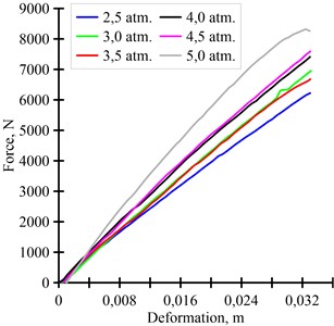
In this paper, the considered pneumatic spring suspension system consists of three main parts: a pneumatic spring, an additional tank and a connecting pipeline. Based on the conducted experimental studies, the “force-strain” dependences of a pneumatic spring were constructed when the manometric pressure changes in the pneumatic spring suspension system (Fig. 2).
The obtained “force-strain” dependences of a pneumatic spring when the pressure gauge changes are necessary for finding the static vertical stiffness of the pneumatic spring. To find the effective area of a pneumatic spring, we apply a thermodynamic mathematical model of the operation of a pneumatic spring. During the operation of the pneumatic spring suspension system, the minimum stiffness of the pneumatic spring is achieved under isothermal compression conditions, and the maximum – under adiabatic compression conditions. The formula for determining the pressure under isothermal compression conditions has the form:
where is the initial absolute pressure; is the final absolute pressure; is the initial volume; is the final volume after compression or expansion.
Fig. 1Laboratory experimental installation for testing pneumatic springs: ADC – analog-to-digital converter, PC – personal computer
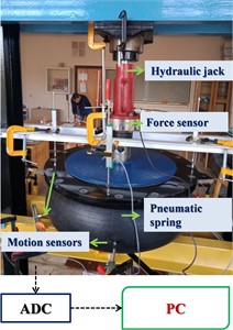
Fig. 2Experimental “force-strain” dependences of a pneumatic spring
However, when operating rolling stock, the working of the pneumatic spring in isothermal conditions is not possible. To preserve the heat generated during the operation of the pneumatic spring, that is if an adiabatic process occurs, Eq. (2) will have the following form:
The value of the degree indicatorvaries depending on the gas and is a function of the specific heat capacity of the gas. To determine the force at any point of the pneumatic spring stroke, the atmospheric pressure must be derived from the absolute pressure values to obtain the pressure gauge. The force (or load) on a pneumatic spring at any point on the “force-strain” curve is the pressure multiplied by the effective area:
where is the gauge pressure; is the effective area of the pneumatic spring.
Differentiating Eq. (3) to find the pressure change, we obtain:
Accepting that , the pressure change equation can be written as follows:
Depending on the rate of deformation of the pneumatic spring, different stiffness constants can be obtained. Dynamic stiffness:
Quasi-static stiffness:
Taking into account the quasi-static conditions of the experiment, we use Eq. (8) to find the effective area of the pneumatic spring.
Therefore, the effective area of a pneumatic spring can be found using the quadratic equation:
After performing mathematical calculations at different values of internal pressure and vertical deformation, ranges of changes in the effective area of the pneumatic spring were obtained, the values of which are summarized in Table 1. The maximum value of vertical deformation of the pneumatic spring was 33 mm. The analysis shows that the change in the effective area of a pneumatic spring in percentage terms ranges from 9.7 % to 12.8 %. The maximum change in the effective area is observed at an internal pressure of 3.0 atm. the range of changes of which is from 0.250 m2 to 0.282 m2. It is established that with an increase in the internal pressure in a pneumatic spring, the value of its effective area decreases, which is explained by the peculiarities of changing the vertical stiffness of the pneumatic spring.
Table 1Range of changes in the effective area of the pneumatic spring
Internal pressure value, atm | Range of changes in the effective area of the pneumatic spring, m2 |
2.5 | 0.279…0.306 |
3.0 | 0.250…0.282 |
3.5 | 0.245…0.269 |
4.0 | 0.241…0.266 |
4.5 | 0.233…0.261 |
5.0 | 0.231…0.257 |
In the future, this will allow designers to study the effect of internal pressure and vertical deformation of the pneumatic spring on the value of its effective area even at the design stage. Together, this will help determine the forces acting on the pneumatic spring. At an internal pressure of 2.5 atm vertical deformation of the pneumatic spring varies from 5.7 mm to 32.5 mm, the effective area of the pneumatic spring varies from 0.279 m2 to 0.306 m2. The force that act on the pneumatic spring is in the range from 1210 N to 6160 N. At an internal pressure of 5.0 atm and the effective area from 0.231 m2 to 0.257 m2, the force that acts on the pneumatic spring, varies from 1670 N to 8330 N. In the future, the values of these forces will determine the level of dynamic indicators and safety indicators of rolling stock under various conditions of its operation.
6. Conclusions
1) A methodology for experimental studies of the operation of a pneumatic spring suspension system with an internal pressure change from 2.5 atm up to 5.0 atm and vertical deformation of the pneumatic spring of 33 mm has been developed. On the basis of experimental studies, the “force-strain” relationships of a pneumatic spring are constructed.
2) Using a thermodynamic mathematical model of the operation of a pneumatic spring, a quadratic equation was obtained to find the effective area of a pneumatic spring. It is established that the change in the effective area of a pneumatic spring in percentage terms ranges from 9.7 % to 12.8 %. The maximum change in the effective area of the pneumatic spring occurs at an internal pressure of 3.0 atm and ranges from 0.250 m2 to 0.282 m2. It is shown that the value of the internal pressure and the effective area of the pneumatic spring can determine the forces acting on the pneumatic spring, providing the necessary level of traffic safety.
References
-
Z. Qi, F. Li, and D. Yu, “A three-dimensional coupled dynamics model of the air spring of a high-speed electric multiple unit train,” Proceedings of the Institution of Mechanical Engineers, Part F: Journal of Rail and Rapid Transit, Vol. 231, No. 1, pp. 3–18, Aug. 2016, https://doi.org/10.1177/0954409715620534
-
A. Kuzyshyn et al., “Research of safety indicators of diesel train movement with two-stage spring suspension,” in MATEC Web of Conferences, Vol. 234, p. 05003, Nov. 2018, https://doi.org/10.1051/matecconf/201823405003
-
A. Kuzyshyn, J. Sobolevska, S. Kostritsa, A. Batig, and V. Boiarko, “Mathematical modeling of the second stage of spring suspension of high-speed rolling stock,” in Reliability and Durability of Railway Transport Engineering Structure and Buildings, Vol. 2684, No. 1, p. 02000, Jan. 2023, https://doi.org/10.1063/5.0120402
-
A. Kuzyshyn, V. Kovalchuk, V. Stankevych, and V. Hilevych, “Determining patterns in the influence of the geometrical parameters of the connecting pipeline on the dynamic parameters of the pneumatic spring of railroad rolling stock,” Eastern-European Journal of Enterprise Technologies, Vol. 1, No. 7 (121), pp. 57–65, Feb. 2023, https://doi.org/10.15587/1729-4061.2023.274180
-
A. Kuzyshyn, A. Batig, S. Kostritsa, J. Sobolevska, S. Dovhaniuk, and V. Dzhus, “Study of the dynamic behavior of rolling stock using a computer experiment,” in IOP Conference Series: Materials Science and Engineering, Vol. 985, No. 1, p. 012002, Nov. 2020, https://doi.org/10.1088/1757-899x/985/1/012002
-
M. Presthus, “Derivation of air spring model parameters for train simulation,” Lulea University of Technology, Derby, UK, 2002.
-
B. M. Eickhoff, J. R. Evans, and A. J. Minnis, “A review of modelling methods for railway vehicle suspension components,” Vehicle System Dynamics, Vol. 24, No. 6-7, pp. 469–496, Jul. 1995, https://doi.org/10.1080/00423119508969105
-
M. Berg, “A three-dimensional air spring model with friction and orifice damping,” Vehicle System Dynamics, Vol. 33, No. 1, pp. 528–539, 1999.
-
M. A. Spiroiu, “Railway vehicle pneumatic rubber suspension modelling and analysis,” Materiale Plastice, Vol. 55, No. 1, pp. 24–27, Mar. 2018, https://doi.org/10.37358/mp.18.1.4956
-
N. Docquier, P. Fisette, and H. Jeanmart, “Model-based evaluation of railway pneumatic suspensions,” Vehicle System Dynamics, Vol. 46, No. sup1, pp. 481–493, Sep. 2008, https://doi.org/10.1080/00423110801993110
-
N. Docquier, Fisette, and Jeanmart, “Influence of heat transfer on railway pneumatic suspension dynamics,” in 21th IAVSD Symposium on Dynamics of Vehicles on Roads and Tracks, 2009.
-
N. Docquier, “Multiphysics modelling of multibody systems application to railway pneumatic suspensions,” Ph.D. Thesis, Université catholique de Louvain, Louvain-Ia-Neuve, Belgium, 2010.
-
A. Facchinetti, L. Mazzola, S. Alfi, and S. Bruni, “Mathematical modelling of the secondary airspring suspension in railway vehicles and its effect on safety and ride comfort,” Vehicle System Dynamics, Vol. 48, No. sup1, pp. 429–449, Dec. 2010, https://doi.org/10.1080/00423114.2010.486036
-
G. Quaglia and M. Sorli, “Air suspension dimensionless analysis and design procedure,” Vehicle System Dynamics, Vol. 35, No. 6, pp. 443–475, Jun. 2001, https://doi.org/10.1076/vesd.35.6.443.2040
-
H. X. Gao, M. R. Chi, M. H. Zhu, and P. B. Wu, “Study on different connection types of air spring,” Applied Mechanics and Materials, Vol. 423-426, pp. 2026–2034, Sep. 2013, https://doi.org/10.4028/www.scientific.net/amm.423-426.2026
-
A. J. Nieto, A. L. Morales, A. González, J. M. Chicharro, and P. Pintado, “An analytical model of pneumatic suspensions based on an experimental characterization,” Journal of Sound and Vibration, Vol. 313, No. 1-2, pp. 290–307, Jun. 2008, https://doi.org/10.1016/j.jsv.2007.11.027
-
A. Kuzyshyn, V. Kovalchuk, Y. Sobolevska, Y. Royko, and I. Kravets, “Determining the effect of additional tank volume and air pressure in the spring on the dynamic indicators of a pneumatic system of spring suspension in high-speed railroad rolling stock,” Eastern-European Journal of Enterprise Technologies, Vol. 3, No. 7 (129), pp. 47–62, Jun. 2024, https://doi.org/10.15587/1729-4061.2024.304051
-
Zhu Sihong, Wang Jiasheng, and Zhang Ying, “Research on theoretical calculation model for dynamic stiffness of air spring with auxiliary chamber,” in IEEE Vehicle Power and Propulsion Conference (VPPC), Sep. 2008, https://doi.org/10.1109/vppc.2008.4677717
About this article

The authors have not disclosed any funding.
The datasets generated during and/or analyzed during the current study are available from the corresponding author on reasonable request.
The authors declare that they have no conflict of interest.
